Tamio KAWAGUCHI†a), Noritsugu SHIOKAWA†, Members, Kohei NAKAYAMA†, Takatoshi WATANABE†, Nonmembers, Tatsunori HASHIMOTO†, and Hiroyuki KAYANO†, Members
SUMMARY We have developed a high-temperature superconducting (HTS) filter with narrow bandwidth characteristic for receiver of weather radar in order to reduce interference between adjacent radar channels. To realize a filter with which a narrow bandwidth and low insertion loss are compatible, resonators with high unloaded Q (Qu) value are required. Hair-pin microstrip resonators with 1.5 times wavelength were adopted to sup-press the radiation loss and achieve a high Quvalue. The developed HTS filter has 8-pole quasi-elliptic function response for sharp skirt characteris-tic. The measured frequency response of the developed filter shows center frequency of 5370 MHz, insertion loss of 2.04 dB and maximum return loss of 15 dB, which agrees with the designed responses.
key words: superconducting filter, weather radar, microstrip line 1. Introduction
Various mobile communication systems have been rapidly adopted in recent years for diverse applications. Conse-quently, the need for full and effective use of frequency re-sources is become increasingly acute. The 5250–5850 MHz band is now being used by systems such as those for marine radar and weather radar. Furthermore, as part of efforts to establish a global standard, the 2003 World Radio commu-nication Conference (WRC-03) decided to make additional allotments to wireless access systems, including wireless LAN systems, from a part of this frequency band. There-fore, it is also necessary to consider narrowing the frequency band currently used by weather radar systems and utilizing a higher frequency band for those with a comparatively nar-row observation range in order to use this frequency band effectively.
In this paper, we report on the development of nar-rowband filter technology to reduce the allocated bandwidth of 5 GHz-band weather radar systems, since it is assumed that the 5 GHz band will be expanded for 5 GHz-band wire-less LAN systems in accordance with “Guidelines for radio spectrum reallocation” announced by the Ministry of Inter-nal Affairs and Communications of Japan. Since the surface resistance of a high-temperature superconductor (HTS) is two or more orders of magnitude smaller than that of cop-per even at 5 GHz band, a band-pass filter with a low inser-tion loss and a narrow bandwidth is expected to be realized by using this characteristic [1]–[3]. And miniaturized HTS
Manuscript received July 1, 2008. Manuscript revised September 18, 2008.
†The authors are with Toshiba Corporation, Kawasaki-shi, 212-8582 Japan.
a) E-mail: [email protected] DOI: 10.1587/transele.E92.C.296
band-pass filters for mobile communication systems are de-veloped by using small-sized microstrip spiral resonators on LaAlO3substrate [16], [17].
In this paper, we have developed a narrow bandwidth HTS filter for the receiver of the radar systems, which has the center frequency of 5730 MHz and the bandwidth of 3 MHz.
2. Filter Design
2.1 Specification
The frequency allocation space between 5 GHz-band weather radar channels is 10 MHz at present. In this pa-per, we report on the development of the receiving filter, the specification of which is located at 2.5 MHz between adjacent radar channels for effective use of frequency re-sources. In this case, we suppose the bandwidth of trans-mission signal at each channel is 1.2 MHz. Figure 1 shows a channel model for 5 GHz-band weather radar systems. In Fig. 1, the n-th channel CHn shows desired signal. CHn−1
and CHn+1show adjacent channels, which are interference
spectra. Therefore, it is necessary for the receiving filter to have high-selectivity at center frequency, f0±1.9 MHz, in
order to reduce interference between adjacent channels. Ac-cording to the specification of the receiving filter, the cen-ter frequency is 5370 MHz. The bandwidth of this filcen-ter is 3 MHz and the fractional bandwidth is 0.08%. The insertion loss is less than 2.5 dB at f0. Attenuation at f0±1.9 MHz is
less than−30 dB.
Fig. 1 Channel model for 5 GHz-band weather radar systems.
Fig. 2 Coupling structure of 8-pole quasi-elliptic function filter.
Fig. 3 Calculated transmission response of the 8-pole quasi-elliptic function filter by means of circuit simulation.
2.2 Design of Circuit Structure
In order to realize the sharp-cut filter with the advantage of the high-unloaded Q (Qu) resonator, the 8-pole quasi-elliptic
function structure shown in Fig. 2 was adopted. Num-bered circles indicate the resonators. Solid lines indicate the external-QQeand coupling factor M. The quasi-elliptic
function is realized by coupling between the 1st resonator and the 4th resonator and between the 5th resonator and the 8th resonator [4]. M14and M58couplings for the
quasi-elliptic function filter are added in the design theory of the Chebyshev filter [5]. These couplings produce two trans-mission zeros at both sides of the desired frequency band. Therefore, the quasi-elliptic function filter is able to realize a superior sharp-cut around filter pass-band compared with the Chebyshev filter.
Figure 3 shows a calculated transmission response of the 8-pole quasi-elliptic filter with high Qu resonator of
40000 by means of a circuit simulation. The filter using the newly developed high Quresonator has smaller insertion
loss than the filter using the conventional low Quresonator.
The designed filter has symmetrical coupling structure, the attenuation poles of which are degenerated. The location of attenuation poles is f0±1.9 MHz. The insertion loss at f0is
1.8 dB.
2.3 Design of Resonator
Figure 4 shows an illustration of the loss for microstrip line
Fig. 4 Illustration of the loss for microstrip line resonator.
Fig. 5 Layout of hairpin microstrip line resonator with 1.5 times wavelength.
resonator. The Quof microstrip resonator consists of three
Q factors, Q for dielectric loss (Qd), Q for conductor loss
(Qc), and Q for radiation loss (Qr) [6], [7]. The relationship
of Qu, Qd, Qc, and Qrcan be written as
1 Qu = 1 Qd + 1 Qc+ 1 Qr. (1)
Qc decreases at high frequency, since surface resistance of
a superconductor is proportional to (frequency)2[8], [7]. Q r
decreases by a larger gradient than Qc. Qr is smaller than
Qc and is dominant for Qu in high-frequency region. For
this reason, generally, cavity resonators and strip line res-onators have been used [9]–[12]. These resres-onators do not have radiation loss.
The microstrip line resonator radiates from impedance mismatch points, such as end of the line and corner of the line. Generally, the microstrip line resonator with both ends open has radiation loss. In order to suppress the radiation, two radiation points with opposite phase were juxtaposed. Figure 5 shows the layout of hairpin microstrip line res-onator with 1.5 times wavelength to suppress the radiation [13]. The w and s indicate the line width and line space respectively. The longer resonator length is, the more Qu
increases, because radiation energy is constant but stored energy increases.
Figure 6 shows the calculated result of Qu as a
func-tion ofw and s. The shade of the color indicates Qu value;
black indicates Qu = 30000, white indicates Qu = 40000.
The radiation loss is suppressed by makingw and s small, because it causes the radiation points with opposite phase mutually to be close. On the other hand, the conductor loss is increased by making w and s small, because it causes the current concentration to edge of a microstrip line. For
Qu, the maximum is decided by the trade-off with Qcand
Qr. As a result, s of 0.5 mm andw of 0.5 mm were
deter-mined for a resonator with the maximum Qu. But the
Fig. 6 A calculated result of Quas a function ofw and s.
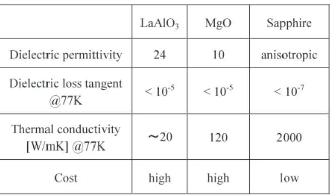
Table 1 Comparison of substrates for HTS thin-film devices.
non-adjacent coupling. Therefore, we used s of 0.35 mm andw of 0.35 mm to reduce radiation.
2.4 Design of Filter
There are three single-crystal substrates that are commonly used for fabrication of HTS thin-film devices. They are lan-thanum aluminate (LaAlO3), magnesium oxide (MgO), and
sapphire (Al2O3). These substrates are compared in Table 1.
Sapphire has several advantages, namely, low dielectric loss, high thermal conductivity at a low temperature, and a lower cost. However, sapphire has the disadvantage of anisotropic dielectric permittivity. HTS filters on r-cut substrate are promising. High-quality YBa2Cu3Oy(YBCO) films grown
on r-cut sapphire substrate are routinely obtained. It is diffi-cult to design circuits on sapphire substrate. Dielectric per-mittivity tensor on the r-cut sapphire substrate can be written as [14] ε = ⎛ ⎜⎜⎜⎜⎜ ⎜⎜⎝ 9.4 0 0 0 10.97 −0.99 0 −0.99 10.03 ⎞ ⎟⎟⎟⎟⎟ ⎟⎟⎠ (2)
Figure 7 shows the layout of a 5 GHz band 8-pole quasi-elliptic function filter with the high Qu resonator
de-scribed above. The filter used the coupling between two
Fig. 7 Layout of a 5 GHz band 8-pole quasi-elliptic function filter.
Fig. 8 Frequency response of the 8-pole quasi-elliptic function filter calculated by the moment method.
adjacent open ends and the coupling using a T-type line be-tween parallel resonators, in turn. The Qeused a T-type line
coupling. The separation between parallel resonators was about 10 mm.
In Fig. 8, frequency response of the 8-pole quasi-elliptic function filter calculated by the moment method (solid line) is shown and compared with the ideal transfer function model (dashed line). From the solid lines, it is seen that the design specifications of the filter are satisfied. The unbalanced transmission zero at the lower side of the pass-band is caused by cross-couplings among the resonators.
3. Measured Results
3.1 Filter Fabrication
The 8-pole filter, whose design is described above, is fabri-cated by using HTS YBCO thin films on a sapphire substrate (50× 56 × 0.35 mm) with a photolithography and dry etch-ing process. The photograph of the filter in a package is shown in Fig. 9.
3.2 Frequency Response
dimen-Fig. 9 Photograph of the filter package.
(a)
(b)
Fig. 10 Comparison of simulated and measured frequency response of the 8-pole quasi-elliptic function filter. (a) Narrowband response. (b) Wide-band response.
sions of 400× 400 ×250 mm. The measurement frequency response of the filter is evaluated using a vector network an-alyzer.
Figure 10 shows the measured frequency response of the 8-pole quasi-elliptic function filter. Figure 10(a) shows
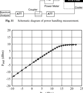
Fig. 11 Schematic diagram of power handling measurement.
Fig. 12 Measured Input/Output characteristics of the 8-pole filter.
narrowband response of the filter with center frequency of 5370 MHz and insertion loss of 2.04 dB including RF ca-ble loss was obtained, which indicated that the Qu of the
hairpin resonator reaches a value of about 40,000. The max-imum return loss in the passband is about 15 dB. The at-tenuation at f0±1.9 MHz is less than −32.9 dB. Moreover,
the transmission zeros were obtained on both sides of desir-able band. Although two transmission zeros at both sides of the transmission band are degenerate, the result is in good agreement with that of the circuit simulation and satisfied specifications.
The wideband response of the filter is measured over 5100 to 5600 MHz. As can be seen from Fig. 10(b), the spu-rious characteristic is suppressed under−60 dB.
3.3 Power Handling Measurement
Power handling capability of the developed filter was mea-sured. Figure 11 shows a schematic diagram of power han-dling measurement. Input signal is 5370 MHz continuous wave (CW), which is generated at the signal generator (SG). The CW signal is amplified at the power amplifier (PA), the gain of which is 50 dB. Input signal levels are controlled by using variable attenuator. The input and out power of HTS filter is monitored by power meter [15].
Figure 12 shows measured Input/Output characteris-tics of the developed filter. The power levels entering filter
case, the 8-pole filter is used as the receiver, the power level of which is less than 30 mW. Therefore, the power handling capability of this filter is sufficient for weather radar receiv-ing systems.
4. Conclusion
A narrowband HTS microstrip line filter with a bandwidth of 3 MHz at 5370 MHz on sapphire substrate has been devel-oped. The filter has 8-pole quasi-elliptic function character-istic. A 1.5 times wavelength microstrip hairpin resonator was adopted to suppress the radiation loss. The measured frequency response of the filter using the hairpin resonators shows a low insertion loss, sharp-cut characteristic and suf-ficient power handling capability, and these results are in good agreement with designed filter response.
Acknowledgments
The authors would like to thank Mr. H. Fuke and Mr. M. Yamazaki for their encouragement. This research was sup-ported by the Ministry of Internal Affairs and Communica-tions of Japan.
References
[1] G. Tsuzuki, S. Ye, and S. Berkowitz, “Ultra selective 22-pole, 10-transmission zero superconducting bandpass filter suppresses 50-pole Chebyshev rejection,” 2002 IEEE MTT-S Int. Microwave Symp. Dig., TH4E-2, June 2002.
[2] K. Dustakar and S. Berkowitz, “An ultra-narrowband HTS bandpass filter,” 2003 IEEE MTT-S Int. Microwave Symp. Dig., pp.1881– 1884, June 2003.
[3] J.S. Hong and P.E. McErlean, “Narrow-band HTS filter on sapphire substrate,” 2004 IEEE MTT-S Int. Microwave Symp. Dig., pp.1103– 1106, June 2004.
[4] R. Levy, “Filters with single transmission zeros at real or imagi-nary frequencies,” IEEE Trans. Microw. Theory Tech., vol.24, no.4, pp.172–181, April 1976.
[5] G. Matthaei, L. Young, and E.M.T. Jones, Microwave Filters, Impedance-Matching Networks, and Coupling Structures. Artech House, Norwood, MA, 1980.
[6] E.J. Denlinger, “Losses of microstrip lines,” IEEE Trans. Microw. Theory Tech., vol.28, no.6, pp.513–522, June 1980.
[7] H. Kayano, N. Shiokawa, M. Yamazaki, T. Watanabe, F. Aiga, and T. Hashimoto, “7 GHz-band quasi-elliptic function narrow-band su-perconducting filter on sapphire substrate,” 2006 IEEE MTT-S Int. Microwave Symp., June 2006.
[8] T. Hashimoto and Y. Kobayashi, “Frequency dependence measure-ments of surface resistance of superconductors using four modes in a sapphire rod resonator,” IEICE Trans. Electron., vol.E86-C, no.8, pp.1721–1728, Aug. 2003.
[9] G.L. Matthaei and G.L. Hey-Shipton, “Concerning the use of high-temperature superconductivity in planar microwave filters,” IEEE Trans. Microw. Theory Tech., vol.42, no.7, pp.1287–1294, July 1994.
[12] A. Morini, G. Venanzoni, and N. Iliev, “A prototype for the design of planar waveguide filters, also containing transmission zeros with close correspondence to the physical structure,” 2004 IEEE MTT-S Int. Microwave Symp. Dig., WE2A-6, pp.467–470, June 2004. [13] N. Shiokawa, H. Kayano, M. Yamazaki, T. Watanabe, F. Aiga, and T.
Hashimoto, “Ultra-narrowband HTS filter with 2.5-wavelength hair-pin resonators in 7 GHz band,” 2006 Asia-Pacific Microwave Con-ference Proceedings, pp.789–792, Dec. 2006.
[14] I.B. Vendik, O.G. Vendik, and S.S. Gevorgian, “Effective dielectric permittivity of r-cut sapphire microstrip,” 24th European Microwave Conference Dig., pp.395–400, 1994.
[15] A. Enokihara, K. Mizuno, and K. Setsune, “High-Tc supercon-ducting filter for power handling capability,” 1994 Asia-Pacific Mi-crowave Conference Proceedings, pp.1073–1076, Dec. 1994. [16] Z. Ma, E. Sakurai, and Y. Kobayashi, “Design and measurement of
a miniaturized HTS filter using microstrip spiral resonators,” IEICE Trans. Electron., vol.E88-C, no.2, pp.216–220, Feb. 2005. [17] Z. Ma and Y. Kobayashi, “Miniaturized high-temperature
supercon-ducting microstrip and coplanar waveguide filters,” IEICE Trans. Electron., vol.E88-C, no.7, pp.1406–1411, July 2005.
Tamio Kawaguchi received the B.S. and M.S. degrees in electrical and electronic systems engineering from Saitama University in 2003 and 2005, respectively. He joined Toshiba Cor-poration, in 2005. In the corCor-poration, he has been engaged in research and development of microwave superconducting filters.
Noritsugu Shiokawa received the B.S. de-gree from Tokyo University of Science, Japan, in 1995, and M.S. and Ph.D. of Science degrees from Tokyo University, Japan, in 1997, 2000, respectively, all in quantum optics. From 2000 to 2001, he was a post doctoral fellow with In-stitute for Laser Science, University of Electro-Communications, Japan, where he was engaged the research of laser cooling and atom optics. He joined Toshiba Corporation in 2001, where he was engaged in the research of quantum com-puting. Currently, he is engaged in the research and development of super-conducting device.
Kohei Nakayama received the B.S. degree in electronic engineering from Kyushu Institute of Technology in 1992 and the M.S. degree in physics from Kyushu University in 1994. In 1994, he joined the Research and Development Center, Toshiba Corporation, Kawasaki, Japan. During 2003–2005, he stayed in Superconduc-tivity Research Laboratory, ISTEC to study su-perconducting oxide device. Since 2006, he has engaged in the research of superconducting thin film growth for microwave device at the RDC, Toshiba Co. He is a member of the Japan Society of Applied Physics and the Physical Society of Japan.
Takatoshi Watanabe received the B.E. de-gree from the University of Tokyo, in 1997. He joined Toshiba Corporation, in 1997. In the cor-poration, he has been engaged in research and development of semiconductor devices and su-perconductor devices.
Tatsunori Hashimoto received the B.S., M.S., and Ph.D. degrees in electronics engineer-ing from Kyushu University, Fukuoka, Japan, in 1985, 1987, and 1990, respectively. He joined Toshiba Corporation in 1990, where he was en-gaged in the research and development of high-Tc superconducting devices. He spent three years from 1998 to 2001 at the Superconductor Research Laboratory, ISTEC, Tokyo, where he was engaged in the research and development of low-Tc superconducting analog-to-digital con-verters. Currently, he is engaged in the research and development of high-Tc superconducting devices at Toshiba Corporation. Dr. Hashimoto is a member of the Japan Society of Applied Physics.
Hiroyuki Kayano received the B.E., M.E., and Ph.D. degrees in electrical engineering from Saitama University, Saitama, Japan, in 1990, 1992, and 2005, respectively. After graduat-ing the M.S. degree, he joined the Corporate Research & Development Center, Toshiba Cor-poration, where his research activities have fo-cused on the design of power amplifiers and mi-crowave superconducting filters.