No.2. March 2012. pp. 1-14.
Introduction
Continental crust is characterized by the occur-rence of felsic magma. In most of the cases, obsidian is formed during eruption of such the felsic magma. Thus, the obsidian is quite informative to reveal an evolution of continental crust in earth history. From another point of view, the human has been used the obsidian as resources for making an artifact tool, and the indus-trial products, such as paved material and filtering ma-terial. Thus, it could be said that the obsidian has been closely related with a human life or living from ancient to present. For instance, a trace of archeological obsid-ian from acquirement to consumption becomes a good indicator to reveal human behavior during ancient times. Kuzmin (2011) indicates that distribution of the Paleolithic obsidian artifacts made of Shirataki obsidian in Hokkaido, is extended to the Sakhalin Island.
The geologist will use a chemical data for the char-acterization of a sample on the basis of
physicochemi-cal and kinetic theories (e.g. geochemiphysicochemi-cal modeling). On the other hand, the archeologist will use a chemical data for discrimination or identification on the basis of experience and/or statistic theory. Consequently, it could be said that the aim to perform a chemical analy-sis of obsidian is quite differed between the archeologi-cal research work, and the geologiarcheologi-cal research work, although the same analytical appliances, such as X-ray fluorescence (XRF) spectrometry, Laser ablation in-ductively coupled plasma mass spectrometry (LA-ICP-MS), Instrumental neutron activation analysis (INAA), and Particle induced X-ray emission (PIXE), are used in both research works. In the geological research work, a chemical data is commonly expressed by an absolute value of mass percentage, such as weight per-cent (wt.%) and parts per million (ppm). The major elements are expressed by oxides using the wt.% (SiO2, TiO2, and Al2O3 wt.% etc.), which are able to check whether or not the total amount becomes ca. 100 wt.%. On the other hand, in the archeological research work, the chemical data is generally expressed by fraction Abstract
Wave length-dispersive X-ray fluorescence (WDXRF) spectrometry was installed at Meiji University Center for Obsidian and Lithic Studies. The XRF determines the abundances of element in a material, which has been applied to the chemical analysis of archeological obsidian artifacts in order to identify a place of their sources. The WDXRF is suited to perform an accurate chemical analysis of obsidian. For the characterization of obsidian in Nagawa town area (Takayama, Omegura, and Wada touge), quantitative analysis of the obsidian by fused glass bead method was performed, and a way of nondestructive analysis for the archeological obsidian artifacts was examined. Results of quantitative analysis indicate that variation of Sr/Rb ratio and Y/Sr ratio becomes good indicator to characterize the geochemistry of obsidian, which can be theoretically explained by the fractional crystallization process of feldspars. Results of analysis using the polished, flaked and weathered surfaces of obsidian indicate that the peak-over-background method, and the way of data expression normalized to the value after a standard sample were effective to link them with the results of quantitative analysis. In this study, the polished surface of obsidian from Shirataki in Hokkaido (obstd-1) was used as the standard sample. Namely, this study suggests that the ways of analysis and evaluation using the standard sample and values, such as the obstd-1, is quite useful on the nondestructive analysis, which can directly be applied to the analysis of archeological obsidian artifacts.
Key words: obsidian, X-ray fluorescence spectrometry, chemical analysis, geochemistry, Nagawa town.
Yoshimitsu Suda
*Chemical analysis of obsidian by Wave length-dispersive
X-ray fluorescence spectrometry: application to
nondestructive analysis of archeological obsidian artifacts
* Meiji University Center for Obsidian and Lithic Studies [email protected]
of elements(%), and X-ray intensity,(counts or count per second), of a specific spectrum or line obtained from the XRF analysis. This way of data expression is enough for the discrimination of obsidian. In fact, Mochizuki et al. (1994) proposed the very effective way of discrimination diagram of obsidian using the X-ray intensity, and Ikeya (2009) demonstrated the us-age of this way of discrimination on his archeological research work. However, the problem still remaining is the results obtained from this way cannot be shared and verified among researchers.
The X-ray intensity of spectrum or line for a spe-cific element is roughly correlated with the abundance of the element. However, precisely speaking, in order to link the X-ray intensity with the actual abundances of elements in a sample, the calculations to correct the ab-sorption and excitation effects by matrix elements (i.e. matrix effect), and overlap spectrum on an analyzed spectrum or line are necessary. Moreover, the way of data expression by an absolute value (i.e. wt.% and ppm) is necessary to be shared and verified among re-searchers and research laboratories.
There are two major purposes in this study. One is how the method of geological or petrological analysis can be applied to the archeological research work. Sec-ond is how we should present the data of nSec-ondestruc- nondestruc-tive analysis to be shared among researchers. In this study, focusing on the analysis using the Wave length-dispersive X-ray fluorescence (WDXRF) spectrometry,
the way of quantitative analysis by fused glass bead method is established. Then, the geochemistry of obsid-ians in the Nagawa town area (Takayama, Omegura and Wada touge) is characterized. Finally, a way of nondestructive analysis for the archeological obsidian artifacts is examined.
1. X-ray fluorescence (XRF)
spectrometer
The XRF analysis determines the abundance of elements in a material, which has been used for the chemical analyses of rocks, minerals, sediments, soils, steels, and water. Chemical analysis of obsidian arti-facts using the XRF has been commonly performed in the archeological research work, where the purpose of analysis is generally focused on the identification for the source of obsidian artifacts (e.g. Shackley 2011). In order to establish a chemical analysis system for the archeological and geological obsidians, three types of the XRFs: WDXRF (Rigaku ZSX PrimusIII+), Ener-gy-dispersive X-ray spectroscopy (EDXRF: JEOL JSX-3100II), and Handheld or Portable X-ray spectroscopy (PXRF: Innov-X Delta Premium), was recently
in-stalled at Center for Obsidian and Lithic Studies (COLS). Among these XRFs, the WDXRF is the largest in size, which is equipped with the highest power X-ray anode (3kW Rh anode X-ray tube). The WDXRF is capable of dividing the X-ray photons according to a specific
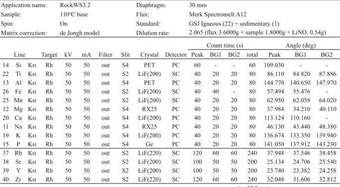
Application name: RockWS3.2 Diaphragm: 30 mm
Sample: Flux: Merk Spectromelt A12
Spin: On Standard: GSJ Igneous (22) + sedimentary (1)
Matrix correction: de Jongh model Dilution rate: 2.065 (flux 3.6000g + sample 1.8000g + LiNO3 0.54g)
Target kV mA Filter Slit Crystal Detector Peak BG1 BG2 total Peak BG1 BG2 14 Si K Rh 50 50 out S4 PET PC 60 - - 60 109.030 - -22 Ti K Rh 50 50 out S2 LiF(200) SC 40 20 20 80 86.110 84.820 87.886 13 Al K Rh 50 50 out S4 PET PC 40 20 20 80 144.770 140.650 147.970 26 Fe K Rh 50 50 out S2 LiF(200) SC 40 40 - 80 57.494 55.476 -25 Mn K Rh 50 50 out S2 LiF(200) SC 40 20 20 80 62.950 62.058 64.020 12 Mg K Rh 50 50 out S4 RX25 PC 40 20 20 80 37.984 34.210 40.110 20 Ca K Rh 50 50 out S4 LiF(200) PC 40 20 20 80 113.124 110.160 -11 Na K Rh 50 50 out S4 RX25 PC 40 20 20 80 46.130 43.440 48.380 19 K K Rh 50 50 out S4 LiF(200) PC 40 20 20 80 136.674 133.350 139.940 15 P K Rh 50 50 out S4 Ge PC 40 20 20 80 141.050 137.912 143.230 37 Rb K Rh 50 50 out S2 LiF(220) SC 120 60 60 240 37.948 37.546 38.458 38 Sr K Rh 50 50 out S2 LiF(200) SC 100 50 50 200 25.134 24.706 25.540 39 Y K Rh 50 50 out S2 LiF(200) SC 100 50 50 200 23.740 23.382 24.258 40 Zr K Rh 50 50 out S2 LiF(220) SC 120 60 60 240 32.048 31.606 32.812 total 27.7 min
Count time (s) Angle (deg) Line
energy or wavelength by a higher resolution. There-fore, the WDXRF is best suited to carry out a quan-titative analysis by accuracy of a high degree. On the other hand, the EDXRF and PXRF are equipped with the 50W Rh anode ray tube, and 0.5W Rh anode X-ray tube, respectively. Although resolution of spectrum is inferior to those of the WDXRF, the smaller size of these instruments helps to handle them easily. The EDXRF can be used on a working desk. The PXRF can be used at anywhere from a laboratory to a field. Furthermore, the sample size is limited to less than 5.0cm in the case of WDXRF analysis, whereas the sample size can be several tens of centimeters size in the case of EDXRF analysis, and there is no limitation in sample size in the case of PXRF analysis. The ana-lytical appliance can be chosen on the basis of sample size and/or requirement of analytical accuracy and precision.
2. Quantitative analysis by fused glass
bead method
2-1 Instrumental conditions
Calibration lines for the analysis elements were constructed using the following geochemical reference samples from Geological Society of Japan (GSJ: JA-1, JA-2, JA-3, JB-1, JB-2, JB-3, JR-1, JR-2, JR-3, 1a, JG-2, JGb-1, JGb-JG-2, JP-1, JF-1, JF-JG-2, JH-1, JSy-1). The H2O-
(absorbed water) in a sample was released by heating at 110°C for more than 6 hour. Low dilution fused glass bead for the analysis was prepared by the following manner: a sample powder (1.6000 g) was mixed with a flux (Merck Spectromelt A12: 3.6000 g) and an oxidiz-ing reagent (Wako HNO3: 0.54 g), and kept in a plati-num crucible. The crucible was set in a high-frequency melting furnace (Rigaku Cat. No.3091A001), and fused at 1200°C for 450 seconds. The H2O- in the flux is also released by the heating at 450°C for 4.5 hours before the mixing with the sample powder. The prepared glass bead has a dilution ratio of 2.065, thickness of ca. 5mm, and a diameter of 4.0cm.
Instrumental conditions for the quantitative analy-sis are shown in table 1. The reason why the Rubidi-um, StrontiRubidi-um, Yttrium and Zirconium were chosen for the analysis of trace elements is the way of discrimina-tion of obsidian for Mochizuki et al. (1994) and Ikeya (2009) is based on the X-ray intensities of Kα and Kβ spectra of these elements. Power voltage and current condition to the X-ray anode are 50kv and 50mA, re-spectively. Analytical diameter or diaphragm of 3.0cm (maximum) was used for all measurements. Total
ana-lytical time is 27.7 minutes. The dispersive crystal of LiF(220) is chosen for the analyses of the Rb-Kα and Zr-Kα lines, while that of LiF(200) is chosen for the analyses of Fe-Kα , Mn-Kα , Sr-Kα and Y-Kα lines. Lattice spacing of the LiF(220) is relatively narrow than that of the LiF(200) expecting relatively higher
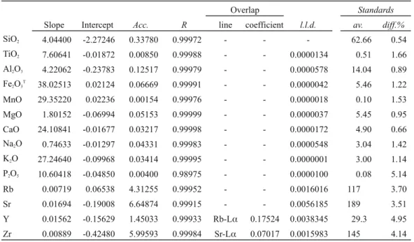
Slope Intercept Acc. R line coefficient l.l.d. av. diff.%
SiO2 4.04400 -2.27246 0.33780 0.99972 - - - 62.66 0.54 TiO2 7.60641 -0.01872 0.00850 0.99988 - - 0.0000134 0.51 1.66 Al2O3 4.22062 -0.23783 0.12517 0.99979 - - 0.0000578 14.04 0.89 Fe2O3T 38.02513 0.02124 0.06669 0.99991 - - 0.0000042 5.46 1.22 MnO 29.35220 0.02236 0.00154 0.99976 - - 0.0000018 0.10 1.53 MgO 1.80152 -0.06994 0.05153 0.99999 - - 0.0000037 5.45 0.95 CaO 24.10841 -0.01677 0.03217 0.99998 - - 0.0000172 4.90 0.66 Na2O 0.74633 -0.01297 0.04331 0.99983 - - 0.0000548 3.04 1.42 K2O 27.24640 -0.09968 0.03414 0.99995 - - 0.0000001 3.00 1.14 P2O5 10.60418 -0.04850 0.00400 0.98975 - - 0.0000100 0.08 5.14 Rb 0.00719 0.06538 4.31255 0.99952 - - 0.0016016 117 3.70 Sr 0.01694 -0.19008 6.64874 0.99915 - - 0.0056185 189 3.51 Y 0.01562 -0.15629 1.45033 0.99933 Rb-L 0.17524 0.0038345 29.3 4.95 Zr 0.00889 -0.42480 5.99593 0.99984 Sr-L 0.07017 0.0015983 145 4.14 Overlap Standards Table 2. Results of correlation lines for quantitative analysis
Acc., Accuracy; R, Correlation coefficient; l.l.d., lower limit of detection; av., mean value of standard samples; diff.%, 100 × Acc./av.; major oxides in wt.%; trace elements in ppm.
peak/background ratio (i.e. S/N ratio) and resolution, whereas requiring relatively longer analytical time for keeping the same accuracy.
Results of constant numbers of the calibration lines for the analysis elements are shown in table 2. Coef-ficient values for the correction of matrix effect were calculated on the basis of Fundamental Parameter (FP) method, in which the de Jongh model (i.e. self-absorp-tion model) was chosen for calculaself-absorp-tion, and the Ig (ig-nition loss) was regarded as base. This calculation was carried out using the PC program equipped with the ZSX PrimusIII+. Coefficient values for the correction of overlap spectra on analysis lines, Rb-Lα spectrum on Y-Kα line, and Sr-Lα spectrum on Zr-Kα line, were
also calculated using the PC program equipped with the ZSX PrimusIII+. In addition to these, corrections of the absorption effects by the flux, ignition loss, gain on ignition, and dilution rate in the glass beads were also taken into account for the calculations. The results of constructed calibration lines indicate that the cor-relation coefficient values are more than 0.999, and ac-curacy are less than 5.2% in all elements.
2-2 Propriety of instrumental conditions
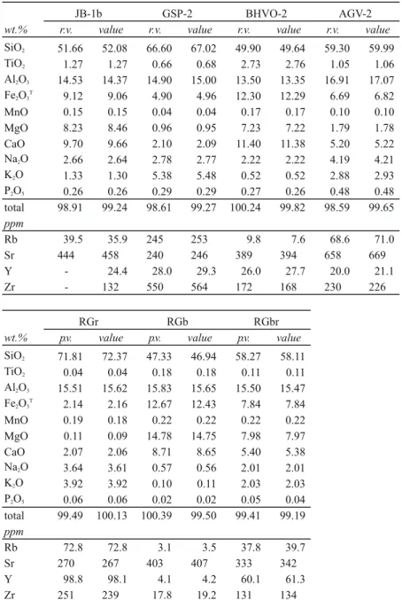
Geochemical standard samples of GSJ (JB-1b) and USGS (GSP-2, BHVO-2 and AGV-2) were analyzed to check the propriety of the analytical method. Further-wt.% r.v. value r.v. value r.v. value r.v. valueSiO2 51.66 52.08 66.60 67.02 49.90 49.64 59.30 59.99 TiO2 1.27 1.27 0.66 0.68 2.73 2.76 1.05 1.06 Al2O3 14.53 14.37 14.90 15.00 13.50 13.35 16.91 17.07 Fe2O3T 9.12 9.06 4.90 4.96 12.30 12.29 6.69 6.82 MnO 0.15 0.15 0.04 0.04 0.17 0.17 0.10 0.10 MgO 8.23 8.46 0.96 0.95 7.23 7.22 1.79 1.78 CaO 9.70 9.66 2.10 2.09 11.40 11.38 5.20 5.22 Na2O 2.66 2.64 2.78 2.77 2.22 2.22 4.19 4.21 K2O 1.33 1.30 5.38 5.48 0.52 0.52 2.88 2.93 P2O5 0.26 0.26 0.29 0.29 0.27 0.26 0.48 0.48 total 98.91 99.24 98.61 99.27 100.24 99.82 98.59 99.65 ppm Rb 39.5 35.9 245 253 9.8 7.6 68.6 71.0 Sr 444 458 240 246 389 394 658 669 Y - 24.4 28.0 29.3 26.0 27.7 20.0 21.1 Zr - 132 550 564 172 168 230 226
wt.% p.v. value p.v. value p.v. value
SiO2 71.81 72.37 47.33 46.94 58.27 58.11 TiO2 0.04 0.04 0.18 0.18 0.11 0.11 Al2O3 15.51 15.62 15.83 15.65 15.50 15.47 Fe2O3T 2.14 2.16 12.67 12.43 7.84 7.84 MnO 0.19 0.18 0.22 0.22 0.22 0.22 MgO 0.11 0.09 14.78 14.75 7.98 7.97 CaO 2.07 2.06 8.71 8.65 5.40 5.38 Na2O 3.64 3.61 0.57 0.56 2.01 2.01 K2O 3.92 3.92 0.10 0.11 2.03 2.03 P2O5 0.06 0.06 0.02 0.02 0.05 0.04 total 99.49 100.13 100.39 99.50 99.41 99.19 ppm Rb 72.8 72.8 3.1 3.5 37.8 39.7 Sr 270 267 403 407 333 342 Y 98.8 98.1 4.1 4.2 60.1 61.3 Zr 251 239 17.8 19.2 131 134 JB-1b GSP-2 BHVO-2 AGV-2 RGr RGb RGbr
Table 3. Results of quantitative analysis of standard samples and cross check samples
value, results in this study; r.v., recommended values of standard samples; p.v., preferable values of cross check
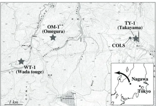
Fig. 1 Localities of obsidian analyzed in this study, and Meiji University Center for Obsidian and Lithic Studies (COLS) in Nagawa town area. Index map showing locality of Nagawa town in Japan.
Fig. 2 Photographs showing polished slab surface (a-d), flaked surface (e), weathered surface (f, g) of analyzed obsidian from Wada touge (WT-1; a, e), Omegura (OM-1; b, d, g), and Takayama (TY-1; c, f). Circles indicate analytical points by WDXRF.
more, samples of RGr, RGbr and RGb reported in Suda et al. (2010; 2011), and Suda and Motoyoshi (2011) were also analyzed for cross checking purpose. The re-sults of analysis are shown in table 3. The analysis was repeated three times for each sample. The values were estimated from the average of all the analyses. The results indicate that the difference between the analyti-cal values and the recommended or preferable values is generally less than 5%. Largest difference is shown in the Rubidium content of the BHVO-2, where the dif-ference reaches up to 26%.
2-3 Analysis of obsidian
2-3-1 Sample description and preparation
Analyses of geological obsidian from Shirataki (ob-std-1), Takayama (TY-1), Omegura (OM-1) and Wada touge (WT-1) were performed. Locality of the samples excluding the Shirataki is shown in fig. 1. Appearances of the analyzed samples are shown in figs. 2 and 3. Only the locality of obsidian from Shirataki is not ex-actly known, which could be derived from Shirataki in Hokkaido, and has been displayed in the entrance of COLS building as a monument. Therefore, this obsidian is called obstd-1 in this study. The appearance of the obstd-1 is characterized by homogeneous black-colored glass without any inclusion, such as fragments of rocks, and bubbles formed by a sparkling of magmatic gas.
On the other hand, the TY-1, and OM-1 contain some small inclusions, and the WT-1 has typical foliated tex-ture.
Sample preparation for analysis was carried out by the following manner. 1) Sample was cut using a diamond saw, and a slab with a thickness of ca. 1.0cm, and the diameter of lass than 5cm was prepared. 2) Put the slab into the jaw crusher, and make them into small fragments with one or two millimeters in size. 3) Pick the fragments without any alteration and in-clusions up 10g to 20g. 4) Put the fragments into the ultra-deionized water (Millipore Direct-Q UV), and wash them using the ultrasonic cleaning machine until the water becomes completely clear. 5) Dry the frag-ments using an oven at 110°C for more than 2 hours. 6) Make the fragments into powder using a steel mortar, and an agate mortar. 7) The powdered samples are again heated using a dry oven at 110°C for more than 6 hours until the H2O- will be completely excluded. 8) Put the powder into the glass bottle, and keep them in a desiccator. Condition of humidity is kept at less than 30%.
2-3-2 Results
Results of quantitative analysis are shown in table 4. The values of obstd-1 were estimated on the basis of the analysis using five fused glass beads. The analysis was repeated three-times in each glass bead (i.e. total Fig. 3 Photographs showing weathered surface (a), flaked surface (b), and polished sawn surface (c, d) of analyzed obsidian
fifteen times of analysis). The values of TY-1, OM-1 and WT-1 were estimated on the basis of the analysis using the two glass beads. The analysis was repeated three times in each glass bead (i.e. total six times of analysis in each sample).
Results of the analysis are compiled in the multi-element spiderdiagram to evaluate the geochemical characteristics of the obsidian (fig. 4a). All of the val-ues are normalized by the recommended valval-ues of JR-1. The compositions of the JR-2 are shown for compari-son. The JR-1 and JR-2 are the geochemical standard reference samples of GSJ (Imai et al. 1995), which are made from the obsidian in the north of Wada touge (Wada-N) and south of Wada touge (Wada-S),
respec-tively. This diagram indicates that the profiles of TY-1,
OM-1, WT-1, and JR-2 are generally similar, but com-pletely differed from the profile of obstd-1.
Geochemical characteristics of TY-1, OM-1 and WT-1 are examined more precisely on the spiderdia-gram for selected elements (fig. 4b). Although the pat-terns of TY-1, OM-1 and WT-1 generally have similar profiles, the ratio of normalized values between RbN and SrN, and SrN and YN are slightly differed among the patterns. This suggests that geochemistry of the ob-sidian can be characterized on the basis of the Rb/Sr ratio and the Sr/Y ratio.
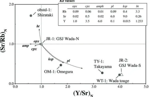
The JR-1 normalized variation diagram of Sr/ Rb ratio versus Y/Sr ratio is shown in fig. 5, in which mineral vectors indicating a compositional trend by the fractional crystallization of indicated minerals are
obstd
-1-2 obstd-1-3 obstd-1-4 obstd-1-5 obstd-1-6
wt.% value value value value value a.v. - + s.d. c.v. %
SiO2 76.50 77.11 77.16 77.24 77.95 77.19 76.44 78.03 0.4827 0.63 TiO2 0.04 0.04 0.04 0.04 0.04 0.04 0.04 0.04 0.0005 1.27 Al2O3 12.83 12.95 12.97 12.99 13.12 12.97 12.82 13.13 0.0978 0.75 Fe2O3T 1.47 1.47 1.47 1.46 1.47 1.47 1.46 1.48 0.0040 0.27 MnO 0.05 0.05 0.05 0.05 0.05 0.05 0.05 0.05 0.0000 0.00 MgO 0.01 0.01 0.01 0.01 0.02 0.01 0.01 0.02 0.0019 14.35 CaO 0.53 0.53 0.53 0.53 0.54 0.53 0.53 0.54 0.0024 0.45 Na2O 3.90 3.91 3.91 3.91 3.91 3.91 3.87 3.92 0.0111 0.28 K2O 4.57 4.56 4.57 4.57 4.58 4.57 4.56 4.58 0.0063 0.14 P2O5 0.02 0.02 0.02 0.02 0.02 0.02 0.02 0.02 0.0004 1.99 total 99.92 100.66 100.74 100.83 101.70 100.77 99.82 101.80 ppm Rb 155 151 151 150 145 151 144 158 3.8 2.5 Sr 30.1 29.6 29.4 29.2 28.1 29.3 28.0 30.2 0.7 2.5 Y 28.7 27.5 27.6 27.4 25.9 27.4 25.6 28.9 0.9 3.5 Zr 70.1 67.3 67.3 66.9 63.7 67.0 63.6 70.7 2.1 3.1
wt.% value - + value - + value - +
SiO2 77.09 76.71 77.52 76.99 76.72 77.57 76.51 76.28 76.62 TiO2 0.07 0.07 0.07 0.08 0.08 0.09 0.06 0.06 0.06 Al2O3 12.70 12.62 12.77 12.69 12.66 12.79 12.69 12.65 12.71 Fe2O3T 0.97 0.97 0.97 1.05 1.04 1.05 0.95 0.95 0.95 MnO 0.10 0.10 0.10 0.09 0.09 0.09 0.11 0.11 0.11 MgO 0.02 0.02 0.03 0.03 0.03 0.03 0.02 0.01 0.02 CaO 0.49 0.49 0.49 0.54 0.53 0.54 0.50 0.50 0.50 Na2O 3.98 3.96 4.01 3.97 3.92 3.99 4.08 4.06 4.10 K2O 4.73 4.73 4.74 4.73 4.73 4.74 4.56 4.55 4.58 P2O5 0.01 0.01 0.01 0.01 0.01 0.01 0.01 0.01 0.01 total 100.17 99.65 100.71 100.19 99.80 100.91 99.48 99.18 99.66 ppm Rb 271 264 279 256 248 261 325 320 332 Sr 8.6 8.2 9.0 13.9 13.4 14.0 8.2 8.0 8.4 Y 44.4 43.2 45.7 37.5 35.9 38.4 50.7 49.9 51.8 Zr 87.4 84.9 89.6 92.5 89.1 94.0 90.2 89.4 91.8 obstd-1-whole (Shirataki)
TY-1 (Takayama) OM-1 (Omegura) WT-1 (Wada touge)
Table 4. Results of quantitative analysis of obsidian
Fig. 4 JR-1 normalized multi-element (a) and selective multi-element (b) spiderdiagrams for obsidian.
Fig. 5 Variation of JR-1 normalized Sr/Rb ratio versus Y/Sr ratio for obsidian. Mineral vectors calculated from the partition coefficient (Kd) values (index) are also compiled. Mineral abbreviations: pl, plagioclase; ksp, K-feldspar; cpx, clinopyrox-ene; opx, orthopyroxclinopyrox-ene; amp, amphibole; bt, biotite.
also shown for comparison. Partition coefficient values between minerals and rhyolitic liquid indicate that the Rubidium is compatible with biotite (Henderson and Henderson 2009). Strontium is compatible with feldspars, while incompatible with the mafic minerals (e.g. clinopyroxene, amphibole and biotite). Yttrium is compatible with the mafic minerals, while incompat-ible with the feldspars. Namely, abundance of these elements is related with the fractional crystallization process of the minerals. Moreover, following the Ray-leigh fractional crystallization model, the Sr/Rb ratio decreases by the fractional crystallization of feldspars, while increases by the fractional crystallization of mafic minerals. On the other hand, the Y/Sr ratio in-creases by the fractional crystallization of feldspars, while decrease by the fractional crystallization of mafic minerals.
On the variation diagram shown in fig.5, the JR-1 is plotted in the point across the lines of x=1.0 and y=1.0. The obstd-1 is plotted in the field of higher Sr/ Rb ratio and lower Y/Sr ratio. The TY-1, OM-1 and WT-1 are plotted in the field completely away from the points of obstd-1 and JR-1, in which the TY-1, OM-1 and WT-1 are plotted in the field of lower Sr/Rb ratio and middle to higher Y/Sr ratio. The WT-1 is almost over-lapped with the point of JR-2. The composition of TY-1, OM-1 and WT-1+JR-2 are distinguishable using the value of Y/Sr ratio, in which the WT-1+JR-2 has the highest Y/Sr ratio, the OM-1 has the lowest Y/Sr ratio, and the TY-1 has the median Y/Sr ratio. Alignment of
the points from JR-1 through OM-1 and TY-1 to WT-1+JR-2 is generally correlated with the mineral vectors indicating the fractional crystallization of feldspars (i.e. ksp and pl). Namely, compositional variation of the obsidians could be related with the fractional crystal-lization process of feldspars. Needless to say, although there is a possibility that this compositional variation reflects the diversity of magma source composition, the results clearly indicate that the variation of Sr/Rb ratio versus Y/Sr ratio could become a good indicator to distinguish or characterize the geochemistry of the obsidians.
3. Examination of nondestructive
analysis
3-1 Instrumental conditions
Nondestructive analysis of obsidian is still required in many cases of archeological research work, which could be a critical reason to have been unable to per-form the quantitative analysis of archeological obsidian. To establish the nondestructive analysis, analysis using the polished slab surface was performed. Subsequently, analysis using the fractured or flacked and weathered surfaces was performed. Finally, the way of data ex-pression will be proposed to link the results of nonde-structive analysis with those of quantitative analysis.
All analyzed obsidian slabs have a thickness of ca. 1.0cm, which had been cut by a diamond saw, and
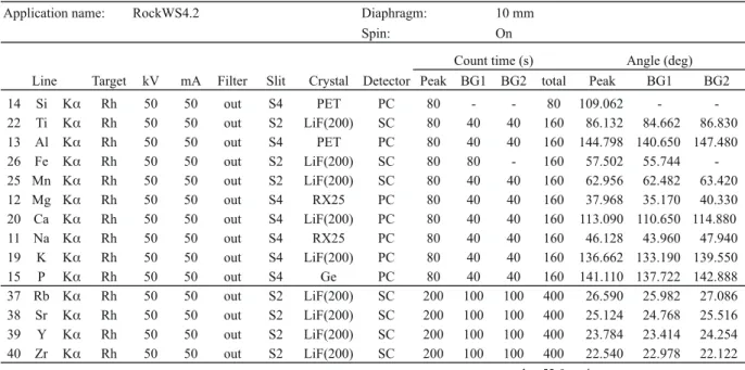
pol-Application name: RockWS4.2 Diaphragm: 10 mm Spin: On
Target kV mA Filter Slit Crystal Detector Peak BG1 BG2 total Peak BG1 BG2 14 Si K Rh 50 50 out S4 PET PC 80 - - 80 109.062 - -22 Ti K Rh 50 50 out S2 LiF(200) SC 80 40 40 160 86.132 84.662 86.830 13 Al K Rh 50 50 out S4 PET PC 80 40 40 160 144.798 140.650 147.480 26 Fe K Rh 50 50 out S2 LiF(200) SC 80 80 - 160 57.502 55.744 -25 Mn K Rh 50 50 out S2 LiF(200) SC 80 40 40 160 62.956 62.482 63.420 12 Mg K Rh 50 50 out S4 RX25 PC 80 40 40 160 37.968 35.170 40.330 20 Ca K Rh 50 50 out S4 LiF(200) PC 80 40 40 160 113.090 110.650 114.880 11 Na K Rh 50 50 out S4 RX25 PC 80 40 40 160 46.128 43.960 47.940 19 K K Rh 50 50 out S4 LiF(200) PC 80 40 40 160 136.662 133.190 139.550 15 P K Rh 50 50 out S4 Ge PC 80 40 40 160 141.110 137.722 142.888 37 Rb K Rh 50 50 out S2 LiF(200) SC 200 100 100 400 26.590 25.982 27.086 38 Sr K Rh 50 50 out S2 LiF(200) SC 200 100 100 400 25.124 24.768 25.516 39 Y K Rh 50 50 out S2 LiF(200) SC 200 100 100 400 23.784 23.414 24.254 40 Zr K Rh 50 50 out S2 LiF(200) SC 200 100 100 400 22.540 22.978 22.122 total 52.0 min
Count time (s) Angle (deg) Line
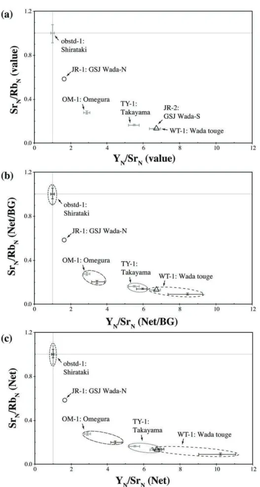
Fig. 6 Variation of obstd-1 normalized Sr/Rb ratio versus Y/Sr ratio for obsidian. Black bars indicating the quantitative value (a), correction X-ray intensity (b), and uncorrected X-ray intensity (c) for analyzed obsidian. Geochemical standard samples of JR-1 (circle) and JR-2 (trigona) (a-c), and quantitative value of analyzed obsidian (gray bars) (b-c) are compiled for comparisons.
ished by diamond paste with 0.3 micron in size (figs. 2 and 3). Instrumental conditions were completely changed from those of the quantitative analysis (table 1), which is shown in table 5. Especially, the analytical di-Especially, the analytical di-, the analytical di-ameter or diaphragm was reduced to 1.0cm to be able to choose the analytical point restricted to a homog-enous region, or prevented the analysis of inclusions. Dispersive crystal of the LiF(200) was chosen for all measurements. Total analytical time is 52.0 minutes.
3-2 Corrections of matrix effect and overlap
spectrum
Corrections of absorption and excitation effects by matrix elements (i.e. matrix effect), and overlap spectrum on an analysis line are necessary to link the analyzed X-ray intensity with actual abundances of ele-ment in a sample. The peak-over-background method proposed by Champion et al. (1966) is a method for the correction of matrix effect, which is generally used for an analysis of trace elements (e.g. Murata 1993; Kimu-ra and Yamada 1996; Motoyoshi et al. 1996). The peak-over-background method is based on a theory that the effect of matrix elements is almost the same both in the peak angle and the background angle. Thus, the matrix effect on an analyzed line will be diminished to normalize the net intensity (Net) by the background intensity (BG).
The correction of overlap spectrum on an analysis line can be combined with the peak-over-background method. The overlap coefficient values were calculated using the PC program equipped with the PrimusIII+. The analysis line for Yttrium (Y-Kα)is completely over-lapped with the Rb-Kβ spectrum, in which the ana-lyzed Y-Kα intensity (YNet) was corrected using the overlap coefficient values (BY) and analyzed Rb-K α intensity (RbNet) on the basis of the following formula: YNet–BY×RbNet.
3-3 Results
3-3-1 Polished slab surface
Representative analytical points on polished slab surfaces are shown in figs. 2a-d and 3c-d. Analysis of the obstd-1 was performed using ten surfaces of six slabs, the TY-1 was one polished surface, the OM-1 was two surfaces on two slabs, and the WT-1 was two polished surfaces on one slab. All analyses were per-formed five-times in each surface.
Variation diagrams of Sr/Rb ratio versus Y/Sr
ra-tio are shown in fig. 6. In these diagrams, the values of analyzed samples are normalized by standard values, and plotted on the basis of quantitative value (Value: fig. 6a), correction X-ray intensity by the peak-over-background method (Net/BG: fig. 6b), and uncorrected X-ray intensity (Net: fig. 6c). The standard values were obtained from the analysis of the obstd-1. Therefore, composition of the obstd-1 is predominantly plotted on the point across the lines between x=1 and y=1 in all diagrams.
The diagrams indicate that the results of correc-tion intensity (Net/BG) of analyzed obsidians are gen-erally comparable with the results of quantitative value (Value), whereas the results of uncorrected intensity of analyzed obsidian (Net) are not completely comparable with the results of quantitative value (Value). Namely, the peak-over-background method is useful to link the analyzed X-ray intensity with the actual abundance of element in these diagrams.
3-3-2 Flaked and weathered surfaces
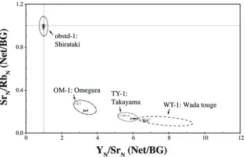
Analysis of flaked and weathered surface of obsid-ian was performed on the same method as the analysis of polished slab surface. Appearance and analytical points of the samples are shown in figs. 2e-g, and 3a-b. The samples of flaked surface were made from the obstd-1 and the WT-1, while the samples of weathered surface were made from the obstd-1, TY-1 and OM-1. The analysis was repeated five-times in each surface, and the results were compiled in the variation diagram of Sr/Rb ratio versus Y/Sr ratio (fig. 7). In this dia-gram, the analyzed X-ray intensities were corrected by the peak-over-background method, and normalized by the X-ray intensities obtained from the analysis of pol-ished surface of obstd-1.
The flaked and weathered surfaces of obstd-1, OM-1 and TY-1 are plotted within the range of the val-ues from the analysis of polished surfaces. This result indicates that the ratio of X-ray intensity between the samples is not significantly affected by the condition of analytical surfaces, although analyzed X-ray intensity will easily be affected by the condition of analytical surface. Exceptionally, only the WT-1 is plotted out of the range of the value from polished surface. Appear-ance of analytical point indicates that WT-1 is develop-ing typical foliated texture (fig. 2a). Thus, composi-tional heterogeneity on a macroscopic scale could be suggested.
4. Conclusions
4-1 Nondestructive analysis of archeological
obsidian artifacts
This study suggests that variation of Sr/Rb ra-tio and Y/Sr rara-tio is quite useful to characterize or discriminate the geochemistry of obsidian, which is theoretically supported by the fractional crystallization process of feldspars. Moreover, there are two points to link the results of nondestructive analysis with those of quantitative analysis. One is the X-ray intensity ob-tained from the nondestructive analysis must be cor-rected by the peak-over-background method. The other is the results of analysis must be expressed by the val-ues normalized to the valval-ues after a standard sample. This method is directly applied to the nondestructive analysis of archeological obsidian artifacts.
4-2 Geochemical standard sample for
nonde-structive analysis
Establishments of geochemical reference sample (i.e. standard sample) and chemical reference value (i.e. standard value) are necessary to perform the nondestructive analysis of obsidian artifacts. In this study, obstd-1 with polished slab surface was used as the standard sample that was made from the obsidian with homogeneous composition and texture. Although the obstd-1 is an ideal standard sample, a number of standard samples with various compositions are
neces-sary to improve the accuracy of the results of nonde-structive analysis. Furthermore, chemical analyses of the standard samples by multiple analytical appliances, such as ICP-MS, INAA etc., are necessary to establish the standard values. If we could accomplish the es-tablishment of the standard samples and the standard values, the nondestructive analysis of archeological ob-sidian artifacts by the XRFs will be easily performed, and the results of the nondestructive analysis are rea-sonably shared and verified among researchers.
Acknowledgments
I would like to express my sincerely thanks to Prof. S. Aida, Mr. N. Ohtake and Ms. S. Ohtake to organize the fieldwork and sampling in Nagawa town area. Special thank is extended to Ms. S. Ohtake, who permitted me to use the obsidian displayed in the entrance of the building of COLS. Prof. A. Ono, Mr. J. Hashizume, and Mr. M. Na-gai gave me effective comments as for the analyses of ar-cheological obsidian. Manuscript was improved and revised by Dr. S. Kakubuchi at Saga University, and Dr. M. Satish-Kumar at Shizuoka University. This study was supported by the Grants-in-Aid from the Educational and Research Promotion Foundation of Meiji University, and a grant of Strategic Research Foundation Grant-aided Project for Private Universities from Ministry of Education, Culture, Sport, Science, and Technology, Japan (MEXT), 2011-2016 (S1101020).
Fig. 7 Variation of obstd-1 normalized Sr/Rb ratio versus Y/Sr ratio for obsidian. Results of analyses by flaked and weathered surfaces of obsidian (black bars), and quantitative value of the obsidian after fig. 6a (gray bars) are compiled. Dashed circles indicating fields of quantitative value, and correction X-ray intensity of obsidian after fig. 6b.
References
Chanpion, K. P., Taylor, J. C. and Whittem, R. N., 1966, Rapid X-Ray Fluorescence Determination of Traces of Strontium in Samples of Biological and Geological Ori-gin. Analytical Chemistry, 38, pp.109-112.
Henderson, P. and Henderson, G. M., 2009, Earth Science data. Cambridge, 277p.
Ikeya, N., 2009, Kokuyouseki Koukogaku. Shinsensha, 306p (in Japanese).
Imai, N., Terashima, S., Itoh, S. and Ando, A., 1995, 1994 complilation values for GSJ reference samples, “Igneous rock series”. Geochemical Journal, 29, pp.91-95.
Kimura, J. and Yamada, Y., 1996, Evaluation of major and trace element XRF analyses using a flux to sample ratio of two to one glass beads. Journal of Mineralogy,
Petrology and Economic Geology, 91, pp.62-72.
Kuzmin, Y. V., 2011, The patterns of obsidian exploitation in the late Upper Pleistocene of the Russian Far East and neighbouring Northeast Asia. National Resource
En-viroment and Humans, 1, pp.67-82.
Mochizuki, A., Ikeya, N., Kobayashi, K. Mutou, Y., 1994, Isekinai ni okeru Kokuyousekisei sekki no gensanchi betu bunpu nitsuite –Numazushi Doteue iseki BBVsou no gensanchi suitei kara–. Shizuokaken Koukogaku
ken-kyu, 26, pp.1-24 (in Japanese).
Motoyoshi, Y., Ishizuka, H. and Shiraishi, K., 1996, Quanti-tative chemical analyses of Rocks with X-ray Fluores-cence Analyzer: (2) Trace elements. Antarctic Record, 40, pp.53-63 (in Japanese with English abstract). Murata, M., 1993, Major and trace elements analysis of
Korea Institute of Energy and Resources igneous rock reference samples using X-ray fluorescence spectrom-eter. Journal of Naruto College Education. 8, pp.34-50 (in Japanese with English abstract).
Shackley, M. S., 2011, X-ray fluorescence Spectrometry (XRF) in Geoarcheology. Springer, 231p.
Suda, Y. and Motoyoshi, Y., 2011, X-ray Fluorescence (XRF) Analysis of Major, Trace and Rare Earth
Ele-ments for Silicate Rocks by Low Dilution Glass Bead Method. Antarctic Record, 55, pp.93-108 (in Japanese with English abstract).
Suda, Y., Okudaira, T. and Furuyama, K., 2010, X-ray fluo-rescence (XRF; RIX-2100) analysis of major and trace elements for silicate rocks by low dilution glass bead method. MAGMA, 92, pp.21-39 (in Japanese).
Suda, Y., Koizumi, N. and Okudaira, T., 2011, X-ray fluores-cence analysis of major, trace and rare earth elements for igneous rocks, sedimentary rocks, sediments and soil. MAGMA, 93, pp.19-32 (in Japanese).
要 旨 波長分散型とエネルギー分散型(卓上型・携帯型)の各種蛍光 X 線分析装置が明治大学黒耀石研究センター(長野県小県郡長和町) に設置された。これら分析装置を用いた考古学的石器石材の非破壊化学分析法の開発を行った。まず,波長分散型蛍光 X 線分析装置に よる低希釈ガラスビードを用いた定量分析法の確立を行い,次に,同装置を用いた黒曜石の非破壊分析法について検討した。低希釈ガラ スビードを用いた定量分析結果からは,長野県長和町地域における幾つかの黒曜石原産地(男女倉,和田峠,鷹山)の黒曜石試料は, Sr/ Rb 比とY/Sr 比がそれぞれ明瞭に異なり,地球化学的手法によるモデル計算から,マグマからの斜長石の分別結晶作用の程度の違いが 反映されているものと示唆された。さらに,非破壊化学分析法の検討からは,Peak-over-background 法による共存元素の吸収励起効果 の補正,Y-K α線に対する Rb-K βのスペクトルの重なり補正を行うことで,標準試料(北海道白滝地域の黒曜石)との相対値として,定 量分析値とおおよそ直接的に対比できる結果が得られることが明らかとなった。すなわち,標準試料とその化学分析値を基準とした分析法, 解析法は,特に非破壊分析において有効であり,考古学的石器石材の化学分析法へ直接的に適用することができる。 キーワード:黒曜石,蛍光 X 線分析装置,化学分析,地球化学,長和町
隅 田 祥 光
波長分散型蛍光 X 線分析装置を用いた黒曜石の化学分析
─ 考古学的石器石材の非破壊化学分析法の開発 ─
No.2. March 2012. pp. 15-35.
はじめに
表題について着目した背景には,以下の二つの論点が ある。①中部高地霧ヶ峰黒曜石原産地地帯における地下 採掘活動の起源が,今のところ,出現期石鏃石器群(縄 文時代草創期多縄文系土器群)の時期に求められること を明らかにしている(長門町教育委員会・鷹山遺跡群調 査団編 2000,及川 2006・2008b)。②同時期の石鏃大量 製作址である長野県諏訪湖底曽根遺跡において,黒曜石 を含む特定石材と特定石器形態(型式)との結びつきが 捉えられる(藤森 1960,及川 2009a・b)。この二つの 論点は,黒曜石の地下採掘活動の起源がどこまでさかの ぼる可能性があるのか(技術的系譜),さかのぼり得る とすれば,どのような背景が考えられるのか(社会的動 機),という課題を提起する。 本論ではこの課題について,原産地遺跡と周辺地域の 遺跡群の形成という脈絡のもとに検討する必要があると 考え,とりわけ蛍光 X 線分析装置による産地推定分析 によって「和田群」と判別される黒曜石と杉久保型ナイ フ形石器石器群との関係を中心に考察する。主な方法と しては,①原産地での黒曜石原石の産出状況,②遺跡で の利用状況としての遺跡出土石器群の礫面の特徴と原石 形状,そして行使される技術的特徴,③原産地での原石 の獲得方法の三点に着目する。1.和田群黒曜石原産地における原石の
産出状況と獲得方法
日本列島の黒曜石原産地を代表する一つに長野県中部 高地霧ヶ峰一帯が挙げられる。本地域は考古学的な調査 研究の端緒となっている(鳥居 1924)。現在確認できる 黒曜石の産出地点は,和田峠を中心に点在する(図 1 左 上)。小深沢や東餅屋,星ヶ塔などは岩脈や噴出口と考 えられる大規模な露頭や地下に埋没した黒曜石鉱脈が観 察できる(杉原・小林 2004,宮坂 2006)。これに対し, 要 旨 本論では,黒曜石の地下採掘活動の起源がいつであり,その技術的系譜や社会的な動機はどこに求められるのかという 課題に対し,中部高地霧ヶ峰黒曜石原産地地帯における和田群黒曜石と,信越地域に分布する杉久保型ナイフ形石器石器 群との関係から考察した。津南地域の遺跡や野尻湖遺跡群における当該石器群を対象として,とりわけ,和田峠西産の漆 黒黒曜石の利用状況と石器製作技術について分析した。 その結果,原産地において板状原石を集収・選別し,長軸の小口面から剥離される縦長剥片の形状を活かして杉久保型 ナイフ形石器と神山型彫器を製作していたことを捉えた。そして黒曜石素材の一括搬入地点として新潟県下モ原Ⅰ遺跡と 野尻湖遺跡群上ノ原遺跡を位置付け,運搬ルートの形成を導いた。結論として,杉久保型ナイフ形石器石器群に認められ る黒曜石原石の直接採取の行動を分業的な遠征者集団によるものと考え,黒曜石原産地開発における石器原料の目的的獲 得行動として定義した。これは両面調整槍先形尖頭器石器群,出現期石鏃石器群に共通する文化的要素であると考えた。 キーワード:黒曜石原産地,旧石器時代後半期,杉久保型ナイフ形石器及 川 穣
*旧石器時代後半期における黒曜石原産地開発の一様相
─杉久保型ナイフ形石器の製作技術と和田群黒曜石の獲得と消費─
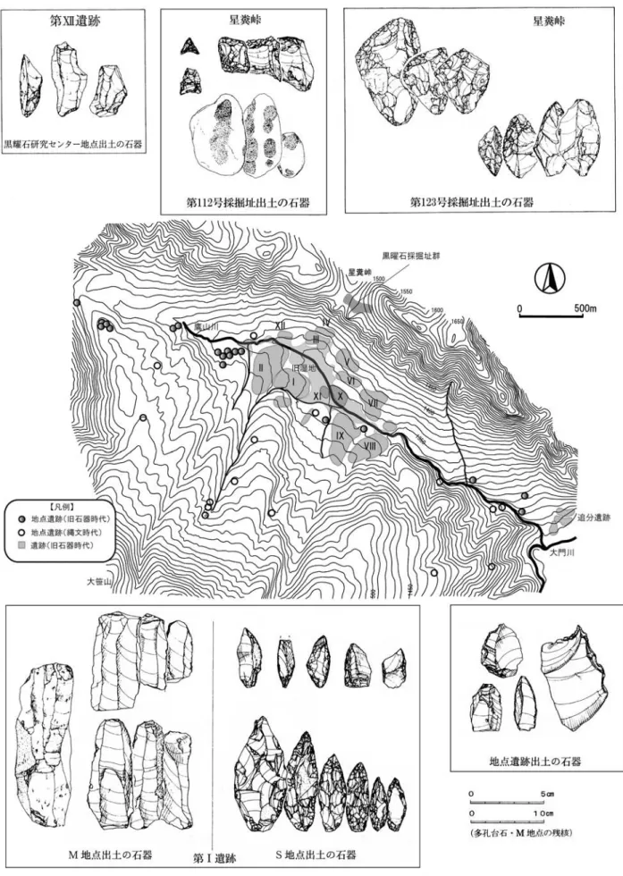
* 東京国立博物館 学芸研究部列品管理課登録室 [email protected]盆地地形の鷹山は,虫倉山斜面から盆地中央を流れる鷹 山川にかけて黒曜石が分布する。そして,男女倉谷に面 して広がる牧ヶ沢,高松沢,ブドウ沢,あるいは霧ヶ峰 南側に位置する観音沢,星ヶ台などの産出地では,拳大 からズリと呼ばれる小粒の黒曜石が河床や地表面に分布 する状況が確認できる。これらの産地のほとんどに人類 活動の痕跡が認められる。例えば,高松山斜面から男女 倉川に黒曜石転石が広がる男女倉谷では,男女倉川に 沿って点々と遺跡が存在し,男女倉遺跡群を形成する。 星ヶ塔においては,地表から地下へともぐる黒曜石の岩 脈を直接掘り込んだ採掘痕跡(縄文時代前期・晩期)が 確認されており(宮坂 2006,宮坂・田中編 2008),この 採掘址に近接して星ヶ塔のりこし遺跡が立地する。崖錐 堆積物や河川域の転石が広がる砥川林道や丁子沢には近 接して丁子沢西遺跡が立地する。 これらをみると,転石を直接採取することで黒曜石原 産地と結びつく遺跡と,地下採掘を伴って原産地と結び つく遺跡という二つの遺跡の在り方がわかる。考古学的 な意味での原産地とは,石材が単にそこにあるだけでは なく,その場にどれだけ先史人類の働きかけが痕跡とし 図 1 霧ヶ峰黒曜石原産地の位置と和田峠西産漆黒黒曜石製石器群の分布(カシミール 3D 50m メッシュ標高を用いて作成)
て認識できるのか,フィールドワークを通じてはじめて 位置づけられることになる。以下に,開発と利用が具体 的に捉えられつつある「和田群」黒曜石原産地の二つの 状況に着目する。
1-1 鷹山星糞峠における黒曜石の産出状況
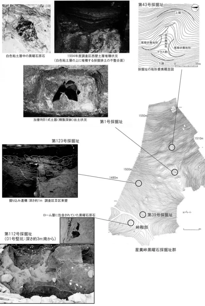
鷹山遺跡群は,3km 前後四方の盆地に規模の大小様々 な 30 ほどの遺跡が立地して構成される(図 2)。黒曜石 の原石は,盆地北辺の一角を形成する虫倉山斜面から星 糞峠,そして盆地中央の鷹山川河床にかけて分布する。 原石の獲得においては,この河床と虫倉山斜面という, 大きく二つの産出状況から捉える必要がある。 これまでの調査によって,旧石器時代における河床礫 に対する働きかけの例として,盆地中央を取り囲むよう に分布する第Ⅰ遺跡から第 XⅡ遺跡,なかでも第Ⅰ遺跡 M 地点と S 地点が具体的な内容を示す(長門町教育委 員会・鷹山遺跡群 1989・1991)。 一方,虫倉山斜面に対する働きかけとしては,約 200 基におよぶ縄文時代の採掘址群(標高 1472.0m から 1546.8m,総面積約 45000m2の範囲)のうち,第 1 号, 第 39 号,第 112 号,第 123 号採掘址の調査成果によっ て示すことができる(図 3)。星糞峠における黒曜石原 石の産出状況を確認すると,斜面中腹の第 1 号採掘址で は,黒曜石原石が流紋岩起源の白色粘土層中に包含され ていることが確認でき,ここに到達する掘り込みの痕跡 が観察できる(縄文時代後期の加曽利 B1 式土器)(長 門町教育委員会・鷹山遺跡群調査団編 1999)。一方,斜 面中腹でも峠の鞍部により近い第 123 号採掘址(時期不 明)や峠鞍部の第 112 号採掘址,第 39 号採掘址では, 黄褐色ローム層中に原石が包含されており,これを掘り 込む掘削痕跡が確認できる(多縄文土器群,出現期石鏃 石器群第 2・3 期)(長門町教育委員会・鷹山遺跡群調査 団編 2000,安蒜ほか 2003・2005,及川 2006)。 星糞峠における旧石器時代の活動痕跡は,虫倉山斜面 緩斜面部(第 123 号採掘址)から星糞峠鞍部(第 39 号 採掘址)にも痕跡がある。いずれも槍先形尖頭器石器群 が検出されている。現在までのところ,当該期の地下採 掘活動の痕跡は捉えられていないが,板状の原石を集収 し,選別して槍先形尖頭器作りを開始するという産出 状況に対する獲得の性格を想定できる(安蒜ほか 2003, 島田ほか 2006)。1-2 和田峠西古峠口付近における黒曜石の
産出状況
和田峠西から崩落した崖錐堆積物中に含まれる黒曜石 で,その立地は分水嶺を跨ぐ中山道に面している(図 4)。 現在まで,芙蓉パーライトという工業用に黒曜石が採掘 されている場所であり,流紋岩(火道部)の周縁部に流 理構造を残して発達している黒曜石の岩脈を坑道掘りし ている(宮坂・田中編 2008)。ここから崩落し,板状になっ た黒曜石原石が周辺の斜面や沢に転石として分布してい る。 原石の特徴は,宮坂清氏の観察所見に集約される。漆 黒不透明で灰白色の球顆が点状・線状の縞となる。原礫 面はざらつくサンドペーパー状で,形状はほとんどのも のが板状を成す(宮坂 2009:21 頁)。かつて,諏訪湖底 曽根遺跡において採集された石鏃の特徴として着目さ れ,藤森栄一氏によって漆黒黒曜石と呼ばれた黒曜石で ある(藤森 1960・1960・1965)。旧石器時代においては 主体的な利用産地とはならないが,利用は後期旧石器時 代の前半期から認められる(宮坂 2009)。 現在まで本産出地に石器群(遺跡)が形成されている 状況は確認されていないが,周辺の遺跡においてその獲 得の状況を捉えることができる。古峠口から 1.3㎞下流 の焙烙遺跡や,3㎞下流の浪人塚遺跡,そして分水嶺を 北に越えた男女倉遺跡群第Ⅱ地点,同第Ⅲ地点では,主 に両面調整槍先形尖頭器に利用し,焙烙遺跡では「石刃 石器群」にも利用している。いずれも板状の原石を選択 して収集し,製作場所まで搬入したものと捉えられるが, ナイフ形石器石器群には球顆の配列がほとんどない原石 を,槍先形尖頭器石器群には球顆が流理にそって点状・ 線状の縞となっている原石を選択しており,産出状況(石 質)に応じた各々の石器形態への利用状況が想定される。1-3 蛍光 X 線分析装置による産地推定分析
における判別群
ここで重要なのが,蛍光 X 線分析装置による産地推 定分析の成果である。獲得場所の異なる鷹山星糞峠産の黒曜石と,和田峠西産の黒曜石は,現在の蛍光 X 線分 析装置(EDXRF)による元素組成の分析では分別する ことができない。いずれも「和田鷹山群(WDTY)」,「和 田小深沢群(WDKB)」,「和田芙蓉ライト群(WDHY)」 という判別群に当てはまり(望月明彦氏,池谷信之氏の 判別図による),「和田群(WD)」としてひとつの判別 群で認識し,加えて肉眼観察による原礫面の特徴や色調, 球顆などの特徴から分類していくこととなる。このよう な状況は,本論で分析対象とする新潟県津南町下モ原Ⅰ 遺跡・居尻 A 遺跡出土石器群における産地推定分析結 果において同様に指摘できる(図 5)。
2.出現期石鏃石器群,両面調整槍先形
尖頭器石器群における黒曜石原石の
獲得と消費
著者は,後に述べるように,原産地での石器原料(石材) の獲得がその後に展開するすべての石器製作工程と技術 を左右すると考える。そしてまた,協業による労働力を 必要とする地下資源の採掘という活動が,ある集団から の分業的な遠征者によるものと考え,石器原料の目的的 獲得行動として位置づけてきた(及川 2008a・2009b)。 そして,そのような行動が槍先形尖頭器石器群の時期ま で遡ることを予測した(及川 2010)。まず,その成果を 導入として紹介し,上記の原産地での原石の産出状況に 対する獲得と消費の事例をみていこう。2-1 出現期石鏃石器群
出現期石鏃石器群においては,鷹山星糞峠で採掘され た黒曜石原石が一次的な加工を施した素材剥片の状態 と,選別された板状原石の状態で周辺地域へと持ち出さ れていた(横山 2000,及川 2006)。主に,関東地域の遺 跡群(群馬県五目牛新田遺跡,同西鹿田中島遺跡,埼玉 県打越遺跡など)と,東北地方日本海側地域(新潟県室 谷洞窟下層)に分布し,原産地と消費地との間には段階 的な先後関係をもつ石器製作工程が認められる。黒曜石 の利用は,遺跡単位で在地石材とは相互に補完的な消費 を示しており,石鏃(菱形・円基鏃類)や削器類を製作 している。 そして,和田峠西産の漆黒黒曜石は,諏訪湖底曽根遺 跡を基準とする「曽根型三角鏃類」の分布によって捉え られる。本石鏃形態は,その利用が漆黒の黒曜石に偏る。 この漆黒黒曜石製の三角鏃(正三角形・先端突出形・小 形正三角形)の分布をみていくと,北信越方面,東信・ 関東方面を中心に分布する。新潟県室谷洞窟下層では小 形正三角鏃に利用しており,長野県栃原岩陰では掻器に 利用している(藤森 1997)(図 6 上)。群馬県下宿遺跡 では先端突出形石鏃と拇指状掻器に利用し,群馬県白井 十二遺跡と栃木県大谷寺洞窟Ⅲでは「椛ノ湖Ⅱ型」とで も呼ぶべき,局部磨製先端突出形石鏃と掻器に利用して いる。とりわけ,白井十二遺跡は中継地的な様相を示し ており,やや大きめの板状原石を素材に掻器を製作し, 素材となる肉厚な剥片の剥離過程を示す接合例が存在す る(図 6 下)。千葉県布佐余間戸遺跡でも三角鏃と削器 に利用している。一方,下呂石原産地と近い岐阜県椛ノ 湖遺跡Ⅱでは,「椛ノ湖Ⅱ型」先端突出形石鏃と菱形鏃 に下呂石を主体的に利用し,補助的に透明黒曜石と漆黒 黒曜石を利用している1)。 これらの石器群は,和田峠西産の漆黒黒曜石原石のう ち,小形板状の原石を収集・選別し,そのまま石器素材 としている。曽根型三角鏃や拇指状掻器,削器類につい ては表裏面に板状原石の原礫面を残存させる例が多い。2-2 両面調整槍先形尖頭器石器群
鷹山遺跡群星糞峠において,第 123 号採掘址の調査区 から出土した 3c 層上部ブロックが槍先形尖頭器石器群 における原石の獲得と消費の状況をよく示している(安 蒜ほか 2003,飯田 2006)。当該時期の地下採掘活動の痕 跡は今のところ捉えられていないが,星糞峠において原 石を集収し,板状の原石を選別して槍先形尖頭器作りを 開始するという特徴を知ることができる(図 7 上)。こ の状況は,星ヶ塔のりこし遺跡や丁子沢遺跡,八島遺跡 等でも同様であり,星ヶ塔で獲得された原石のうち,ほ ぼすべて,板状原石を選別して槍先形尖頭器を製作して いる(中村 1977・1983)(図 7 中)。 そして,和田峠西産の漆黒黒曜石を利用した槍先形尖 頭器においても,焙烙遺跡,浪人塚遺跡,男女倉遺跡群 第Ⅱ地点,同第Ⅲ地点のそれぞれで同様に板状原石(球図 5 新潟県津南町居尻 A 遺跡出土石器の蛍光 X 線分析装置による産地推定分析結果(佐藤・山本編 2006 より) 居尻A遺跡出土黒曜石製石器の産地推定分析結果 No. 推定産地 産地記号 点 数 出現率 16 1 和田鷹山群 WDTY 54 38.60% 16 2 和田小深沢群 WDKB 4 2.90% 16 3 和田土屋橋北群 WDTK 6 4.30% 16 4 和田土屋橋西群 WDTN 5 3.60% 16 5 和田土屋橋南群 WDTM 2 1.40% 16 6 和田芙蓉ライト群 WDHY 37 26.40% 17 - 諏訪星ヶ台群 SWHD 13 9.30% - - 推定不可 - 13 9.30% - - 風化 - 6 4.30% 合 計 140 100%
顆が点状・線状の縞となっているもの)を選別して遺跡 内に搬入し,槍先形尖頭器を製作している(図 7 下)。 また,和田峠西産の漆黒黒曜石を利用した小形の槍先 形尖頭器が,湯ヶ峰下呂石原産地においても出土してい る(図 7 下)。この事例は上記の出現期石鏃石器群,後 に考察する杉久保型ナイフ形石器石器群と比較する上で 重要となる。
2-3 特定の形状と質の原石の獲得行動
ここまで述べてきたように,出現期石鏃石器群と両面 調整槍先形尖頭器石器群には石器素材の用い方に共通性 を認めることができる。特定の原石形状,つまり板状原 石の獲得とその素材に対し,面的な調整加工を施すとい う特徴である。原産地において板状の原石を選別して用 意し,角礫の平らな側面を打面として長軸の場合でも対 向する端部にまで届くような面的な剥離を行う。この器 体の厚さを減じる工程は,素材形状を活かして,その工 程初期でほとんど完了する。この原形とも捉えられる素 材をもとに縁辺の加工を中心に整形していく。完成され た石器には先の工程初期の剥離面を大きく残すことが多 い。また板状原石の原礫面を表裏両面に残している例も 多く認められる。 出現期石鏃石器群における黒曜石原石の地下採掘活動 と素材獲得のための一次加工と,左右非対称形槍先形尖 頭器石器群(東内野型尖頭器)における槍先形尖頭器原 形の作出は,主に周辺地域への搬出を目的としていた と考えられ(横山 2000,及川 2003・2006,飯田 2006), その後に展開する段階的な石器製作工程と石器の使用は 周辺地域の遺跡群において展開する。 このように,原産地における板状原石の集収,選別に はじまる石器製作工程は,素材形状と質の確保,そして 行使される技術(両面調整技術)によって目的の石器形 態へと帰結する。目的である石器形態の作出は,原料の 獲得段階からすべての工程が計画されており,両石器群 における素材の用い方は,石器器体の厚み調整の軽減と 打面確保による面的剥離の円滑な遂行を目的としていた と考えられる。3.杉久保型ナイフ形石器石器群におけ
る黒曜石原石の獲得と消費
3-1 新潟県津南町下モ原Ⅰ遺跡・居尻 A 遺
跡出土石器群の検討
さて,上記のような特定形状の黒曜石原石の獲得行動 は,どこまでさかのぼるのだろうか。はじめに触れたよ うに,その技術的系譜と社会的動機は,地下採掘活動に まで連なる要素であると考える。ここで着目するのが, 東北地方日本海側地域における杉久保型ナイフ形石器石 器群である。 当該石器群において黒曜石が利用されていることは杉 久保遺跡と貝坂遺跡(中村・小林 1958)の調査ですで に認識されていた。とりわけ貝坂遺跡出土資料には, 本論で着目する和田峠西産の漆黒黒曜石が利用されて いる2)。貝坂遺跡では,石刃 91 点,ナイフ形石器 26 点, 彫器 15 点,ノッチ 1 点,スクレイパー 12 点,残核 3 点, 剥片,スポール等 43 点の計 191 点が出土したという(中 村・小林 1958)。このうち黒曜石製は 87 点とされている。 宮坂清氏によると,漆黒黒曜石製の石器は,石刃などに 6 点確認されるという(宮坂 2009)。 一方,野尻湖遺跡群上ノ原遺跡県道地点(第 5 次調査 地点)においては,当該石器群が 3 箇所の石器集中部に 分かれ約 1,500 点出土している。利用石材は頁岩,安山 岩に加え,和田峠西産の漆黒黒曜石と湯ヶ峰産下呂石が 利用されている(中村ほか編 2008)。とりわけ,安山岩 において大形板状の剥片の小口面から縦長剥片を剥離し ている様相を捉えることができる。和田峠西産の漆黒黒 曜石については以下に論じる居尻 A 遺跡,下モ原Ⅰ遺 跡と同様な特徴を指摘でき,選別された板状原石の搬入 が想定できる。 居尻 A 遺跡では,5 つの石器集中部が検出され,ナ イフ形石器 28 点,彫器 35 点,縦長剥片 79 点(微細剥 離痕をもつもの含む),彫器削片 41 点,剥片 34 点,残 核 4 点,原石 2 点を含む計 286 点が出土した(集中部外 出土含む)。黒曜石は 200 点と約 70% を占める。下モ原 Ⅰ遺跡との遺跡間接合の事例が検出され,居尻 A 遺跡 から出土して下モ原Ⅰ遺跡の石器と接合した剥片がいず図 6 出現期石鏃石器群における板状原石の利用 長野県北相木村 栃原岩陰遺跡下層の石器群 ( 藤森 1996・1997)
群馬県渋川市白井十二遺跡出土の和田峠西古峠口産漆黒黒曜石 ( 斉藤 2009 より )
長野県諏訪市諏訪湖底曽根遺跡採集(漆黒黒曜石製) の曽根型三角鏃未完成品模式図
図 7 槍先形尖頭器石器群における板状原石の利用 鷹山遺跡群星糞峠第 112 号採掘址 01 号堅坑出土 (長門町教育委員会・鷹山遺跡群調査団 2000 より) 下諏訪町星ヶ塔のりこし遺跡出土(宮坂・田中編 2008 より) 長和町男女倉遺跡第Ⅱ地点出土 和田峠西産漆黒黒曜石製(中村 1977 より) 長和町男女倉遺跡第Ⅲ地点出土 和田峠西産漆黒黒曜石製(中村 1983 より) 岐阜県湯ヶ峰下呂石原産地採集の 和田峠西産漆黒黒曜石製 (白石・長澤 2008 より)
れも石器の素材とはならない不定形な剥片であることか ら,石核自体が携帯され移動し,彫器(下モ原Ⅰ遺跡) とその削片(居尻 A 遺跡)の接合例についても居尻 A 遺跡からは削片しか出土しないことを合わせて,両遺跡 の関係を「ベースキャンプ」と「ワークキャンプ」との 間の行き来として考察されている(佐藤ほか編 2000)。 新潟県津南町下モ原Ⅰ遺跡(図 8 ~ 10)では,9 つの 石器集中部から 683 点が出土しており,表 1 のような組 成である。黒曜石製石器群は 452 点出土し,全体の約 65% を占める。その他の利用石材は,清津川上流部付 近で採取可能とされる光沢のない泥質の白色頁岩を主体 とする。和田峠西産の漆黒黒曜石は,報告書による母岩 別分類の 617 ~ 622 番に分類されたものが対応する3)。 ナイフ形石器 27 点,彫器 31 点,縦長剥片 53 点,二次 加工剥片 2 点,剥片・砕片 42 点,彫器削片 21 点,残核 1 点,原石 1 点である。 とりわけ原料の搬入状況と素材の利用状況に着目した い(図 9・10)。ナイフ形石器の形態にはいくつかのバ ラエティが存在するものの,基本的には細身の縦長剥片 を素材として先端と基部のみに二次加工を施して細身柳 葉形の形態を作出しているものを中心としている。彫器 はナイフ形石器と共通した縦長剥片に加え,やや厚めの 縦長剥片や小形の剥片を素材としている。 黒曜石の搬入状況は,原石段階からの製作を示す事例 が認められる。縦長剥片の背面には,主要剥離面に対向 する剥離面を残すものが数点認められるものの,主体で はない。多くは単設打面による同一方向からの剥離作業 面を形成している。これに交差するような石核調整はほ とんど認められない。さらに漆黒黒曜石の礫面の残存状 況について着目すると,観察できた資料のみではあるが, 礫面はナイフ形石器 19 点中 8 点,彫器には 20 点中 12 点, 縦長剥片には 23 点中 18 点に残存している。図 8 の 2 や 図 9 の 12 ~ 16 のように剥片の側面や捻れた末端に礫面 を残すものが多い。 これらのことから,和田峠西産の漆黒黒曜石は,長軸 10cm 前後程度の比較的小形の板状原石を素材にその小 口面から縦長剥片を連続的に剥離していることが捉えら れる(図 9 の 15 ~ 17)。縦長剥片の剥離工程の比較的 早い段階に剥離された縦長剥片についても石器の素材と しており,石器や縦長剥片の背面に残る稜線もきりたっ たものはほとんど無く,小口面からの縦長剥片の剥離過 程の特徴を示していると考えられる。この小口面から縦 長剥片を剥離する特徴は和田峠西産以外の黒曜石(透明 黒曜石)についても主体的であることがわかる(図 10 の 19)。 また,図 8 の 20・21 のナイフ形石器は,赤色を呈す る黒曜石を利用しており,鷹山星糞峠産の可能性が高 い。ここで重要なのが,利用している黒曜石の産地(判 別群)である(図 5)。居尻 A 遺跡出土資料の分析では, 判別可能な 121 点中 13 点が諏訪星ヶ台群で,和田鷹山 群,和田芙蓉ライト群を中心とした和田群が 108 点と約 9 割を占める(佐藤・山本編 2006)。肉眼観察からでは あるが下モ原Ⅰ遺跡においても同様な産地傾向が想定で きる。つまり当該石器群の石器原料である板状原石が和 田群黒曜石を主体に構成されていると言えるだろう。 最後に,石器群の分布についてみていこう。ブロック 2 と 3 に漆黒黒曜石製石器が特に集中して分布しており, 両ブロックに剥片剥離を示す接合例がある。ブロック 2 の例は縦長剥片で,ブロック 3 の例は小形剥片の目的的 剥離と考えられる。一方,透明黒曜石製の石器は,ブロッ ク 1 ~ 4,7,8 において主体をなす。縦長剥片の剥離を 示す接合個体は,ブロック 2 以外のすべてのブロックか ら検出されている。ブロック 8,9 については頁岩を主 体とした集中部と言え,ブロック 8 に縦長剥片の剥離を 示す接合個体が検出されている。 縦長剥片の作出は透明黒曜石の方が多く,残核,剥片・ 砕片の数量でも上回る。しかし,漆黒黒曜石のナイフ 形石器と彫器の点数は透明黒曜石製と拮抗する(表 1)。 このことから縦長剥片の石器(ナイフ形石器・彫器)へ の利用比率が高いと言える。これは,漆黒黒曜石の原石 形状がほぼすべて板状であり,原石の獲得の段階からそ の形状と石質が目的的に選別されていたことと深い関係 があるのではないだろうか。つまり,原石を選別するこ とで以後の石核調整の工程を省き,効率的に目的である 細身の縦長剥片を作出し,その素材形状を活かして石器 を仕上げるという特徴が想定できる。そして同時に,そ のような技術的特徴を最もよく発現し得る石器原料とし て和田峠西産の漆黒黒曜石と,その原産地での産出状況
を位置づけることができる。