SUMMARY This paper proposes a sector base station antenna for mo- bile wireless communication systems employing multiple woodpile meta- material reflectors and a multiband radiator that establishes the same beamwidth in the horizontal plane for more than two frequency bands.
Electromagnetic Band Gap (EBG) characteristics of each metamaterial re- flector can be controlled through structural parameters of the woodpile re- flector, e.g., the rod width and rod spacing. As an example of the pro- posed antenna, a design for a triple-frequency-band antenna that radiates at 800 MHz, 2 GHz, and 4 GHz is shown. The algorithm used to adjust the beamwidth of the proposed antenna is newly introduced and adjusts the beamwidth to be the same for each band using the rod width of the woodpile. A prototype of the proposed antenna has the approximately 90◦beamwidth in the horizontal plane at the three frequencies, and the measurement results agree well with the electromagnetic field simulation results.
key words: sector base station antenna, multiband antenna, metamaterial, electromagnetic band gap (EBG) characteristics
1. Introduction
Wireless communication systems must now offer higher bit rates because smartphones and tablet terminals are becom- ing increasingly popular. Wireless systems such as cellular networks commonly-utilize multiple frequency bands to ac- tualize high system capacity. In addition, cellular systems use a sector cell configuration to improve frequency effi- ciency [1].
These existing wireless communication systems need to cover the same sector cell using the same beamwidth for all the commonly-utilized frequency bands. The systems adopt multiband sector antennas with the same beamwidth to reduce the installation area for the base stations [2]–
[4]. As the number of the frequency bands increases, tra- ditional multiband sector antennas with only one metal re- flector have difficulty in achieving the same beamwidth in all commonly-utilized frequency bands. This is because of the limited degrees of freedom of the structural parameter in the antenna design. The main reason for this is that the in- crease in the number of commonly-utilized frequency bands makes it more difficult to maintain a constant electrical dis-
Manuscript received March 11, 2014.
Manuscript revised June 20, 2014.
†This authors are with NTT Access Network Service Systems Laboratories, 1-1 Hikarinooka, Yokosuka-shi, Kanagawa 239- 0847, Japan.
††This authors are with NTT Network Innovation Laboratories, 1-1 Hikarinooka, Yokosuka-shi, Kanagawa 239-0847, Japan.
a) E-mail: [email protected] DOI: 10.1587/transele.E97.C.976
tance from the metal reflector to the radiator and constant electrical size of the metal reflector for all the commonly- utilized frequency bands. To the best knowledge of the au- thors, there have been no studies on mulitband antennas that achieve the same bandwidth other than dual-band sector an- tennas. Although dual-band sector antennas with the same beamwidth are achieved in [2]–[4], still no unified design method that can be applied generally has been derived to achieve a sector antenna with the same beamwidth that cov- ers more than two bands.
Recently, metamaterials with Electromagnetic Band Gap (EBG) characteristics has drawn attention. There is a report that metamaterials were adopted in a reflector of a single-band sector antenna that consists of one reflector and a monopole antenna [5], [6]. EBG characteristics can be de- signed by optimizing the structural parameters of a metama- terial so that the metamaterial reflects the electromagnetic waves at one specific frequency and transmits the electro- magnetic waves at all other frequencies [6]. Based on this, it is possible to utilize the EBG characteristics of the meta- material to construct a novel antenna that comprises a multi- band radiator and multiple metamaterial reflectors in which the electromagnetic waves at each frequency corresponding to the resonant frequencies of the multiband radiator are re- flected. This would enable us to develop a multiband sec- tor antenna with the same beamwidth. We can achieve this novel multiband sector antenna with increased degrees of freedom in the design parameters if the configuration of the antenna is organized in such a way that each electrical dis- tance from the metamaterial reflectors to the radiator and the electrical size of each metamaterial reflector are kept constant at all resonant frequencies of the multiband radi- ator. Up to now, there have been no reported studies on an antenna configuration in which one metal reflector of a con- ventional multiband sector antenna comprising one reflector and multiband antenna was replaced with multiple metama- terial reflectors.
This paper proposes a novel multiband sector antenna with multiple metamaterial reflectors and a multiband ra- diator. As an example of the proposed antenna design, this paper describes a design for a triple-frequency-band sector antenna with the same 90◦ beamwidth that radiates at 800 MHz, 2 GHz, and 4 GHz based on electromagnetic field simulations and measurements. The three metamate- rial reflectors comprise layers of dielectric rods stacked in sequence to form a woodpile configuration and have EBG Copyright c⃝2014 The Institute of Electronics, Information and Communication Engineers
Fig. 1 Concept of multiband sector antenna employing multiple meta- material reflectors.
characteristics that reflect the electromagnetic waves at each resonant frequency of the multiband radiator that are aligned on the same axis against the multiband radiator. Design of the EBG characteristics of each metamaterial reflector is achieved through structural parameters of the woodpile re- flector, i.e., the rod width and rod spacing. The beamwidth of the proposed antenna at each band can be adjusted using the rod width of the woodpile, and an algorithm for adjust- ing the beamwidth is proposed. Measured and simulated radiation patterns for the triple-frequency-band antenna are in good agreement and show that the same beamwidth is es- tablished for each frequency band.
Section 2 presents the concept of the new multiband sector antenna that has the same beamwidth for different bands. Section 3 describes the woodpile metamaterial struc- ture and the design of the EBG characteristics. Section 4 presents the design of a triple-frequency-band antenna based on electromagnetic field simulations and the algorithm for beamwidth adjustment. In Section 5, the fabricated pro- totype of the triple-frequency-band antenna and its perfor- mance are described. Section 6 concludes the paper.
2. Concept of Multiband Sector Antenna Employing Multiple Metamaterial Reflectors
Figure 1(a) shows the concept of the proposed multiband sector antenna employing N metamaterial reflectors and a multiband radiator (or broadband radiator). The center frequency of the desired frequency band is defined as fn (f1 > f2 > ... > fN). The reflectors are square, and their side lengths areLn. The distance between the multiband ra-
diator and the front surface of each metamaterial reflector is snas shown in Fig. 1(b). The metamaterial reflectors and the multiband radiator are centered on the X-axis and parallel to the Y–Z plane. The multiband radiator lies at the origin of the X-axis. The metamaterial reflector, #N, furthest from the multiband radiator can be implemented as a metal re- flector in the proposed antenna. The configuration of the proposed antenna is organized such that each electrical dis- tance,sn, from the metamaterial reflector to the radiator and the electrical size of each metamaterial reflector,Ln, are kept constant at all resonant frequencies of the multiband radia- tor.
The metamaterial reflectors have EBG characteris- tics meaning that they can reflect/transmit electromagnetic waves according to the frequency band. EBG characteristics act as a band-stop filter or a band-pass filter. Metamaterial reflector #nreflects the electromagnetic waves of fnsimilar to a metal reflector. On the other hand, metamaterial reflec- tor #n transmits the electromagnetic waves of specific fre- quency bands (fn+1,fn+2, . . . ,fN,N>n) as through air, and its radiation pattern is omni-directional. Each metamate- rial reflector reflects/transmits different frequency bands so that the proposed antenna radiates multiple frequency bands with the same beamwidth in the horizontal plane because of the antenna configuration mentioned above.
The proposed concept yields better design prospects than those of other design concepts because when the re- flected frequency bands change or the number of frequency bands increases, we only need to change the EBG bands or increase the number of metamaterial reflectors in the pro- posed antenna to adapt to the situation.
3. Woodpile Metamaterial
3.1 Woodpile Metamaterial Structure
We apply the woodpile metamaterial [5], [7] to the reflec- tors of the proposed multiband sector antenna. A wood- pile metamaterial that is periodic in all three dimensions has wider EBG characteristics compared to other types of meta- material [8] and is appropriate for applications such as wire- less communication systems that need a broad bandwidth.
Figure 2 shows the woodpile metamaterial structure, which
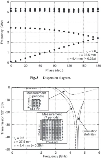
Fig. 3 Dispersion diagram.
Fig. 4 EBG characteristics of measurement and simulation results.
comprises layers of dielectric rods. They have a base of wn1×wn2 wherewn1is the rod depth along the X-axis and wn2 is the rod width along the Y-axis and Z-axis. Layer B (D) is at right angles to layer A (C) in space, and the wood- pile metamaterial consists of four layers of rods. The rods in each layer have rod spacingan. The rods in layer C (D) are set to the spacing of half ofanfrom the rods of layer A (B). The thickness (X-axis) of metamaterial reflector #nis Dn=4wn1.
3.2 EBG Characteristics Design
The EBG characteristics of the woodpile metamaterial for incident plane waves are designed using ANSYS HFSS [9].
In the electromagnetic field analysis, we simulate what the woodpile metamaterials would be in an infinite array. In this section, the rod width and spacing arew :=wn1 =wn2 and a:=an, respectively, for simplicity. The relative permittiv- ity,εr, is 9.6 and the loss tangent is tanδ =3.5×10⁻⁵ at 2 GHz. This loss tangent value is close to that in [5] and di- electric material with the permittivity of 9.6 is commercially available.
Figure 3 shows a dispersion diagram [10] of the wood-
Fig. 5 Designing center frequency of EBG using rod spacing,a.
pile metamaterial in the X-axis direction when the rod width and rod spacing are w = 9.4 mm (= 0.25a) and a = 37.5 mm, respectively. There is an EBG between 3.5 GHz and 5.0 GHz. In order to confirm the design of the EBG characteristics using the dispersion diagram, the S21 trans- mission characteristics in the X-axis direction are calculated and measured. Figure 4 shows the measurement and electro- magnetic field simulation results for the EBG characteristics in parameters same as Fig. 3. The S21 transmission charac- teristics are measured using a vector network analyzer and two microwave horn antennas based on the experimental configuration shown in [8]. The experimental configuration is arranged so that the radiated waves from the horn antenna are incident normal to the Y–Z plane of the woodpile re- flector shown in Fig. 2. Two different-sized woodpile meta- material reflectors are fabricated for the experiments. The side lengths for the two different-sized reflectors shown in Fig. 4 are 84.4 mm (three periods) and 234.4 mm (seven pe- riods). A period corresponds to the number of rods in layer A in Fig. 2. The center EBG frequencies in the measurement and simulation are in good agreement. The S21 characteris- tics degrade with a decrease in the number of periods in the metamaterial reflector; however, even a woodpile metama- terial reflector of three periods has an EBG frequency from approximately 4.0 to 5.0 GHz with respect to the band edges where the S21 characteristics cross the amplitude of trans- mission at approximately−5 dB. Similar results to that in Fig. 3 are obtained. We confirm with respect to both the dispersion diagram and the S21 transmission characteristics that the EBG characteristics are well designed for the band of approximately 4.0 GHz to 5.0 GHz. Figure 5 shows the simulated center frequency of the EBG bandwidth as a func- tion of rod spacingawhen the rod width isw=0.25a. The center frequency of the EBG bandwidth is adjusted by scal- ing the size of the woodpile metamaterial described in [5].
The center frequency becomes low when rod spacingabe- comes wider.
Fig. 6 Triple-frequency-band sector antenna employing woodpile reflec- tors.
4. Design of Triple-frequency-band Sector Antenna Employing Multiple Woodpile Reflectors
4.1 Antenna Geometry
This section describes a design example of the triple- frequency-band sector antenna (N = 3) with the same 90◦ beamwidth that radiates at 800 MHz, 2 GHz, and 4 GHz.
Figure 6 shows the configuration of the triple-frequency- band sector antenna employing multiple woodpile reflectors and a multi-band radiator. The triple-frequency-band sector antenna comprises a multiband radiator, woodpile reflector
#1 (reflects the electromagnetic waves at 4 GHz), woodpile reflector #2 (reflects the electromagnetic waves at 2 GHz), and a metal reflector (reflects the electromagnetic waves at 800 MHz). The woodpile/metal reflectors and the multiband radiator are centered on the X-axis and parallel to the Y–Z plane. In this example, the metal reflector is used to reduce the radiation in the direction of the back lobe in the radiation pattern and the entire volume of the proposed antenna. The multiband radiator is separated from the reflectors by dis- tancesn, which is a quarter of the wavelength of 800 MHz, 2 GHz, and 4 GHz, i.e.,s1 =18.8 mm,s2 =37.5 mm, and s3 =93.8 mm, respectively. The side length of the wood- pile reflectors, which is square, is assumed to be approx- imately one wavelength. It is necessary to set the wood- pile reflectors so that each reflector does not overlap each
commercially-used frequency-band combination, the pro- posed antenna is designed for the three frequency bands of 800 MHz, 2 GHz, and 4 GHz.
The multiband radiator consists of a biconical antenna and dual-band sleeve dipole antenna [11]. The biconical an- tenna resonates at 4 GHz, and the dual-band sleeve dipole antenna resonates at 800 MHz and 2 GHz. The parameters for the multiband radiator are shown in Fig. 6(b). The multi- band radiator is fed using a semi-rigid cable pierced through the center of the woodpile/metal reflectors from the backside of the metal reflector. The woodpile reflector rods used in the following investigation have the same relative permittiv- ity ofεr =9.6 and a loss tangent of tanδ=3.5×10⁻⁵at 2 GHz as mentioned in Section 3.2.
4.2 Beamwidth Adjustment Algorithm
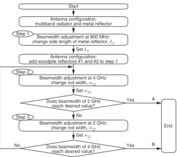
The proposed multiband sector antenna is designed so that it can be adopted into a three-sector-cell-type base station antenna. The three-sector-cell-type base station antenna adopts the same 90◦ beamwidth in the horizontal plane to suppress interference to other sectors, which is narrower than a one sector angle of 120◦. In this section, the algo- rithm for beamwidth adjustment is described for the case of the same beamwidth of 90◦ in three frequency bands. Fig- ure 7 shows a flowchart for the beamwidth adjustment al- gorithm. Beamwidth adjustment for 800 MHz is achieved by changing the side length of the metal reflector, L3, and those for 2 GHz and 4 GHz are achieved by changing the rod width,wn2, in the Y–Z plane as shown in Fig. 2.
First, the beamwidth adjustment begins with the lowest frequency of 800 MHz by changing the side length of the metal reflector,L3(step 1). It should be noted that the first adjustment is conducted for only the multiband radiator and metal reflector. Figure 8 shows the beamwidth of 800 MHz as a function ofL3. The beamwidth of 90◦for 800 MHz is obtained when the side length of the metal reflector, L3, is set to 375.0 mm. Hereafter,L3is set to be constant through- out the adjustment algorithm. Also, the parameters of the woodpile reflectors,w11,w21,a1, anda2are set to be con- stant in the following algorithm.
Next, the beamwidth is adjusted for 4 GHz by chang- ing rod widthw12 in the Y–Z plane (step 2). Hereafter, the adjustment is applied to the antenna configuration in which
Fig. 7 Flowchart of beamwidth adjustment algorithm.
Fig. 8 Beamwidth adjustment for 800 MHz (step 1).
woodpile reflectors #1 and #2 are added to the antenna con- figuration in step 1. Figure 9 shows the beamwidth for 4 GHz as a function of rod widthw12. In Fig. 9, we also observe variation in the beamwidth for 2 GHz; however, it should be noted that rod widthw22 of woodpile #2 is not changed. Asw12is increased, the beamwidth for 4 GHz be- comes wider. We find that beamwidth adjustment at 4 GHz is achieved by changingw12. The change in beamwidth at 2 GHz is less than that at 4 GHz. When the beamwidth for 4 GHz reaches the desired value, we determinew12. If the beamwidth for 2 GHz reaches the desired value, the adjust- ment ends (A in Fig. 7), and if the beamwidth for 2 GHz does not reach the desired value, the adjustment proceeds to the next step.
Finally, the beamwidth is adjusted for 2 GHz by chang- ing rod width w22 in the Y–Z plane (step 3). Figure 10 shows the beamwidth at 2 GHz as a function of rod width w22. In Fig. 10, we also observe variation in the beamwidth for 4 GHz; however, it should be noted that rod widthw12of woodpile #2 is set to the value determined in step 2 and is
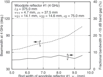
Fig. 9 Beamwidth adjustment for 4 GHz (step 2: pre-final process). Pa- rameters of reflectors areL3 =375.0 mm,w11=4.7 mm,a1 =37.5 mm, w21=14.1 mm, anda2=75.0 mm.
Fig. 10 Beamwidth adjustment for 2 GHz (step 3: final process, finished at B). Parameters of reflectors areL3 =375.0 mm,w11 =4.7 mm,a1 = 37.5 mm,w21=14.1 mm, anda2=75.0 mm.
Table 1 Reflector Parameters.
(Unit: mm)
n wn1 wn2 an sn Ln
Woodpile reflector #1 1 4.7 8.6 37.5 18.8 83.6 Woodpile reflector #2 2 14.1 14.6 75.0 37.5 164.6
Metal reflector 3 - - - 93.8 375.0
not changed. We find that rod widthw22 in the Y–Z plane can change the beamwidth for 2 GHz, as is the case with rod widthw12 in the Y–Z plane for 4 GHz. The change in the beamwidth for 4 GHz is less than that for 2 GHz. We con- firmed in another simulation that the change in beamwidth for 800 MHz is small compared to the changes in beamwidth for 2 GHz and 4 GHz and is not influenced when changing w12andw22. When the beamwidth for 2 GHz is the desired value, we setw22.
If the beamwidth at 4 GHz does not reach the desired value, the adjustment is executed again from step 2. If the beamwidth for 4 GHz reaches the desired value, the adjust- ment ends (B in Fig. 7), and if the beamwidth for 4 GHz does not reach the desired value, the adjustment is executed
Fig. 11 Change in EBG fractional bandwidth of woodpile reflector #1 as a function of rod widthw12.
Fig. 12 Change in EBG fractional bandwidth of woodpile reflector #2 as a function of rod widthw22.
again from step 2. Beamwidth adjustment is achieved for the desired beamwidth in each frequency band by repeat- ing step 2 and step 3. It should be noted that Fig. 9 and Fig. 10 show the results of the pre-final and final processes for beamwidth adjustment, respectively. The beamwidth of 90◦is achieved for each frequency band, and the parameters of the reflectors are given in Table 1. When using the triple- frequency-band antenna, we can design the beamwidth us- ing the proposed algorithm from approximately 90◦to 120◦ as shown in Fig. 8, Fig. 9 and Fig. 10.
On the other hand, Fig. 11 and Fig. 12 show simulated EBG fractional bandwidths of woodpile reflectors #1 and #2 when changing rod widthsw12 andw22, respectively. The EBG fractional bandwidth is calculated for each woodpile reflector alone in the infinite array and defined as a band gap with −10 dB edges. The EBG fractional bandwidth hardly changes in the range of rod widths shown in Fig. 9 and Fig. 10. We confirmed that the beamwidth adjustment does not influence the EBG fractional bandwidth.
Fig. 13 Overview of prototype.
Fig. 14 EBG characteristics of each woodpile reflector.
5. Measurement Results
In order to verify the design results, the triple-frequency- band sector antenna with the same 90◦ beamwidth is fabri- cated. Figure 13 shows an overview of the prototype.
Figure 14 shows the EBG characteristics of woodpile reflectors #1 and #2. It should be noted that each EBG characteristic only corresponds to each woodpile reflector.
The center frequency of the EBG band in the measurements and electromagnetic field simulations are in good agree- ment. Since a finite array (three periods) is used in the mea- surements, the S21 characteristics degrade in comparison to those in the electromagnetic field simulations in which an infinite array is considered as is the case with Fig. 4.
The measured EBG fractional bandwidth with respect to the band edges where the S21 characteristics cross the ampli- tude of transmission at approximately−5 dB and the mini- mum amplitude of the S21 characteristics for woodpile re- flector #1 are −7.5 dB and 5% (approximately 4.1 GHz to 4.3 GHz), and those for woodpile reflector #2 are −6.0 dB and 13% (approximately 2.2 GHz to 2.5 GHz), respectively.
Fig. 15 EBG characteristics of stacking two woodpile reflectors.
The S21 characteristics of the finite array (three peri- ods) are degraded as shown in Fig. 4. Most of the waves incident to the woodpile reflectors are reflected at the re- flectors in the EBG band while some of the incident waves pass through the woodpile reflectors and become undesired waves even in the EBG band due to degradation in the am- plitude of the S21 characteristics. In a similar way, most of the waves incident to the woodpile reflectors pass through the reflectors outside the EBG band while some of the in- cident waves are reflected at the woodpile reflectors and become undesired waves even outside the EBG band due to degradation of the amplitude of the S21 characteristics.
The undesired waves are reflected by the metal reflector or other woodpile reflector that has different EBG characteris- tics. The beamwidth is not determined based solely on the EBG characteristics of a single woodpile reflector. The ra- diation pattern is a composite of multi-reflected waves from the metal reflector and woodpile reflectors #1 and #2. There- fore, beamwidth adjustment of the proposed antenna using the proposed beamwidth adjustment algorithm is conducted for antenna configurations including the metal and wood- pile reflectors #1 and #2 to take into account all the reflected waves.
In order to clarify the mutual effect between woodpile reflectors #1 and #2, the S21 transmission characteristics when stacking two woodpile reflectors with different EBG characteristics are analyzed. Figure 15 shows the measure- ment and simulation results for the S21 transmission char- acteristics through woodpile reflectors #1 and #2 in the con- figuration without the multiband radiator and metal reflec- tor in Fig. 6. For comparison, the S21 characteristics of each single woodpile reflector are shown in Fig. 15. The characteristics yield the same results as the measurement results in Fig. 14. The center frequency and amplitude of the EBG characteristics in the 2 GHz band when two wood- pile reflectors with different EBG characteristics are stacked match well with those of the single woodpile reflector. On the other hand, the center frequency of the EBG character- istics in the 4 GHz band matches well with those of the sin- gle woodpile reflector. However, the amplitude of the EBG
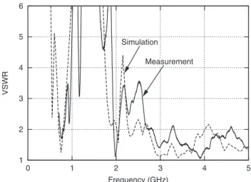
Fig. 16 VSWR of triple-frequency-band antenna.
characteristics in the 4 GHz band is broadened to improve the characteristics compared to those for the single wood- pile reflector. We also confirm that the measured results match well with the simulated results in all the frequency bands. It should be noted that the simulation results are cal- culated for the stacked woodpile reflectors based on an infi- nite array. We find that the EBG characteristics do not de- grade when stacking two woodpile reflectors with different EBG characteristics. In this paper, we discuss only a double frequency combination of commonly-utilized frequencies as mentioned in Section 3.1. The antenna design for both more than three and/or various combinations of commonly- utilized frequency bands still remains as the subject for fu- ture study. Future work is also needed to clarify the mutual effect of multiple woodpile reflectors when stacking more than two reflectors.
Figure 16 shows a comparison of simulated and mea- sured voltage standing wave ratios (VSWRs) for this triple- frequency-band antenna. The triple-frequency-band antenna achieves a VSWR<2.0 in each frequency band (800 MHz, 2 GHz, and 4 GHz) and the simulation and measurement re- sults are in good agreement.
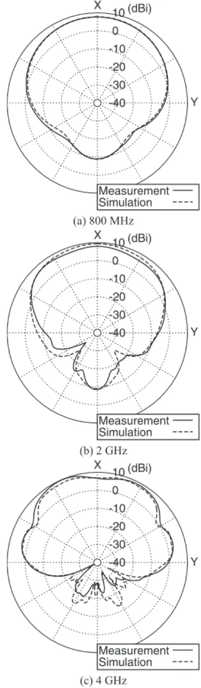
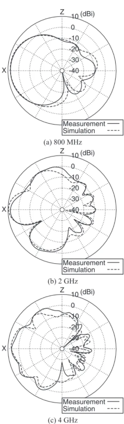
Figure 17 shows the radiation patterns in the horizon- tal plane for each frequency band. The proposed antenna has excellent directivity in each frequency band, and the measurement results match well with the electromagnetic field simulation results. Table 2 gives the beamwidth and peak gain for each frequency band. The proposed antenna achieves the beamwidth of approximately 90◦at 800 MHz, 2 GHz, and 4 GHz as designed. Moreover, the front-to- back ratio of the prototype antenna is less than−15 dB for each frequency band and is sufficient for a base station an- tenna thanks to the use of the metal reflector. We calculated the peak gain of the triple-frequency-band antenna in each frequency band when the dielectric loss tangent of the di- electric is set to zero. The calculated values of the peak gains in each frequency band are almost the same as those in Table 2. Therefore, the inherent material loss of each woodpile reflector is negligible. Figure 18 shows the radia- tion patterns in the vertical plane for each frequency band.
with a three-period rod array are not sufficient with respect to bandwidth and amplitude for the S21 characteristics as shown in Fig. 14, the performance of the radiation patterns is sufficient when a multiband sector antenna adopts two metamaterial reflectors with a three period rod array as its reflector. Improving the amplitude for the S21 character- istics is expected to suppress the unnecessary electromag- netic waves in the direction of the metal reflector (minus-X- direction) of the proposed antenna. This is because most of the waves incident to the woodpile reflectors reflect at the reflectors while some of the incident waves pass through the woodpile reflectors and become undesired waves even in the EBG band due to degradation in the amplitude of the S21 characteristics. Therefore, it is possible to reduce the effect of multi-reflected waves between the metal and/or woodpile reflectors.
6. Conclusion
We developed a novel multiband sector antenna with the same beamwidth in the horizontal plane employing multi- ple woodpile metamaterial reflectors and a multiband radi- ator for a sector base station antenna in a mobile wireless communication system. The configuration of the novel an- tenna is organized so that each electrical distance from the metamaterial reflectors to the radiator and the electrical size of each metamaterial reflector are kept constant at all reso- nant frequencies of the multiband radiator. The new antenna utilizes the EBG characteristics of the woodpile metamate- rial reflectors to achieve the same beamwidth in the horizon- tal plane at all resonant frequencies of the multiband radia- tor. The triple-frequency-band sector antenna that radiates at 800 MHz, 2 GHz, and 4 GHz was designed and its pro- totype was fabricated. We newly developed an algorithm for adjusting the beamwidth of the proposed antenna using the rod width of the woodpile. The measurement results show that the approximately 90◦beamwidth is achieved for 800 MHz, 2 GHz, and 4 GHz in the horizontal plane and the measurement and simulation results are in good agreement in each frequency band validating the antenna design. We showed that even a woodpile metamaterial reflector with only a three-period rod array has sufficient EBG character- istics with respect to the radiation pattern performance. The designs for horizontally-polarized or dual-polarized multi-
Fig. 17 Radiation patterns of the proposed multiband antenna in the hor- izontal plane.
band sector antennas are the subjects for future study.
References
[1] H. Arai and K. Cho, “Cellular and PHS base station antenna sys- tems,” IEICE Trans. Commun., vol.E86-B, no.3, pp.980–992, Mar.
2003.
[2] T. Suzuki and K. Kagoshima, “Corner reflector antenna with the same beamwidth in two frequency bands,” Electron. Commun. in Japan, vol.76, no.12, pp.64–72, 1993.
[3] Y. Ebine, “Dual frequency resonant base station antemas for PDC system in Japan,” Proc. 1999 IEEE Antennas Propag. Soc. Int.
Symp. (AP-S 1999), pp.564–567, July 1999.
[4] T. Fukasawa, H. Ohmine, K. Miyashita, and Y. Chatani, “Triple- bands broad bandwidth dipole antenna with multiple parasitic el- ements,” IEICE Trans. Commun., vol.E84-B, no.9, pp.2476–2481,
Fig. 18 Radiation patterns of the proposed multiband antenna in the ver- tical plane.
Sept. 2001.
[5] G. S. Smith, M. P. Kesler, and J. G. Maloney, “Dipole antennas used with all-dielectric, woodpile photonic-bandgap reflectors: gain, field patterns, and input impedance,” Microw. Opt. Technol. Lett., vol.21, no.3, pp.191–196, May 1999.
[6] M. P. Kesler, J. G. Maloney, B. L. Shirley, and G. S. Smith, “Antenna design with the use of photonic band-gap materials as all-dielectric planar reflectors,” Microw. Opt. Technol. Lett., vol.11, no.4, pp.169–
174, Mar. 1996.
[7] K. M. Ho, C. T. Chan, C. M. Soukoulis, R. Biswas, and M. M.
Sigalas, “Photonic band gaps in three dimensions: new layer- by-layer periodic structures,” Solid State Commun., vol.89, no.5, pp.413–416, 1994.
[8] A. R. Weily, L. Horvath, K. P. Esselle, B. C. Sanders, and T. S. Bird,
“A planar resonator antenna based on a woodpile EBG material,”
IEEE Trans. Antenn. Propag., vol.53, no.1, pp.216–223, Jan. 2005.
[9] http://www.ansys.com
[10] Y. Lee, X. Lu, Y. Hao, S. Yang, R. Ubic, J. R. G. Evans, and C. G.
Hideya So received the B.E. degree from Tokyo University of Science, Japan in 2009, and the M.E. degree from Tokyo Institute of Tech- nology, Japan in 2011, respectively. In 2011, he joined NTT Access Network Service Sys- tems Laboratories, NTT Corporation and has been engaged in research and development of antenna for future wireless access systems. He is a member of the Institute of Electronics, In- formation, and Communication Engineers (IE- ICE) of Japan and the Institute of Electrical and Electronics Engineers (IEEE).
Atsuya Ando received the B.S. degree in electronic engineering from Kitami Institute of Technology, in 1988, and the M.S. degree in in- formation engineering from Hokkaido Univer- sity, in 1990, and Dr. Eng. degrees in system information engineering from Tsukuba Univer- sity, in 2013, respectively. Since joining NTT Wireless Systems Laboratories, Nippon Tele- graph & Telephone (NTT) Corporation, Yoko- suka, Japan, in 1990, he has been engaged in research and development of personal and base station antennas for wireless mobile communication systems. From 2000 to 2003, he was with the ATR Adaptive Communications Research Labo- ratories, Kyoto, Japan, engaging in research and development on adaptive array antennas for wireless ad-hoc network systems. His research inter- ests include mobile and base station antennas for wireless communication systems and metamaterials. Dr. Ando is a member of the Institute of Elec- tronics, Information, and Communication Engineers (IEICE) of Japan and the Institute of Electrical and Electronics Engineers (IEEE).
less Symposium (2008–2013), the IEEE MTT-S International Microwave Workshop Series (2009, 2011–2012) and the IEEE Wireless Power Trans- fer Conference (2013–2014). And he was a executive committee member of the IEICE International Symposium on Antennas and Propagation(2004, 2007, 2012). He was also an associate editor of the IEICE Trans. on Elec- tronics (2008–2011). He received the 1999 Young Engineer Award from the IEICE and the 2006 Best Paper Award of the communication society of the IEICE.
Munenari Kawashima received the B.S.
and M.S. degrees in physical chemistry from Osaka University, Toyonaka, Japan, in 1995 and 1997, respectively, In 1997, he joined NTT Wireless Systems Laboratories (now NTT Network Innovation Laboratories), Yokosuka, Japan, where he has engaged in research and development on GaAs/Si MMICs and wireless devices. He is a member of the IEICE and the IEEE.
Takatoshi Sugiyama senior research engi- neer, supervisor, Group Leader in NTT Access Network Service Systems Laboratories.
Since joining NTT in 1989, he had been en- gaged in the research and development of for- ward error correction, interference compensa- tion, CDMA, MIMO-OFDM technologies for wireless communication systems such as satel- lite, wireless LAN and Cellular systems. He is currently responsible for the research and devel- opment of intelligent interference compensation technologies, radio propagation modeling and multi-band antenna design for future wireless communication systems. He currently serves the vice chair of the Technical Committee on Satellite Communications in the In- stitute of Electronics, Information and Communication Engineers (IEICE).
He is a senior member of the IEICE and a member of the IEEE.