PAPER
Special Section on Circuits and SystemsA Fast Length Matching Routing Pattern Generation Method for Set-Pair Routing Problem Using Selective Pin-Pair Connections
Shimpei SATO†a),Member, Kano AKAGI†,Nonmember,andAtsushi TAKAHASHI†,Fellow
SUMMARY Routing problems derived from silicon-interposer and etc.
are often formulated as a set-pair routing problem where the combination of pin-pairs to be connected is flexible. In this routing problem, a length matching routing pattern is often required due to the requirement of the signal propagation delays be the same. We propose a fast length matching routing method for the set-pair routing problem. The existing algorithm generates a good length matching routing pattern in practical time. How- ever, due to the limited searching range, there are length matching routing patterns that cannot find due to the limited searching range of the algo- rithm. Also, it needs heavy iterative steps to improve a solution, and the computation time is practical but not fast. In the set-pair routing, although pin-pairs to be connected is flexible, it is expected that combinations of pin-pairs which realize length matching are restricted. In our method, such a combination of pin-pairs is selected in advance, then routing is performed to realize the connection of the selected pin-pairs. Heavy iterative steps are not used for both the selection and the routing, then a routing pattern is generated in a short time. In the experiments, we confirm that the quality of routing patterns generated by our method is almost equivalent to the ex- isting algorithm. Furthermore, our method finds length matching routing patterns that the existing algorithm cannot find. The computation time is about 360 times faster than the existing algorithm.
key words: routing algorithm, set-pair routing problem, PCB, interposer
1. Introduction
In the routing design such as silicon interposer [1], [2], printed circuit board (PCB)[3],[4], FPGA[5]and etc., the combination of a pin-pair to be connected by a wire is of- ten flexible. The set-pair routing problem[6]is defined for modeling such routing designs, in which a connection re- quirement is set between a source-pin set and a sink-pin set.
In this routing problem, a length matching routing pattern while keeping wire lengths small is often required under the assumption of signal propagation delay is proportional to the wire length. Also, small computation time to generate a routing pattern is required due to the scalable requirement for the routing area.
In this paper, we propose a fast length matching method for the set-pair routing problem. Our algorithm generates a length matching routing pattern by mainly using a network flow-based algorithm, in which some restrictions for each net are set to the routing area to control the flow. Since heavy iterative steps to improve a solution is not used, our method generates a routing pattern in a short time.
A length matching routing algorithm for the set-pair Manuscript received November 28, 2019.
Manuscript revised March 28, 2020.
†The authors are with Tokyo Institute of Technology, Tokyo, 152-8550 Japan.
a) E-mail: [email protected] DOI: 10.1587/transfun.2019KEP0015
routing problem has been proposed [6] (Hereinafter, it is called the Nakatani algorithm). This algorithm generates a length matching routing pattern while keeping the total length as small as possible by improving an initial solution.
The initial solution is a minimum total length pattern gen- erated by the network flow-based algorithm[2]. The initial solution is improved by a heuristic approach to reduce the wire length differences by changing the pin-pairs to be con- nected while keeping the minimum total length. Then, small length wires are extended to realize length matching without changing the pin-pairs connected. Although the time com- plexity of this problem that minimizes the length difference of wires is not apparent, the Nakatani algorithm finds a good routing in practical computation time.
Nakatani algorithm has drawbacks of the approach of improving a minimum total length pattern. In the set-pair routing problem, a better length matching routing is some- times generated by combinations of pin-pairs that do not ap- pear in minimum total length patterns. Nakatani algorithm only searches the combinations of pin-pairs in minimum to- tal length patterns, thus it cannot find such a good routing pattern. For example in Fig. 1, (b) is a routing pattern in which pin-pairs in a minimum total length pattern are con- nected, and (c) is a routing pattern in which pin-pairs in a non-minimum total length pattern are connected. The com- putation time of the Nakatani algorithm is practical but not fast. It needs heavy iterative steps to find a small wire length difference routing pattern in minimum total length patterns.
In the set-pair routing, although pin-pairs to be con- nected is flexible, it is expected that combinations of pin- pairs which realize length matching are restricted. In our method, such a combination of pin-pairs is selected in ad- vance, then routing is performed to realize the connection of the selected pin-pairs. A routing pattern generated in this way is expected to contain many appropriate pin-pairs to realize length matching. Modification to improve such solu- tions will be small and will be performed in a short time.
As a combination of pin-pairs to be connected (Here- inafter, it is referred to as target pin-pair set), we select pin- pairs that the distances of each pin-pair are small. In the actual routing pattern, wires are routed with the affection of obstacles or other wires, and the lengths of them will be dif- ferent from the distances of each pin-pair. However, most of the pin-pairs in an ideal combination of pin-pairs that achieves length matching will be expected to have almost the same distance, that is the distance differences between them are small.
Copyright©2020 The Institute of Electronics, Information and Communication Engineers
Our routing algorithm tries to connect the target pin- pairs as much as possible. Unlike routing algorithms for general routing problems where the connection requirement is given to each pin-pairs, this routing algorithm does not guarantee the connectivity of the given pin-pairs. The target pin-pairs are candidates for achieving length matching but it will include pin-pairs that cannot connect or not in the ideal combination. The algorithm certainly generates a feasible routing pattern by modifying such pin-pairs, and a better routing pattern is expected than a routing pattern forced to connect the given pin-pairs.
Our proposal in this paper is a routing method for the set-pair routing algorithm that mainly consists of a pin-pair selection algorithm and a pin-pair connection algorithm. We have proposed a pin-pair selection algorithm[7]and a rout- ing algorithm[8]separately as conference papers. For the pin-pair selection algorithm in this paper, an improved pin- pair selection algorithm based on the previous work [7]
is proposed. For the pin-pair connection, the same algo- rithm[8]is used.
2. Set-Pair Routing Problem
The set-pair routing problem is a routing problem that con- nection requirements are given between two sets of pins, named source-pin set and sink-pin set. One pin from the source-pin set and one pin from the sink-pin set are con- nected by a wire to propagate a signal so that no pin is shared by more than one signal. All pins should be connected by wires without crossing each other.
In this paper, the routing area is represented as a single- layer grid array. Some intersections of edges are specified as source-pins, sink-pins, and obstacles. The location of these points is given as an input. An intersection except specified as an obstacle can be connected to neighboring in- tersections. A chain of connections from a source-pin to a sink-pin forms a wire.
Figure 1 is an example of set-pair routing problem.
Figure 1(a) is an input, and (b) and (c) are routing pat- terns as the different types of solution. The red rectangles {A,B,C}and the blue rectangles{X,Y,Z}represent source- pins and sink-pins, respectively. The bold lines in Fig. 1(b) and Fig. 1(c) that each line connects a source-pins and a sink-pin represent wires. In the set-pair routing, a routing pattern is said to befeasibleif each wire connects source- pin and sink-pin without using grid intersections of obsta-
Fig. 1 Example of set-pair routing problem.
cles. The existence of a feasible routing pattern is easily checked by a maximum flow algorithm [6]. Therefore, in the following discussion, we focus on the problem instances that have a feasible routing pattern.
In routing pattern generation, a routing pattern that re- alizes not only connection requirements but also small de- lays of signal propagation, small difference of signal delays, and etc. is required. Under the assumption that the signal propagation delay is proportional to the wire length, a rout- ing pattern that has small length wires and small length dif- ferences of wires is often pursued.
In the set-pair routing problem, the length matching is not easy even though the minimum total wire length is achieved in polynomial time. Even though the time com- plexity of the problem that minimizes the length difference of wires is not apparent, the problem of finding disjoint paths of the specified length or length-cap is NP-hard in gen- eral[9]. The length matching in the set-pair routing would be improved by applying length matching algorithms for or- dinary routing problems[4],[10],[11]. However, the results seem not good enough since they generate routing patterns by utilizing characteristics of problem specifications well, but without utilizing the flexibility of pin-pairs. For exam- ple, the flexibility of pin-pairs will be important in the case that some wire needs large detour to realize the fixed pin- pair connectivity in a dense routing area.
The routing pattern of Fig. 1(b) achieves a length matching by applying snaking to an initial solution of mini- mum total length. The total length of the pattern is 17, and the pattern is generated from a minimum total length pattern whose total length is 13. The routing pattern of Fig. 1(c) also achieves a length matching with the total length of 15. The maximum length difference of wires in (b) is 1 whereas in (c) is zero.
The Nakatani algorithm generates a routing pattern like Fig. 1(b) by modifying a pattern of minimum total length.
The algorithm cannot generate a pattern like Fig. 1(c) be- cause the pattern achieves the length matching in non- minimum total length. Our objective is to obtain a length matched routing pattern like Fig. 1(c).
3. Related Work: Nakatani Algorithm
In order to obtain a routing pattern that achieves length matching as much as possible in a set-pair routing problem, a heuristic algorithm is proposed [6] (Hereinafter, called Nakatani algorithm). This algorithm tries to find a length matching routing pattern while keeping the total wire length small. This algorithm firstly generates a minimum total length pattern and generates a length matching routing pat- tern by improving the initial pattern.
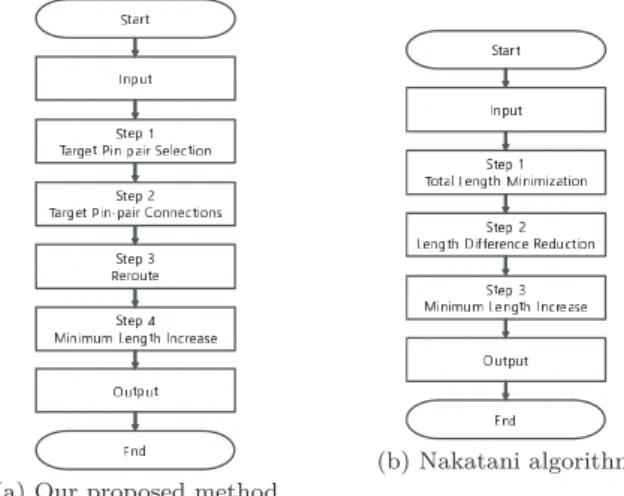
The outline of the algorithm is shown in Fig. 2(b).
(1) Total Length Minimization: A routing pattern of the minimum total length is generated as an initial solution by a minimum cost maximum flow algorithm.
(2) Length Difference Reduction: A routing pattern that achieves a small wire length difference is generated
Fig. 2 The outline of design flow for length matched routing algorithm in set-pair routing.
from the initial solution. The length differences be- tween wires are reduced by changing the pin-pairs to be connected while keeping the minimum total length of the pattern. An algorithm to find zero cost closed cycles is used for this step.
(3) Minimum Length Increase: A routing pattern that achieves length matching is generated by increasing the length of wires to match the maximum length. A snaking technique[3]is used for this step.
The Nakatani algorithm finds a good solution of length matching routing pattern but has some disadvantages.
A routing pattern of the initial solution generated in the step (1) tends to have large wire length differences, and it causes large computation time for improving a solution in the step (2). In this step, pin-pairs located nearby are connected in first because a breadth-first algorithm is used.
Therefore, the length difference of the wire firstly connected and the wire lastly connected often be large.
The step (2) requires large computation time for im- proving the initial solution. In this step, candidates of the pin-pairs to change the connection is searched. The candi- dates of the pin-pairs are found on a zero-weighted directed cycle that includes two vertices of pins. Many combina- tions of zero-weight directed cycles exist in the flow graph of the initial solution and large computation time is needed to check them. Because of the initial solution that has large wire length differences, the step (2) needs heavy iterations to improve the solution, and it is one reason for the large computation time.
Furthermore, there are length matching patterns that the Nakatani algorithm never finds them since this algorithm only searches combinations of pin-pairs to be connected in minimum total wire length patterns. The examples in Fig. 1 is one of them. The routing pattern of (b) is a solution of the Nakatani algorithm that is generated from a minimum total length pattern of which the total length is 13. After applying the snaking technique, the total wire length of (b) is finally 17, and wire length differences still remain. On the other
hand, the routing pattern of (c) achieves a length matching with no wire length difference. Also, the total wire length is 15, and it is smaller than (c).
4. Selective Target Pin-Pair Connection Method
4.1 Outline of Our Method
Our method is designed to obtain a length matching routing pattern in small computation time and also to find an optimal pattern that is not based on a pattern of the minimum total wire length. In the method, pin-pairs that are expected to achieve length matching if they are connected are roughly set before routing steps, and the routing steps try to connect the pin-pairs as much as possible. Hereinafter, a pin-pair selected before the routing steps is referred to as a target pin- pair, and a set of target pin-pairs that includes all source-pins and sink-pins is referred to as a target pin-pair set.
The flow of our method is shown in the Fig. 2(a).
(1) Target Pin-pair Selection Pin-pairs that are expected to achieve length matching if they are connected, are selected as the target pin-pair set. The connectivity of the pin-pairs is not considered. All distances between source-pins and sink-pins are measured and a combina- tion of pin-pairs in which the maximum distance is the minimum and the minimum distance is the maximum is selected.
(2) Target Pin-pair Connection A routing pattern in which the target pin-pairs are tried to connect is generated by the network flow-based algorithm [8]. The algo- rithm generates a feasible routing pattern while trying to connect the target pin-pairs as much as possible. The connection of all the target pin-pairs is not guaranteed.
Each wire is routed avoiding the area where it is ex- pected the other wires exist.
(3) Reroute Detoured wires are modified in this step. Wires that are routed avoiding the area where it is expected the other wires exist may sometimes be detour. Each wire is once ripped up and rerouted to be the length is minimum. This modification is applied to all wires one by one while keeping the pin-pairs connected.
(4) Minimum Length Increase Small length wires are ex- tended by snaking to match the maximum wire length.
The same technique with the Nakatani algorithm step (3) is used.
4.2 Target Pin-Pair Selection
Pin-pairs that the distances of each pin-pair are almost equal should be selected as the target pin-pairs. Here, pin-pairs are represented as a weighted complete bipartite graphG, where a pin is a vertex and a candidate for pin-pair is an edge with the weight of the distance of the pin-pair. A target pin-pair set is equivalent to a perfect matching of the graphG.
The selection of a pin-pair set that achieves the max- imum distance be minimum and the minimum distance be maximum is formulated as a perfect matching that achieves
the maximum-edge-weight be minimum and the minimum- edge-weight be maximum in the weighted complete bipar- tite graphG. To solve this problem, we propose a matching algorithm based on our algorithm[7], which finds a perfect matching of the maximum-edge-weight is minimum.
In the following explanation, a perfect matching where the sum of edge weights be minimum is referred to asmin- total matching, a perfect matching where the maximum- edge-weight be minimum is referred to asmin-max match- ing, and a perfect matching where the maximum-edge- weight and the minimum-edge-weight be minimum among the matching of maximum-edge-weight be minimum is re- ferred to asmin-max&diffmatching.
A min-max & diff matching is obtained by repeating the procedure of shrinking the upper bound and the lower bound of weights of matching edges. In the following steps, the step (ii) and the step (iii) are the processes of shrinking the upper bound of weights of matching edges by our previ- ous algorithm[7]. The step (iv) and the step (v) are the pro- cesses of shrinking the lower bound of weights of matching edges.
Step (i) Generate weighted complete bipartite graphsGand G0, which are the same ones. Where a vertex, an edge, and an edge weight correspond to a pin, a pin-pair can- didate, and the distance of the pin-pair, respectively.
Step (ii) Obtain a min-total matching M in the graph G.
Eliminate all edges whose weights are greater than or equal towfrom the graphG0. Where thewis the max- imum weight inM.
Step (iii) If a perfect matching exists in the graphG0, assign G0toG, and return to the step (ii). If not, go to the step (iv).
Step (iv) Obtain a min-total matching M in the graph G.
Eliminate all edges whose weights are less than or equal towfrom the graphG0. Where thewis the mini- mum weight inM.
Step (v) If a perfect matching exists in the graphG0, assign G0toG, and return to the step (iv). If not, output M and finish.
The validity of our proposed algorithm is as follows.
LetGbe the bipartite graph when the step (iv) starts. Perfect matchings inGare the min-max matching, and it is validated in the paper[7]. LetMandG0be the matching outputted by our algorithm and the bipartite graph whenMis outputted.
Also, let w be the minimum-edge-weight in M. If M is not a matching where the difference of the maximum-edge- weight and the minimum-edge-weight is minimum, that is, ifMis not optimal, then there is an optimal perfect match- ing M0, and all edge weights in M0 are larger thanw. G0 contains a perfect matchingM0sinceG0keeps all the edges whose weight is larger thanw, and the algorithm does not outputMsince there is a perfect matchingM0inG0.
An example of a weighted complete bipartite graph is shown in Fig. 3(a). Figure 3(b) is a min-total matching ob- tained from Fig. 3(a), in which the sum of weights of the matching edges is minimum. Figure 3(c) is a min-max matching obtained after applying the step (ii) and (iii), in
Fig. 3 An example of matching.
which the edges of weight 12 are eliminated from the graph and the maximum edge weight be 10 is achieved. Figure 3 (d) is a min-max & diffmatching obtained after applying all steps, in which the edge of weight 4 is eliminated from the graph and the difference of edge weights be 0 is achieved.
4.3 Target Pin-Pair Connection
This algorithm generates a routing pattern in which a given pin-pair set is connected as much as possible. Here, the al- gorithm[8]that we have proposed is used. We applied the Ford-Fulkerson algorithm [12], which is a maximum flow algorithm, to obtain a routing pattern by finding a maximum flow between the target pin-pairs.
The algorithm certainly generates a feasible routing pattern while trying to connect the target pin-pairs as much as possible. That is, if the realization of all target pin-pairs connection is difficult, it generates a routing pattern in which some pin-pairs connected are not from the target pin-pair set.
To realize a target pin-pair connection, each wire is routed avoiding the area where it is expected the other wires exist. A bounding box that is a minimum rectangle enclos- ing a target pin-pair is introduced as an estimated wiring area of the target pin-pair. Searching routing paths is pro- ceeded by detouring an area that the bounding boxes are overlapped.
In order to obtain a routing pattern by a network flow algorithm, pins and routing area are converted to a flow graph and a primary source that is connected to all source- pins and a primary sink that is connected to all sink-pins are added to the graph, then a maximum flow from the primary source to the primary sink is used as routing paths[6]. We define the degree of overlapping bounding boxes for each edge of a routing area as the number of overlapping bound- ing boxes on each edge, in which the target pin-pairs of them are not connected yet (Hereinafter, it is simply called the overlapping degree).
The following steps are the process to find a maximum flow by our algorithm.
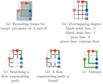
Fig. 4 Process of the target pin-pair connection.
Step(i) Update the overlapping degree for each edge in the flow graphG.
Step(ii) Search a flow augmenting path from the primary source to the primary sink ofG. Edges whose over- lapping degree is 1 are firstly searched. If a flow aug- menting path is not found, edges that the overlapping degree is larger than 1 are secondly searched. Finally, all edges including edges that the overlapping degree is 0 are searched.
Step(iii) When a flow augmenting path is found in the step (ii), send a flow along to the augmenting path, and re- turn to the step (i). If no flow augmenting path exists, output the obtained maximum flow and finish.
An example of the routing process is shown in Fig. 4.
Figure 4(a) shows the bounding boxes and Fig. 4(b) shows the degree of overlapping for each edge. Figure 4(c) and (d) show the routing process, and Fig. 4(e) is an obtained flow as a routing pattern of our algorithm. A pair of a red rectangle and a blue rectangle labeled in the same alphabet is a target pin-pair, and the current flow that already found exists in the upper right of the routing area.
A bounding box is set to a target pin-pair for which a flow augmenting path is not found yet. In the Fig. 4(a), two bounding boxes for the target pin-pairs of A and B are set.
The overlapping degrees for each edge are shown in the Fig. 4(b). The area of the black solid line is covered by the two bounding boxes of A and B, then the overlapping degree for these edges is 2. The area of the black dash line is covered by only one bounding box, then the overlapping degree for these edges is 1. The area of the gray line is not covered by any bounding boxes, then the overlapping degree for these edges is 0. The green line is the current flow, that is the flow augmenting path for this pin-pair is already found.
Figure 4(c) shows the progress of searching a flow aug- menting path using edges of the overlapping degree of 1.
The edges of the overlapping degree of 2 and 0 are not used for the searching.
Figure 4(d) shows the situation of finding a flow aug-
Fig. 5 Reroute and minimum length increase.
menting path for the target pin-pair A. The target pin-pair A can be connected by the edges of the overlapping degree of 1, then a flow augmenting path for the target pin-pair A is found earlier than for the target pin-pair B.
Figure 4(e) is the obtained flow as a routing pattern as of our algorithm. The target pin-pairs connection is achieved. Considering a simple network flow algorithm, a flow augmenting path from the source-pin of A to the sink- pin of B will be found early because the distance of them is small. On the other hand, even if a flow augmenting path between target pin-pair A is found, the path will sometimes prevent to find a flow augmenting path between the target pin-pair B depending on algorithms. Our algorithm avoids these problems by introducing a bounding box.
4.4 Reroute and Minimum Wire Length Increase
The routing pattern generated by our target pin-pair connec- tion algorithm tends to include some detoured wires because of the routing avoiding areas that the other wires will be ex- pected to use. The 3rd and 4th steps of our routing method are the modification of the routing pattern generated by our routing algorithm. An example of these steps is shown in the Fig. 5.
The Fig. 5(a) is a routing pattern generated by our rout- ing algorithm. The left wire is detoured and these two wires have length differences.
In the 3rd step, all wires are rerouted one by one to be connected in shortest route. The shortest path of a pin-pair is obtained by the Dykstra algorithm[13]where the other wires are treated as obstacles. The Fig. 5(b) is a result of this step. The length of the left wire is changed from 8 to 5 by this modification.
In the 4th step, short wires are extended by a snaking technique to realize length matching. The same technique used in the Nakatani algorithm is used for this modification.
The Fig. 5(c) is a result of this step. The length of the right wire is changed from 2 to 4. This step is iteratively applied to the pattern to be the length of all wires equal as much as possible.
The Fig. 5(d) is the final result. Both of the wire lengths is 6.
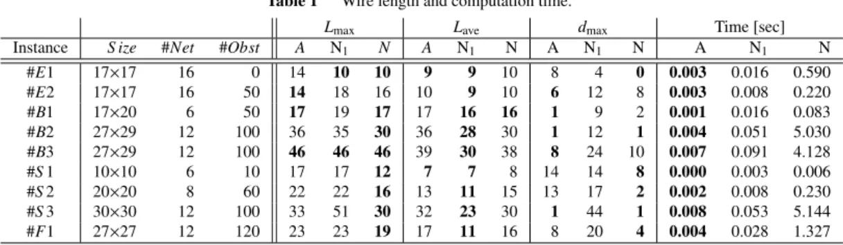
Table 1 Wire length and computation time.
Lmax Lave dmax Time [sec]
Instance S ize #Net #Obst A N1 N A N1 N A N1 N A N1 N
#E1 17×17 16 0 14 10 10 9 9 10 8 4 0 0.003 0.016 0.590
#E2 17×17 16 50 14 18 16 10 9 10 6 12 8 0.003 0.008 0.220
#B1 17×20 6 50 17 19 17 17 16 16 1 9 2 0.001 0.016 0.083
#B2 27×29 12 100 36 35 30 36 28 30 1 12 1 0.004 0.051 5.030
#B3 27×29 12 100 46 46 46 39 30 38 8 24 10 0.007 0.091 4.128
#S1 10×10 6 10 17 17 12 7 7 8 14 14 8 0.000 0.003 0.006
#S2 20×20 8 60 22 22 16 13 11 15 13 17 2 0.002 0.008 0.230
#S3 30×30 12 100 33 51 30 32 23 30 1 44 1 0.008 0.053 5.144
#F1 27×27 12 120 23 23 19 17 11 16 8 20 4 0.004 0.028 1.327
S ize,#Net,#Obst: Routing area size, # of nets, # of obstacles Lmax: Max. wire length
Lave: Avg. wire length
dmax: Max. wire length difference (Max. wire length - Max. wire length) Bold font value is the smallest one.
5. Experiments
The effectiveness of our proposed method is evaluated by comparison with the Nakatani algorithm in the following ex- periments.
• Performance of our method.
Routing patterns generated by our method are evalu- ated by comparing patterns generated by the Nakatani algorithm. Also, the computation time for pattern gen- eration is compared.
• Quality of the selected target pin-pair set.
How our algorithm selects appropriate pin-pairs is evaluated by comparing it with the solution of the Nakatani algorithm.
• Performance of the target pin-pair connection algo- rithm.
How much the target pin-pairs connection is realized is evaluated.
We implement our method in C++. Also, we modi- fied the Nakatani algorithm program used for the paper[6], whose update procedure of distance label on vertices be faster. The programs are compiled with GNU C++ com- piler version 5.4.0 with optimization option O2, and they are executed on a computer of Intel Core i7 4790K CPU, 32 GB memory, and Ubuntu 16.04 OS.
The problem instances are from the paper[6]. They are generated randomly to fit with several situations as single layer routing problem. The number of source-pins is equal to the number of sink-pins. Obstacles are randomly inserted in the routing area. In E series instances, source-pins are on the array and sink-pins are on the boundary. In B series instances, source-pins and sink-pins are generated to align on lines. In S series instances, source-pins and sink-pins are generated in top half and bottom half of the single layer routing region. In F series instances, source-pins and sink- pins are on arrays of different sizes.
In the below, routing patterns generated by our method is denoted withA, and patterns generated by the Nakatani algorithm is denoted withN. Also, outputs for each step is denoted with the index number of each step from Fig. 2. For
example, the output of step 2 in our method is denoted as A2.
5.1 Performance of Our Method
As a performance of our method, the quality of generated routing patterns and the computation time for each instance are evaluated. A routing pattern of our method is compared with a routing pattern of the Nakatani algorithm. Also, it is compared with an initial solution pattern of the Nakatani algorithm, which is an output of step 1 (N1).
We introduce Lmax, Lavg, and dmax as metrics of the quality of a routing pattern, where Lmax is the maximum wire length in a pattern, Lavg is the average wire length of the pattern, anddmaxis the maximum wire length difference which is the difference between the maximum wire length and the minimum wire length. The Table 1 is the result.
For the Lmax, our method (labeled with A) achieves smaller than or equal to that of the Nakatani algorithm step 1 (labeled with N1) except of the cases of E1 and B2.
Compared to the Nakatani algorithm (labeled with N), our method performs well in the cases of E2 and B3, but the Lmaxis large in the other cases.
For the Lave, our method shows good performance as well as the Nakatani algorithm. Patterns ofN1are minimum total length patterns, so these are the minimumLave.
For thedmax, our method achieves smaller than or equal to that of the N in the cases of E2, B1, B2, B3, and S3.
The Lmaxand theLavefor these five cases of our method is different from them ofN. We can see that our method finds length matching routing patterns that the Nakatani algorithm cannot find.
For computation time, our method shows quite good performance against the Nakatani algorithm. In all cases, the computation time is shorter than even for the initial so- lution generation of the Nakatani algorithm (N1). The com- putation time of our method is about 360 times faster than N.
From this evaluation, we confirmed that our method generates a length matching pattern in a short time. In the point of view of Lmax, our method is worse than or equal
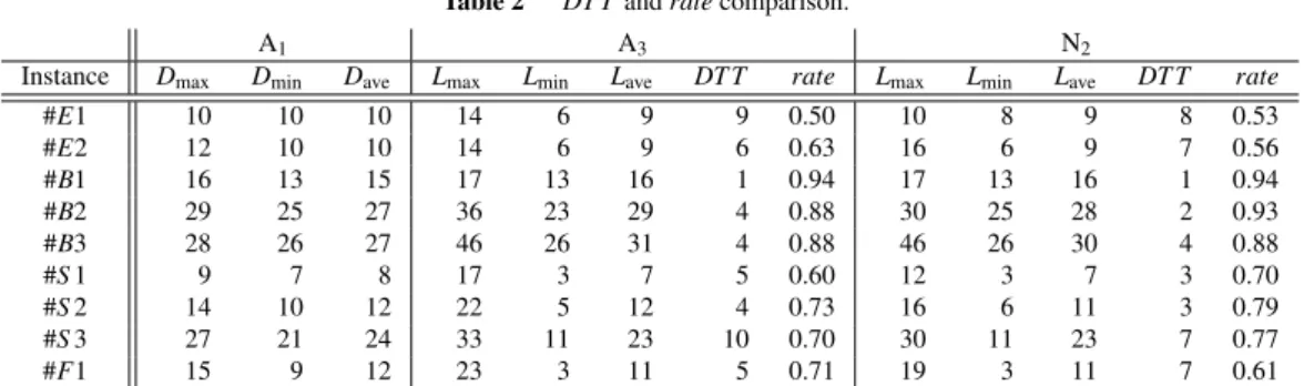
Table 2 DT Tandratecomparison.
A1 A3 N2
Instance Dmax Dmin Dave Lmax Lmin Lave DT T rate Lmax Lmin Lave DT T rate
#E1 10 10 10 14 6 9 9 0.50 10 8 9 8 0.53
#E2 12 10 10 14 6 9 6 0.63 16 6 9 7 0.56
#B1 16 13 15 17 13 16 1 0.94 17 13 16 1 0.94
#B2 29 25 27 36 23 29 4 0.88 30 25 28 2 0.93
#B3 28 26 27 46 26 31 4 0.88 46 26 30 4 0.88
#S1 9 7 8 17 3 7 5 0.60 12 3 7 3 0.70
#S2 14 10 12 22 5 12 4 0.73 16 6 11 3 0.79
#S3 27 21 24 33 11 23 10 0.70 30 11 23 7 0.77
#F1 15 9 12 23 3 11 5 0.71 19 3 11 7 0.61
Dmax,min,ave:max.,min.,avg.of the Manhattan distance of each target pin-pair Lmax,min,ave:max.,min.,avg.wire length
Fig. 6 Routing patters generated by our method.
to the Nakatani algorithm. On the other hand, in the point of view ofdmax, our method shows the ability to find length matching routing patterns that the Nakatani algorithm can- not find.
Figure 6 shows routing patterns generated by our algo- rithm for some instances. The location of source-pins and sink-pins are the same in each series, and the difference of instances in a series is the amount and location of obstacles.
5.2 Quality of Target Pin-Pair Set
The quality of the target pin-pair set is confirmed by how the target pin-pair set is similar to the connected pin-pairs in a routing pattern of the Nakatani algorithm. A routing pattern generated by the Nakatani algorithm step 2 (N2) is one of the good solutions that achieve the minimum total wire length and the small differences of each wire length. The similarity of the target pin-pair set and connected pin-pairs in N2 is measured by the metrics ofDT Tandrate.
DT T is the average Manhattan distance of sink-pins in the target pin-pair set and in a routing pattern whose source- pins are the same. If a target pin-pair is connected in a rout- ing pattern,DT T be 0.
Therateis a metric that represents how much the tar- get pin-pairs is connected in a routing pattern. The value is given byrate=Lave/(Lave+DT T).
An example of calculating DTT andrateis shown in the Fig. 7. Where the target pin-pairs are (A,X),(B,Y),(C,Z),
Fig. 7 DT Tandrate.
and the connected pin-pairs are (A,Y),(B,Z),(C,X).
TheDT T in this case is 2. Seeing the source-pinA,X is the target sink-pin and Y is the connected sink-pin, then the Manhattan distance of these sink-pins is 2. For B, the sink-pins areYandZ, then the Manhattan distance is 1. For C, the sink-pins areZandX, then the Manhattan distance is 3. TheDT T is an average of these Manhattan distances, so it is (2+1+3)/3=2.
Theratein this case is 0.65. The total wire length of this pattern is 11, and the average wire lengthLaveis 11/3= 3.7. Therateis calculated by Lave/(Lave+DT T), so it is 3.7/(3.7+2)=0.65.
TheDT T and theratefor benchmark instances are in the Table 2. The quality of the target pin-pair set is con- firmed by theDT T and theratein the column ofN2, which is a comparison with the Nakatani method step 2. The Man- hattan distance of selected target pin-pairs is concluded in the column ofA1, which is a result of our method step 1.
Theratefor B series and S series is over 0.7. Our tar- get pin-pair selection algorithm seems to perform well es- pecially for B series because, in the performance evaluation above, our method finds good length matching routing pat- terns.
For E series and F series, therateis about 0.5. Seeing the routing pattern Fig. 6, source-pins in E series and F se- ries are placed nearby each other and also include obstacles.
Since our pin-pair selection algorithm does not take obsta- cles or connectivity of pin-pairs into account, it is thought that our algorithm selects pin-pairs that cannot realize the connection of them as a target pin-pairs for these instances.
From this evaluation, our target pin-pair selection al- gorithm selects good pin-pairs as target pin-pairs for some cases. However, inappropriate pin-pairs might be selected for some other cases, so there are spaces to improve its per- formance.
5.3 Performance of Target Pin-Pair Connection Algorithm The performance of our target pin-pair connection algorithm is evaluated by how the target pin-pairs are connected in the routing pattern. Seeing theDT Tand therateof our method, the performance can be seen. The result of theDT Tand the rateis in theA3column of the Table 2.
In the cases of B1, B2, B3, S2, S3, and F1, therateis over 0.7. Therateof these cases inN2is also over 0.7. Then, we can see that our connection algorithm realizes the target pin-pair connection when appropriate pin-pairs are selected.
6. Conclusion
In this paper, we proposed a fast length matching routing method for the set-pair routing problem. In the set-pair rout- ing, although pin-pairs to be connected is flexible, it is ex- pected that combinations of pin-pairs which realize length matching are restricted. In our method, such a combination of pin-pairs is selected in advance, then routing is performed to realize the connection of the selected pin-pairs. Heavy iterative steps are not used for both the selection and the routing, then a routing pattern is generated in a short time.
In the experiments, we confirmed that the quality of routing patterns generated by our method is almost equivalent to the Nakatani algorithm. Furthermore, our method finds length matching routing patterns that the Nakatani algorithm can- not find. The computation time is about 360 times faster than the Nakatani algorithm.
References
[1] Y.-K. Ho and Y. Chang, “Multiple chip planning for chip-interposer codesign,” The 50th ACM/EDAC/IEEE Design Automation Confer- ence (DAC), pp.1–6, 2013.
[2] W. Liu, M.-S. Chang, and T. Wang, “Floorplanning and sig- nal assignment for silicon interposer-based 3D ICs,” The 51st ACM/EDAC/IEEE Design Automation Conference (DAC), pp.1–6, 2014.
[3] Y. Kohira, S. Suehiro, and A. Takahashi, “A fast longer path al- gorithm for routing grid with obstacles using biconnectivity based length upper bound,” IEICE Trans. Fundamentals, vol.E92-A, no.12, pp.2971–2978, Dec. 2009.
[4] Y. Kohira and A. Takahashi, “CAFE router: A fast connectivity aware multiple nets routing algorithm for routing grid with ob- stacles,” IEICE Trans. Fundamentals, vol.E93-A, no.12, pp.2380–
2388, Dec. 2010.
[5] Y. Takashima, A. Takahashi, and Y. Kajitani, “Routability of FPGAs with extremal switch-block structures,” IEICE Trans. Fundamentals, vol.E81-A, no.5, pp.850–856, May 1998.
[6] Y. Nakatani and A. Takahashi, “A length matching routing algorithm for set-pair routing problem,” IEICE Trans. Fundamentals, vol.E98- A, no.12, pp.2565–2571, Dec. 2015.
[7] K. Akagi, S. Sato, and A. Takahashi, “Target pin-pair selection algo- rithm using minimum maximum-edge-weight matching for set-pair routing,” The 21st Workshop on Synthesis And System Integration of Mixed Information Technologies (SASIMI 2018), pp.337–342, March 2018.
[8] K. Akagi, S. Sato, and A. Takahashi, “An idea for maximizing tar- get pin-pair connections in set-pair routing,” The 32nd International
Technical Conference on Circuits/Systems, Computers and Commu- nications (ITC-CSCC 2017), pp.62–65, July 2017.
[9] A. Itai, Y. Perl, and Y. Shiloach, “The complexity of finding maxi- mum disjoint paths with length constraints,” Networks, vol.12, no.3, pp.277–286, 1982.
[10] M.M. Ozdal and M.D.F. Wong, “Algorithmic study of single-layer bus routing for high-speed boards,” IEEE Trans. Comput.-Aided De- sign Integr. Circuits Syst., vol.25, no.3, pp.490–503, 2006.
[11] M.M. Ozdal and M.D.F. Wong, “Algorithmic study of single-layer bus routing for high-speed boards,” IEEE Trans. Comput.-Aided De- sign Integr. Circuits Syst., vol.25, no.3, pp.490–503, 2006.
[12] J. Edmonds and R.M. Karp, “Theoretical improvements in algorith- mic efficiency for network flow problems,” J. ACM (JACM), vol.19, no.2, pp.248–264, April 1972.
[13] E.W. Dijkstra, “A note on two problems in connexion with graphs,”
Numer. Math., vol.1, no.1, pp.269–271, 1959.
Shimpei Sato received the B.E., M.E., and D.E. degrees in engineering from Tokyo In- stitute of Technology, Tokyo, Japan, in 2007, 2009, and 2014, respectively. He is currently an Assistant Professor with the Department of In- formation and Communications Engineering of Tokyo Institute of Technology. From 2014 to 2016, he worked in High performance comput- ing area as a post doctoral researcher, where he investigated an application performance analy- sis/tuning method. His current research interests include approximate computing realization by architecture design and cir- cuit design and their applications. He is a member of IEEE and IPSJ.
Kano Akagi received the B.E. and M.E.
degrees in engineering from Tokyo Institute of Technology, Tokyo, Japan, in 2017 and 2019, respectively. Her current research interests in- clude VLSI layout design and combinational al- gorithms.
Atsushi Takahashi received the B.E., M.E., and D.E. degrees in electrical and electronic en- gineering from Tokyo Institute of Technology, Tokyo, Japan, in 1989, 1991, and 1996, respec- tively. He was at the Tokyo Institute of Tech- nology as a Research Associate from 1991 to 1997, and as an Associate Professor from 1997 to 2009 and from 2012 to 2015. From 2009 to 2012, he was at Osaka University, Suita, Japan, as an Associate Professor. He visited University of California, Los Angeles, U.S.A., as a Visiting Scholar from 2002 to 2003. He is currently a Professor with Department of Information and Communications Engineering, School of Engineering, Tokyo Institute of Technology. His current research interests include VLSI layout design and combinational algorithms. He is a senior member of IEEE and IPSJ, and a member of ACM.