System Using Fingerprint
Database Constructed with Estimated Reference Locations
Submitted to
Graduate School of Information Science and Technology, Hokkaido University
2020
Myat Hsu Aung
Recently, positioning systems have been widely used in consumer devices. The current position information of people and objects may help to navigate themselves to their destination in outdoor environment and even in indoor environment. Posi- tioning systems play an essential role not only in navigation and tacking but also in many location-based applications. Global positioning system (GPS) works well in outdoor environments. However, the indoor positioning systems still have the great challenge for such a platform because of signal blockage and attenuation and hence causing it large error in position and reduces the sensitivity below the threshold of GPS receivers.
Many researchers have developed indoor positioning systems using various tech- niques. A major difficulty in indoor localization systems is the trade-off between accuracy and their costs in terms of infrastructure deployment and calibration pro- cess. A system has higher performance also has higher cost. Indoor positioning systems need higher accuracy than outdoor positioning systems due to the relatively narrower spaces available in indoor environments. Depend on the applications, it requires the various accuracy. We investigate a Wi-Fi-based indoor positioning sys- tem. In our research work, we have been implemented a Wi-Fi-based indoor po- sitioning system using fingerprint method. The fingerprint database is constructed with estimated reference locations. We further propose the construction of finger- print database using two merging methods to improve the database management.
The proposed approach can control accuracy for any location-based applications.
Wi-Fi-based indoor positioning system is a positioning system that is used to
locate objects or devices using the information from the Wi-Fi access points. There
are several approaches to estimate positions such as trilateration or multilateration,
triangulation, and fingerprinting. In this thesis, implementations of Wi-Fi-based in-
door positioning system using fingerprint method are investigated. The fingerprint
method does not require installing additional hardware such as dedicated Wi-Fi de-
vices. In addition, the actual access point locations are not required. However, the site survey process is required to know the actual reference locations stored in the fingerprint database. This process requires quite a large cost since many data should be collected with their actual positions using precise indoor maps or floor plans.
Motivated by this, we propose a Wi-Fi-based indoor positioning system using es- timated reference locations. We are trying to develop a method to create reference location databases without precise reference locations. In our proposed approach, the database is constructed by gathering pairs of media access control (MAC) ad- dresses and received signal strength indicator (RSSI) values using a reference device moving at a constant speed with a simple direction. Assuming a constant speed, the location of each reference location can be estimated from the velocity. To estimate the user’s position, we propose a position estimation algorithm using Euclidean- like distance that finds the best match of the current RSSI values in the fingerprint database. Estimation accuracy evaluation results show that our proposed approach can estimate the user’s position without any precise reference locations.
In the fingerprint method, the database construction is important for position
estimation performance. We proposed a Wi-Fi-based indoor positioning system us-
ing a fingerprint method, whose database is constructed with estimated reference
locations. The reference locations and their information, called data sets, are ob-
tained by moving reference devices at a constant speed while gathering information
of available access points. Each data set includes some errors due to such as the
fluctuation of RSSI values, the device-specific Wi-Fi sensitivities, the access point
installations, and removals. To tackle this problem, we propose two methods to
merge data sets to construct a consistent database suppressing such undesired ef-
fects. One method is using the mean-shift clustering algorithm to get estimated
reference locations from multiple data sets. The number of estimated reference
locations in the database depends on the mean-shift parameter to calculate means
in the mean-shift algorithm. The experimental results show that the average error
can be reduced compared with the database construction using one data set as the
database. The other method assumes that the intervals of reference locations in the
database are constant and that the fingerprint for each reference location is calcu-
lated from multiple data sets. This constant interval is called a grid size, and the
number of estimated reference locations depends on the grid size. When merging
data sets using a grid size, RSSI values in a specific area are averaged so that it can
be expected to reduce noises due to the RSSI value fluctuation. The performance
can be controlled by changing the grid size depending on the applications. Through
locations. In the grid-based approach, the estimated position error reduces in cases
having a large number of reference locations. The obtained results show that the
grid-based approach is effective and performs comparatively better. We have cre-
ated the Wi-Fi-based indoor positioning system that is the cost effective and flexible
for any location-based application.
Acknowledgments
I would like to express my gratitude to my supervisor, associate professor Hiroshi Tsutsui, for the patient guidance, much encouragement, helpful advice, and essen- tial support for the success of my work provided throughout my research. I have learnt many things about research working from him, and how to manage risks and particularly how to explore new ideas. His guidance helped me in all the time of research.
I also thank professor Yoshikazu Miyanaga for his support and guidance though during my study program.
My sincerest gratitude also goes out professor Takeo Ohgane, professor Kuni- masa Saitoh, and associate professor Matteo Convertino for taking time to examine the contents of this thesis and providing valuable suggestions and comments that improved my research and dissertation as the members of my dissertation commit- tee.
I would like to thank the Scholarships by the ASEAN University Network/
Southeast Asia Engineering Education Development Network (AUN/SEED-Net) Project, JICA for giving me the opportunity to attend the doctoral degree course at Hokkaido University as a JICA scholarship student and providing financial assis- tance to conduct this research for three years.
I also thank the GI-CoRE GSB, Hokkaido University for fruitful discussions.
This work is supported in parts by the Ministry of Internal Affairs and Communi- cations for SCOPE Program (175003017).
During the four and a half years in which I have been doing my research, I am thankful to all the members of the Information and Communication Networks Laboratory for their help and accompany.
Finally yet importantly, I wish to thank my family for all the love and support,
during the year of my PhD study. Without their support and encouragement, my
dissertation would not have been possible.
Publications
Transactions
1. Ye Chan, Myat Hsu Aung, Pho Kaung, “Fuzzy Adaptive Fusion Filter for RSSI Siganl Processing in Indoor Navigation,” University of Yangon Research Journal, Vol. 9, No. 2, pp. 407–412, 2019.
2. Myat Hsu Aung, Hiroshi Tsutsui, Yoshikazu Miyanaga, “WiFi Fingerprint Based Indoor Positioning Systems Using Estimated Reference Locations,”
IEICE Transactions on Fundamentals of Electronics, Communications and Computer Sciences, Vol. E103-A, No. 12, Dec. 2020.
Conference Paper with Referee
1. Myat Hsu Aung, Hiroshi Tsutsui, Yoshikazu Miyanaga, “An accuracy evaluation of WiFi based indoor positioning system using estimated reference locations,” Proceedings of International Workshop on SmartInfo-Media Systems in Asia (SISA), pp. 321–326, Sept. 2017.
2. Myat Hsu Aung, Hiroshi Tsutsui, Yoshikazu Miyanaga, “Construction and
Management of Fingerprint Database with Estimated Reference Locations for
WiFi Indoor Positioning Systems,” Proceedings of the 23rd Multi-conference
on Systemics, Cybernetics and Informatics (WMSCI 2019), Vol. 2, pp. 7–10,
Jul. 2019.
1. Myat Hsu Aung, Hiroshi Tsutsui, Yoshikazu Miyanaga, “An Implementation of WiFi Based Indoor Positioning System Using Estimated Reference Locations,” Proceeding of GI-CoRE GSQ, GSB & IGM Joint Symposium, Jul. 2017.
2. Myat Hsu Aung, Hiroshi Tsutsui, Yoshikazu Miyanaga, “WiFi Indoor Positioning System Using Fingerprint Database Constructed by Mean-Shift Clustering with Estimated Reference Locations,” Proceedings of the GSB Student Workshop, The 2nd GI-CoRE GSQ, GSB & IGM Joint Symposium, Aug. 2018.
3. Myat Hsu Aung, Hiroshi Tsutsui, Yoshikazu Miyanaga, “An Accuracy
Evaluation of Fingerprint Database Constructed by Mean-Shift Clustering for
WiFi Indoor Positioning Systems,” Proceedings of 2018 Winter International
Symposium on Big-Data, Cybersecurity and IoT, Dec. 2018.
Contents
1 Introduction 1
2 Related works 6
2.1 Positioning system . . . . 6
2.1.1 Radio frequency based positioning system . . . . 7
2.1.2 Non-radio frequency based positioning system . . . . 11
2.2 Distance estimation methods . . . . 14
2.2.1 Time of arrival (ToA) . . . . 14
2.2.2 Time difference of arrival (TODA) . . . . 15
2.2.3 Angle of arrival (AOA) . . . . 16
2.2.4 Received signal strength indicator (RSSI) . . . . 16
2.3 Location estimation methods . . . . 18
2.3.1 Trilateration . . . . 18
2.3.2 Triangulation . . . . 19
2.3.3 Fingerprinting . . . . 19
2.4 Conclusion . . . . 20
3 Proposed Wi-Fi-based indoor positioning system using estimated refer- ence locations 24 3.1 Introduction . . . . 24
3.2 Proposed approach . . . . 25
3.2.1 Database construction . . . . 26
3.2.2 Position localization . . . . 27
3.3 Data collection . . . . 29
3.4 Experimental results . . . . 31
3.5 Conclusion . . . . 32
4 Database construction 42 4.1 Introduction . . . . 42 4.2 Related work . . . . 44 4.3 Proposed approaches . . . . 45
4.3.1 Proposed fingerprint database construction using mean-shift clustering . . . . 46 4.3.2 Proposed fingerprint database construction using grid size
and window size . . . . 47 4.4 Experimental results and discussion . . . . 49 4.5 Conclusion . . . . 58
5 Conclusion 63
List of Figures
2.1 Global positioning system. . . . 8
2.2 Wi-Fi-based positioning system. . . . 8
2.3 Simplified RFID system’s architecture. . . . 10
2.4 Principle of time of arrival (ToA). . . . . 14
2.5 Principle of time difference of arrival (TDoA). . . . 15
2.6 Principle of angle of arrival (AoA). . . . 16
2.7 Principle of Received signal strength indicator. . . . . 21
2.8 Positioning algorithms. . . . 21
2.9 The overview of trilateration algorithm. . . . 22
2.10 The overview of multilateration algorithm. . . . 22
3.1 The overview of the proposed system. . . . 26
3.2 Screen shot of the Android application. . . . . 28
3.3 Floor map and the forward direction in the experiment. Normalized position 0 corresponds to the starting point while 1 to the end point. The total distance is approximately 120 m. . . . 28
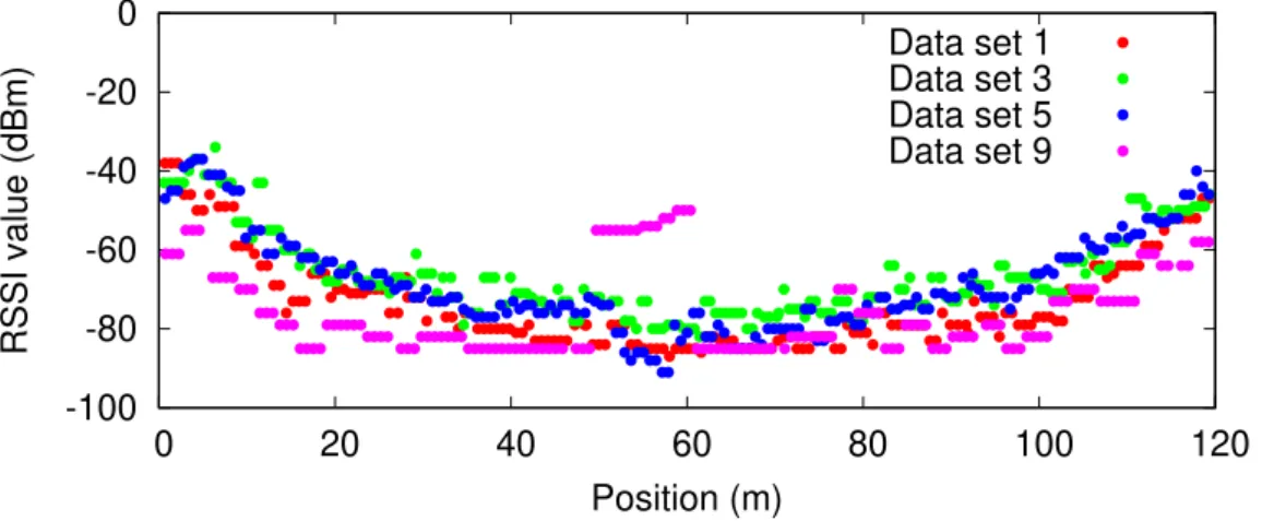
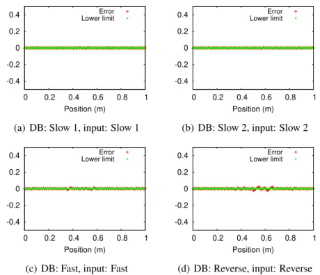
3.4 RSSI values of an AP (MAC address) in different data sets from different positions. The data set number is the same as in Table 4.1. 30 3.5 Normalized error of each estimated position using same data set for database creation and testing input data (Device (A)). . . . 34
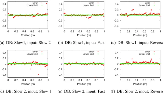
3.6 Normalized error of each estimated position using different data set for database creation and testing input data (Device (A)). . . . 34
3.7 Normalized error of each estimated position using same data set for database creation and testing input data (Device (B)). . . . 35
3.8 Normalized error of each estimated position using different data set
for database creation and testing input data (Device (B)). . . . 35
3.9 Normalized error of each estimated position using same data set for database creation and testing input data (Device (A), Day 2). . . . . 36 3.10 Normalized error of each estimated position using different data set
for database creation and testing input data (Device (A), Day 2). . . 36 3.11 Normalized error of each estimated position using same data set for
database creation and testing input data (Device (B), Day 2). . . . . 37 3.12 Normalized error of each estimated position using different data set
for database creation and testing input data (Device (B), Day 2). . . 37 3.13 Normalized error of each estimated position (Different device data
in same day (Day 1)). . . . . 38 3.14 Normalized error of each estimated position (Different device data
in same day (Day 2)). . . . . 39 3.15 Normalized error of each estimated position (same device data in
different day (Device A)). . . . . 40 3.16 Normalized error of each estimated position (same device data in
different day (Device B)). . . . . 41 4.1 Overview of the proposed system. . . . 45 4.2 Relationship between reference points, grid size d, and a window
whose size is w. . . . 48 4.3 Normalized error of each estimated position. Cond. B and input
data set 2 are used. . . . 52 4.4 Normalized error of each estimated position. Cond. B and input
data set 2 are used. . . . 52 4.5 Normalized error of each estimated position. Cond. B and input
data set 2 are used. . . . 53 4.6 Normalized error of each estimated position. Cond. B and input
data set 2 are used. . . . 53 4.7 Normalized error of each estimated position. Cond. A and input
data set 1 are used. The window size is given by w = d. . . . . 54 4.8 Normalized error of each estimated position. Cond. A and input
data set 1 are used. The window size is given by w = d. . . . . 54 4.9 Normalized error of each estimated position. Cond. A and input
data set 1 are used. The window size is given by w = d. . . . . 55 4.10 Normalized error of each estimated position. Cond. A and input
data set 1 are used. The window size is given by w = d. . . . . 55
List of Figures List of Figures
4.13 Error distribution of estimated position for each database creation. . 61
2.1 Comparison of indoor positioning technologies. . . . 23 3.1 Reference Android devices. . . . 29 3.2 Different types of data set depends on the moving speed and direc-
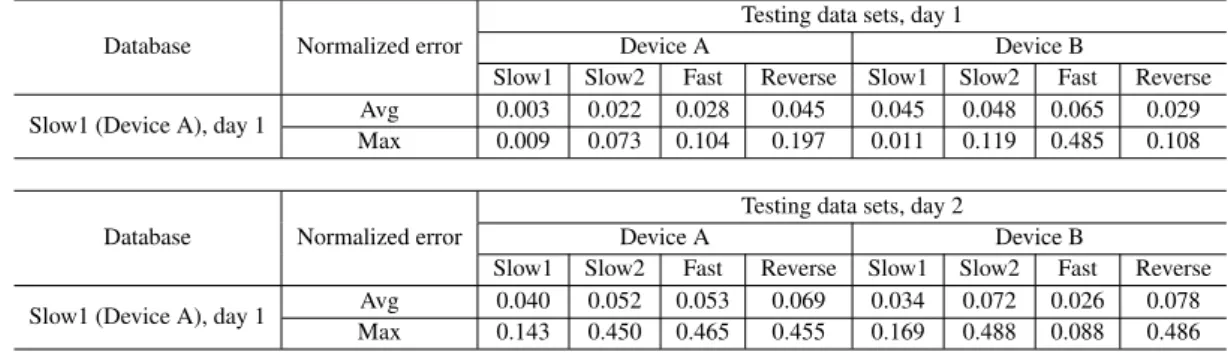
tion . . . . 29 3.3 Number of samples for each data set. . . . 29 3.4 Evaluation results of database creation (Slow 1, Device A, Day 1)
using for different testing data sets. . . . 33
4.1 Data sets for the fingerprint database construction. . . . 49
Introduction
Positioning system is a system which provides the position information of objects or people. This system uses to navigate and track objects or people in outdoor en- vironment and even in indoor environment. In ancient times, people used celestial elements such as sun, moon, and star to known the current location, and the way and direction for navigate themselves to their destination. They known their loca- tion based on natural landmarks, such as trees, mountains, and rivers. However, sometimes they lost their way when they cannot see sun, moon, and star. Later, people used tools like hourglass, map, compass, and among others for navigation.
Drawing details landmarks, they kept and recorded the location information on the map. Using tools, the more accurate navigation can be achieved.
In the 18th century, the object can be detected and estimated the distance be- tween two ships using radio wave. During the World War II, the radar technology was developed using radio wave. Radar provides the range of the object from the radar device by reflected radio signal from the object. That can be known the loca- tion of the object from the radar device.
In the 19th century, the first satellite was lunched. The global positioning sys- tem (GPS) was developed which used satellites. GPS was originally proposed for military service to navigate ship, aircraft, and automobile. The location of vehicles can be estimated using radio signal from at least three or more satellites by GPS receiver. The technology has been allowed for civilian use from the 1980s. The technology is rapidly developed and GPS receivers are installed and build in many devices like smartphones and mobile devices. The location of the objects or people is easy to known and more accurate for navigation and tracking systems.
Nowadays positioning systems have become indispensable not only for navi-
Chapter 1. Introduction
gation and tracking but also for various location-based applications such as health care system, security, manufacturing and location-based IoT system. For such ap- plications, different level of accuracy is desired that depends on each application requirements. The global positioning system (GPS) is most popular and suitable technology for outdoor positioning system. However, the large error occurs in in- door environment because the GPS signal becomes weak when they penetrate the construction materials. Reliable and accuracy of indoor positioning system remains as one of the greatest challenges in the area of location-based application. Also, a flexible and low-cost indoor positioning system is highly demanded. There are mul- tiple factors that have direct impact on the development of indoor positioning solu- tions such as environment, accuracy, application, and suitable technologies, among many others.
The indoor positioning systems (IPS) in public buildings such as shopping malls, stations, and airports is quite attractive not only for the general users but also the location-aware service providers. In case of buildings for specific users such as company buildings, universities, and schools, the IPS will help us to develop more efficient navigation systems and people tracking systems. For indoor positioning systems (IPS), RF signals from wireless devices such as Wi-Fi, Bluetooth, ultra- wide band (UWB), and radio frequency identification (RFID) devices can be uti- lized to estimate mobile device positions. The other type is non-RF based system that includes infrared, visible light communication, sound-based, vision-based, and inertial sensor. In Chapter 2, we review some existing indoor positioning systems and their positioning technologies. In Sect. 2.1, we briefly introduce radio frequency (RF) based positioning systems and non-RF based positioning systems. The advan- tages and disadvantages are presented for each system.
We focus on the most cost-effective method that is Wi-Fi-based IPS since the Wi-Fi coverage is getting higher due to the significantly increasing number of pri- vate or public Wi-Fi access points (APs) in metropolitan areas. Wi-Fi has been a de- fault feature in most of the current smartphones, laptops and other portable devices.
However, existing Wi-Fi network is originally developed for data communication
rather than positioning purposes. The positioning techniques are required to use in
positioning system using Wi-Fi network. The distance between the Wi-Fi access
point and user’s mobile device can be estimated using measurement signal such as
received signal strength indicator (RSS), time of arrival (TOA), time difference of
arrival (TDOA), and angle of arrival (AOA) from the access point. In Sect. 2.2,
we present the principle of such distance measurement techniques. The location
of user’s mobile device can be estimated using the distance measurement between the access points and user’s mobile device with some positioning methods such as trilateration, triangulation, and fingerprint which are described details in Sect. 2.3.
In this research, we focus on the fingerprinting approach since this approach does not require additional hardware installation such as dedicated beacon devices.
The actual location of each access point does not required. The user positions are estimated by finding the best match of the current information of available APs in fingerprint database.
There are various research works in literature proposing Wi-Fi-based IPS with different approaches in fingerprint database creation and location estimation. In the traditional fingerprint method, the site survey process is required to know the actual reference locations in the coverage area. We need to store the information of APs reachable from a lot of known reference locations. Most of the research works are using the previously determined reference locations during their fingerprint database constructions. While there are many efforts to know the actual position of reference locations in a large area, this site survey process is time-consuming, labor-intensive, and vulnerable to environmental changes. Focusing on the diffi- culty of database creation, we are trying to develop a method to create the database of reference location information which does not require precise reference locations.
In Chapter 3, we proposed a Wi-Fi-based indoor positioning system using a fingerprint method, whose database is constructed with estimated reference loca- tions. We created the fingerprint database by gathering pairs of media access con- trol (MAC) addresses and received signal strength indicator (RSSI) at each estimate reference location using a reference device moving in a constant speed with sim- ple direction. It can be estimated the location of each reference location. Pair of MAC address and RSSI values from all available APs from each estimated refer- ence location is stored in fingerprint database. To estimate the user’s location, we implemented the position estimation algorithm to find the best matching reference location which stored in the fingerprint database. In the position estimation al- gorithm, we used Euclidean-like distance to calculate the vector distance between user’s location and reference locations. According to evaluation results, the user’s location can be estimated without any precise reference locations. It reduce the administration cost to know the actual reference locations.
However, the accuracy is influenced by the number of reference locations stored
in the database and the device-specific Wi-Fi sensitivity. When we use dense ref-
erence locations to achieve high resolution, the amount of data stored in database
Chapter 1. Introduction
increases. In this case, a high computational cost is required in the user’s position estimation process. The fingerprint database is established using received signal strength indicator (RSSI) values from APs, with the mobile device scanning for RSSI values from all available APs. In a dense AP environment, not all APs may be observed in a single sampling time. In these instances, when the mobile device is unable to receive RSSI values from some APs, these values are classified as unavail- able RSSI values. Furthermore, RSSI values fluctuate due to spatial and temporal variations of interference, hardware variations, environmental effects such as human presences, and resource collision caused by other devices utilizing the same service at the same time. This leads to an inaccurate estimation of the user’s location by se- lecting an irrelevant reference location from the database. Another difficulty is that the database depends on the APs, which means new installations and replacements of APs have a significant impact on the estimation accuracy. Considering these is- sues, not only the database creation but also how to manage the database after the database creation is essential. It might be also possible that the user’s input data is used for update the fingerprint data on the fly, utilizing the user’s locality.
To mitigate the challenges caused by the fluctuation of RSSI values, multiple data sets are used to create a single database with higher fidelity. The multiple data sets are collected using different device and different time duration to considering the device sensitivity and APs installations and replacements. In Chapter 4, we cre- ated the fingerprint database with estimated reference locations from multiple data sets using two data merging methods such as the mean-shift clustering algorithm and data merging with constant interval. Using mean-shift clustering algorithm, the number of estimated reference locations depends on the thresholds parameter, a radius for the mean calculation to settle each reference location as the result of clustering. The large mean-shift parameter gives high computation time in each ref- erence location calculation compare with small parameter. However, the large error occurs in the large mean-shift parameter. This proposed approach can be reduced the accuracy error due to the estimation accuracy evaluation results that compared with the database are constructed using one data set. Using this approach, the loca- tion of each reference locations in database is changed whenever updating database.
The second merging method involved the constant interval between the refer-
ence location using the grid size. The number of reference location in merged data
set from multiple data sets depends on the grid size. When merging data sets, RSSI
values are averaged in the window of each estimated reference location in the new
data set to be stored in the fingerprint database. We showed the effectiveness of the
proposed approach through the experimental results, including the errors and accu- racy for various grid sizes and window sizes. The large grid sizes give high accuracy but large error while the small grid sizes give a low error but low accuracy. This means that, in the proposed merging method, the performance can be controlled, changing the grid size depending on applications. Note that the window size w can be properly set for each grid size d regarding the experimental result. When d is small, a normalized average error of 0.02 corresponding 2.4 m can be archived.
Also, when d is large, an accuracy of 80 % can be archived. Comparison of two
merging method, updating and maintaining the fingerprint database require high
computation cost using mean-shift clustering algorithm, although the mean-shift
clustering algorithm is popular in data clustering. Finally, Chapter 5 summarizes
and concludes this thesis.
Chapter 2
Related works
2.1 Positioning system
Positioning systems have become indispensable not only for navigation and track- ing but also for various location-based applications. There are numbers of existing positioning systems which utilize a variety of sensing technologies and system ar- chitectures. These systems have varying characteristics, such as accuracy, scalabil- ity, cost, and technology. This chapter describes some positioning systems and their principles.
There are two main types of positioning technologies: radio frequency (RF) based system which used radio signal from transmitter device to know the distance from the receiver devices, and non-RF based system which utilized the different signals such as laser, light, acoustic signal, magnetic, and among others. RF based systems are such as Global positioning system (GPS) based, Wi-Fi-based, ultra- wide band based, radio frequency identification (RFID) based, and Bluetooth-based.
The other type includes infrared-based, visible light based, sound-based, vision- based, and inertial sensor. In Sect. 2.1.1 and Sect. 2.1.2, we discuss their benefits and limitations in the positioning system, and review related existing positioning systems.
These technologies are used in position system that depend on the requirements
of applications and environments. Among them, GPS system, Wi-Fi based position-
ing system, and inertial positioning system are used due to their specific character-
istics. Wi-Fi coverage is getting higher due to the significantly increasing number
of private or public Wi-Fi access points (APs) in metropolitan areas. GPS receiver
and some inertial sensor have been built in most of the current some vehicles, smart- phones, laptops and other portable devices.
In Sect. 2.2, we introduce four typical distance measurements, namely time of arrival (TOA), time difference of arrival (TDOA), angle of arrival (AOA), and re- ceived signal strength (RSS), utilize to estimated distance from the transmitter to receiver. Using the measurement signal, the position of the user’s device can be calculated using positioning algorithm. There are various positioning algorithms such as trilateration, triangulation, and fingerprinting that describe in Sect. 2.3. We present comparison of positioning algorithms with different measurement in each positioning system.
2.1.1 Radio frequency based positioning system
Global positioning system (GPS) based
The global positioning system (GPS) is a satellite-based radio positioning system with a nominal constellation of 24 satellites. It was originally intended for mili- tary navigation applications, later the system was made available for civilian use.
GPS has been widely used for navigation and positioning, and various types of GPS receivers for different positioning accuracy have been available. In the gen- eral GPS, as shown in Fig. 2.1, GPS receiver needs to receive GPS signals from a least three satellites to employ a position calculation process to determine physical locations [1]. Using signals from four or more satellites, 3D position of user can be determined.
GPS is most popular and suitable technology for outdoor positioning system.
Since GPS is a satellite based positioning system, it works well in outdoor environ- ment but not well in indoors navigation. The large error occurs in indoor environ- ment because the GPS signal becomes weak when they penetrate the construction materials. Indoor positioning systems need higher accuracy than outdoor localiza- tion systems due to the relatively narrower spaces available in indoor environments.
For indoor environment, it is required additional devices installation like GPS
repeater [2–4]. In [3], positioning accuracy about 2–4 m is achieved using GPS
repeater in indoor experiments. However, it is required to have infrastructure set-up
which could amount to large initial deployment costs.
2.1. Positioning system Chapter 2. Related works
Figure 2.1: Global positioning system.
Server
Return the estimated location Send data
(WAPs fingerprint)
Figure 2.2: Wi-Fi-based positioning system.
Wi-Fi-based
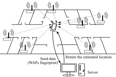
Wi-Fi is a technology that uses radio waves to connect to internet and communicate in local area network. Wi-Fi-based positioning system is used to determine the location of objects or devices using the information from the Wi-Fi access points.
There are several positioning techniques that use Wi-Fi-based positioning system.
Trilateration and triangulation techniques are used to know the position of user’s device by the device’s distance from access points. The distance between the Wi-Fi access points and user’s device can be calculated according to TOA, TDOA, AOA, and RSS which present in Sect. 2.2. Another position techniques is fingerprinting that is the most cost-effective method since Wi-Fi coverage is getting wider due to the significantly increasing number of private and public Wi-Fi access points (APs) in the metropolitan area. The existing Wi-Fi access points can be used in positioning system without installation additional devices.
There are two different methods for implementing user’s position computation process: self and remote positioning. In case of self positioning, the position is known by the user and the whole process operating on the user’s device. In remote positioning, the position is determined at the server side using the information of access points which are collected from the user’s device. The second method is typically used. In general Wi-Fi-based positioning systems, as shown in Fig. 2.2, a user sends data of access points reachable from the current position to the server, and receives the estimated user location information. There are various research works in literature proposing Wi-Fi-based IPS with different approaches in [5–13]. The accuracy of the Wi-Fi-based positioning systems varies from sub-meter to several meters for different algorithms and deployment densities.
Radio frequency identification (RFID) based
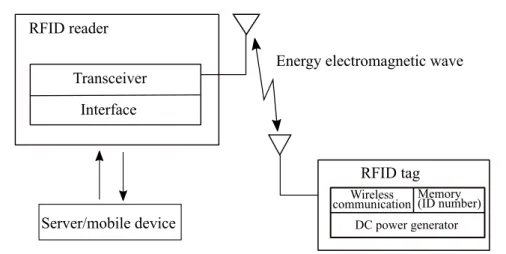
RFID is an automatic identification method that relies on storing and remotely re- trieving data using data-carrying devices known as RFID tags or transponders. The power required to operate device is transferred using a contactless technology from a data-capturing device and RFID reader. The basic communication between the reader and the transponder of an RFID system is based on radio frequency (RF) technology. The distance to be covered can be adjusted by using the frequency. An RFID reader generally acts as sender as well as receiver. It captures an encoded radio signal to interrogate the tag.
The RFID tags are primarily classified into active and passive tags. An active
2.1. Positioning system Chapter 2. Related works
Energy electromagnetic wave Transceiver
Interface RFID reader
RFID tag
Wireless
communication Memory (ID number) DC power generator
Server/mobile device
Figure 2.3: Simplified RFID system’s architecture.
tag is a battery-powered transceiver and thus has a wider transmission range, hence reducing the number of tags required for an installation. A passive tag has a shorter transmission range because it does not use a battery; it gets its power from reader’s signal before it can respond with information. The reader and tag, as well as a sever for position computation, are used in an RFID-based positioning system.
RFID positioning system can be classified as fixed-tag position and fixed reader or antenna position, in accordance with different roles of tags and readers/antennas.
In the fixed-tag, the tags are deployed on fix position while the readers/antennas are usually attached to mobile objects. This is cost effective when the objects to be tracked are relatively large, few in numbers, and usually move in a 2D plane or on a certain route. In the fixed reader/antenna scheme, the readers/antennas and tags are placed in an opposite way to the fixed-tag. The readers/antennas are installed at fixed positions while the tags are attached to the items to be tracked. Many equipment are need for this positioning system. RFID positioning system is better than GPS positioning system for both indoor and outdoor environment. But the cost of the whole system is high [14, 15].
Ultra-wide band based
Ultra-wide band (UWB) is a short-range high-speed radio technology for wireless
communication with the ability to have a robust resistance to non-line of sight and
multi-path effects. UWB can be used for positioning by utilizing the distance mea-
surement of the signals to obtain the distance between the UWB transmitters and
receivers which is called active UWB-based positioning. We can classified into two UWB-based positioning system: active and passive. Passive UWB-based po- sitioning system is a system that uses signal reflection, and not an attached UWB tag, to determine the position of a person or object by means of the principle of radar. When a person moves within a room with known positions of installed UWB transmitters and receivers, the body of the person reflects the signals emitted by the transmitters. The receivers sense the reflected signal, and the position of the person is estimated. The advantages of UWB-based indoor positioning system are long battery life for UWB tags, robust flexibility, high data rate, high penetrating power, low-power consumption and transmission, food positioning accuracy and perfor- mance, and multi-path effects. However, UWB is expensive to scale because of the need to deploy more sensors in a wide coverage area to improve performance. [16]
Bluetooth-based
Bluetooth is a short-range and low power technology that is used for peer to peer data communication. Bluetooth based positioning system is a system that locate and track objects and people inside a building by providing real-time position in- formation of user’s device using fixed Bluetooth sensors. Bluetooth devices that are within the range of the installed Bluetooth sensors are able to connect the user’s device, thus receiving information from the Bluetooth sensors. The position of the device are computed using different positioning techniques such as ToA, AoA, and RSSI [17, 18]. Bluetooth based system mostly uses RSSI due to less complex. Blue- tooth based positioning system is low cost and energy-efficient system. However, the many Bluetooth sensors are needed to install on a large scale due to short-range.
2.1.2 Non-radio frequency based positioning system
Infrared based
The system uses infrared signals to determine the position of object or people. Each location in a building covered with a network of IR sensors which detect these transmissions. IR can be used in two different ways; direct IR and diffuse IR.
The direct IR uses a point-to-point ad-hoc data transmission standard designed for
very low power communication. The diffuse IR has stronger signals than direct
IR. Direct IR requires line of sight between devices. However, diffuse IR does not
2.1. Positioning system Chapter 2. Related works
require direct line of sight due to wide angle LEDs which emit signals in many directions. Angle of arrival (AoA) is mostly used in IR-based positioning system.
Sound-based
There are two types of sound-based positioning system: acoustic signal and ultra- sound. The acoustic signal-based positioning system uses sound sources (audio speaker) from acoustic signals to estimate the user position by capturing the micro- phone sensors. The traditional method used for acoustic-based localization has been the transmission of modulated acoustic signals, containing time stamps or other time related information, which are used by the microphone sensors for TOA estimation.
The ultrasound based system uses ultrasonic sensor. The ultrasound based po- sitioning system also mainly relies on the TOA measurements of ultrasound signal and the sound velocity to calculate the distance between a transmitter and a receiver.
Ultrasonic positioning system has a more limited range because of the loss of en- ergy with the distance traveled. Also they are sensitive to ultrasonic ambient noise and have a low update rate.
The sound-based systems achieve high localization accuracy at room level. How- ever, they need high cost implementation. The sound-based systems need of extra infrastructure such as sound sources or ultrasonic sensors, those are expensive to deploy and maintain. The system implementation on a large scale is the disadvan- tages in this system. It make the sound-based not a very popular technology for positioning system in large sale area. However, nowadays the acoustic signal based becomes popular in indoor positioning system using existing sound sources in the building [19]. But the main disadvantage is the line of sight.
Vision-based
The vision-based positioning system is a system that determines the position of
a person or an object by identifying a image that in with view, with camera and
computer version based technology. The vision-based system uses camera’s motion
relative to a rigid scene to estimate the current position of the camera and to locate
moving objects or people in the images [20–22]. This system is very effective in
actual environment and low cost positioning system due to using low cost CMOS
sensors. However, incorrect recognizing the object of interest in the input image
leads to wroth positioning system.
Visible light communication based
Visible light communication (VLC) is an emerging technology for high-speed data transfer that used visible light, modulated and emitted primarily by light-emitting diodes (LEDs). Visible light communication (VLC) based positioning system uses light sensors to measure the position and direction of the LED emitters for tracking and navigation purposes. The LEDs transmit the signal, which when collected by receiver can be used for localization. The visible light communication is a short- range free-space optical wireless communication technology that uses visible light to transmit data at 380–780 nm of wavelength. In VLC based system, it consists of a light source, image sensor, and a line of sight communication channel. Light sources are mounted on the ceiling of a room to transmit signals from their known position. The signals are received and demodulated by image sensor from an un- known position. The position of image sensor is then calculated using this infor- mation. For visible light, AoA is considered the most accurate localization tech- nique. The advantage of visible light based localization is its wide scale prolifera- tion. However, a fundamental limitation is that line of sight between the LED and the sensors is required for accurate localization.
VL positioning system is complex in design, especially when implemented over a wide coverage area. However, the use of LEDs for landscape architecture or illu- mination has attracted attention, and the LED industry is rapidly growing as LEDs have several advantages such as long life expectancy, high tolerance to humidity, low power consumption, and environmental friendliness. Therefore, we can expect that the existing fluorescent lamps will be replaced with LED lights in the indoor environment. Using existing LED lights, the indoor positioning systems based on LEDs have been proposed [23].
IMU sensor based
Inertial measurement units (IMU) sensors based positioning system is system that
measures the position, orientation, and velocity of the user’s device using accelerom-
eter (motion sensor) and gyroscopes (rotation sensors) for tracking and navigation,
also known as an inertial navigation system (INS). In general, an inertial navigation
system (INS) is used with the dead reckoning method using IMU sensors. A start-
ing position of device is required. Since the sensors can only detect changes from
one state to another, the starting position has to be set and known for tracking and
navigation. Output of accelerometer and gyroscope measurements are 3D vectors
2.2. Distance estimation methods Chapter 2. Related works
Transmitter Receiver
d
Synchronized
Figure 2.4: Principle of time of arrival (ToA).
of accelerations and angular velocities that are used to derive a positioning solution.
This positioning solution includes the position (normally latitude, longitude), the direction (east, west, north, south), and the orientation (pitch, yaw, roll) [24]. To estimate device’s position and orientation, double integration of acceleration mea- surement and single integration of angular velocity are required. Use of integration is the main cause for position error of INSs because of accumulation of constant errors (sensor drift, bad sensor calibration, etc.). Due to the integration a constant error results in error in position of the device. For positioning system, INS combines with other positioning techniques have been developed [25–29].
2.2 Distance estimation methods
2.2.1 Time of arrival (ToA)
Time of arrival (ToA) is the ranging based distance measurement method that is the time taken for electromagnetic wave to travel the distance. The transmitter transmits a signal at a time that is known to the receiver. The receiver’s clock is somehow synchronized to the transmitter’s clock as shown in Fig. 2.4. The distance between the transmitter and receiver can be calculated using
d = (t
a− t
s) × c, (2.1)
where t
ais time of arrival and t
stime take-of from the transmitter. c is the speed of light. TOA is sometimes called time of flight (TOF). Knowing the distance from transmitters, the location of the receiver can be calculated.
TOA requires strict synchronization between transmitters and receivers and times- tamps to be transmitted with the signal. The delay time can be occurred the error.
The clock errors are usually less than 1 ms and varies slowly over time. In electro-
magnetic, time synchronization error is 0.3 m. In multipath indoor environments,
Transmitter 1
Receiver
d2 Not synchronized
Transmitter 2 Synchronized
d1
Figure 2.5: Principle of time difference of arrival (TDoA).
the obstacles deflect the emitted signals when the direct line of sight path between the transmitter and receiver is not available. Due to this effect, the location errors cannot be eliminated. The short time signal is better the performance, however, the noise can be occurred due to small signal power [30–33].
The satellite has very accurate rubidium clocks. These clocks are allowed to run freely in each satellite as it is difficult to synchronize 20 odd satellites. A quadratic polynomial expression is used to determine the correction to GPS Time. The pa- rameters of correction are determined by the master control station and uploaded to the satellites. With the correction, the GPS time obtained from the SV time is accurate to about 3 ns. The error contribution from this source can be 1 m.
2.2.2 Time difference of arrival (TODA)
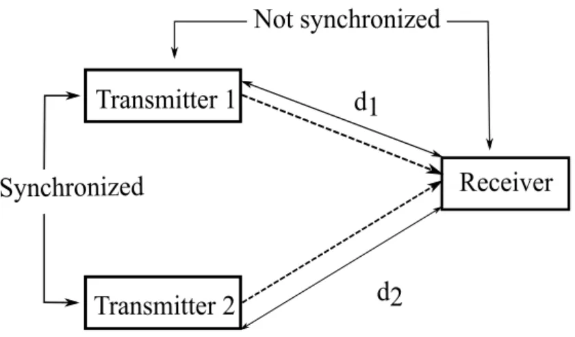
Time difference of arrival (TDOA) is also ranging-based distance measurement method. It also uses the time taken for signal to travel the distance between transmit- ter and receiver. However, TDOA is used to determine position of receiver based on the signal arrival time difference from multiple transmitters which are known the actual location. The principle of time difference of arrival is shown in Fig. 2.5.
Using the signal from multiple transmitters, a difference in distances between two transmitters can be calculated by multiplying the speed of light c and a difference in the arrival time from two transmitters as follows,
d
2− d
1= (t
r2− t
r1) × c. (2.2)
2.2. Distance estimation methods Chapter 2. Related works
Transmitter
Receiver 2
Receiver 1 θ
1θ
2Figure 2.6: Principle of angle of arrival (AoA).
There are two different architectures that is active and passive system. In both architectures, there is a need for synchronization. The active system needs one transmitter and multiple receivers. The synchronization is required between re- ceivers. In the passive system, there is one receiver and multiple transmitters. In case of GPS, there is the passive system. All the transmitters are synchronized closely. Some of the indoor locations [34–39], utilizes multiple receivers and single transmitter architecture.
2.2.3 Angle of arrival (AOA)
Angle of arrival (AOA) is the angle and distance calculated relative to two or mul- tiple receivers through the intersection of direction lines between the receivers. The calculation of the angle and distance is used to estimate and determine the position of a transmitter, and the information is used for tracking or for navigation pur- posed [40, 41]. Figure 2.6 shows the principle of angle of arrival (AoA). AoA had been achieved high average accuracy when the environment is line of sight.
2.2.4 Received signal strength indicator (RSSI)
Received signal strength indicator (RSSI) is a measurement of the power present in a
radio infrastructure, measured in decibel-milliwatts (dBm) or milliWatts (mW). As
all electromagnetic waves have inverse-square relationship between received power
and distance as in following expression, P
r∝ 1
d
2, (2.3)
where P
ris the received power at a distance d from transmitter.
Figure 2.7 shows the principle of RSSI values that related with distance between access point and mobile device. The RSSI values decrease as the signal propagates when the mobile device is apart from the access point. Using RSSI values and the signal propagation model along the line of sight, the distance can be calculated using following equation:
RSSI = −10n log
10d + A. (2.4)
Where n is the propagation path loss exponent, d is the distance between access point and mobile device, and A is the RSSI value at one meter of distance from access point as reference RSSI value of access point. In other to determine the path loss exponent, the RSSI values within 10 m of the sink will be measured with a step size of 1 m and the root mean square (RMS) of the measured RSSI values will be calculated and then the best value for the path loss exponent n.
The path loss exponent is a significant factor which depends on the local envi- ronment and differs from channel to channel. Typical path loss exponents (PLE) are different for various environments. In the buildings, the PLE’s range is 1.6 to 3.5 when the receiver and transmitter at the same floor, for multiple floors the PLE are between 2 and 6. However, attenuation due to obstacles in buildings expand the range of empirical PLE.
RSSI method is among the cheapest and easiest method to implement. However, it does not provide the best accuracy because of RSSI fluctuation. RSSI values fluctuate with various effect as follows:
1) Hardware: Orientation, direction, and type of antenna, and the device specific Wi-Fi sensitivity
2) Spatial: Distance between receiver (mobile device) and transmitter (access point) 3) Temporal: Time and period of measurement
4) Interference: resource collision caused by other devices utilizing the same ser-
vice at the same time
2.3. Location estimation methods Chapter 2. Related works
5) Human: User’s presence or absence, orientation, movement 6) Environment: Building types, materials
Using RSSI values in positioning system, filtering process is required to improve location accuracy. Various algorithms can be used to smooth the RSSI value and reduce error [42–44].
2.3 Location estimation methods
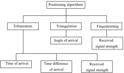
The location estimation methods specify how to calculate the position of objects and people. By knowing the distance to the transmitters using the distance estima- tion methods as mentions in Sect. 2.2, the location of objects and people can be estimated using location estimation methods such as trilateration, triangulation and fingerprint as shown in Fig. 2.8.
2.3.1 Trilateration
Trilateration is location estimation method which uses distance measurements rela- tive to known position to determine the position of the object. At least three known position of transmitters are required to use trilateration method. Similarly, four or more known position is used to determine the position of unknown device which is called multilateration. Figures 2.9 and 2.10 show the overview of trilateration and multilateration algorithm, respectively. The location of the target unknown receiver is computed as the intersection point of the spheres center at each transmitter and with radius equal to the distance to the receiver. The distance from each transmitter to receiver is described as following equation:
(x
i− x
u)
2+ (y
i− y
u)
2+ (z
i− z
u)
2= d
2i(2.5) where (x
i, y
i, z
i) and (x
u, y
u, z
u) are the known position of transmitter i = 1, 2, . . . , N , and the target unknown position, respectively. d
iis the distance between target and known position i. The distance between transmitter and receiver is calculated using TOA, TDOA, and RSSI. The position of receiver is estimated using trilateration algorithm with least square method.
Trilateration has been widely used in GPS positioning. GPS receivers use the
trilateration method to determine the user’s position, motion and direction. In in-
door positioning using Wi-Fi, bluetooth and other sensing devices, the additional
devices installation is required. The location of those devices is needed to know for distance calculation.
2.3.2 Triangulation
Triangulation uses the geometric properties of triangles to estimate the position of a target object by computing angular measurements relative to two known reference points. In other hand, the position of the target object is found by the intersection of two pairs of angle direction lines, a method known as direction finding. Angle of arrival is used to compute the distance between direction lines or fixed points to locate the object. The position of the object is determined by calculating the position of transmitter based on the angle and distance relative to the reference points. Furthermore, when two or three reference points are used to determine position, it results in a simple and low-cost system.
2.3.3 Fingerprinting
Fingerprint method has been used for indoor positioning system to estimate the position of objects by finding the best match of the current information of unknown position in an fingerprint database. The fingerprint method consists of two phases:
offline phase and online phase. In the offline phase, information from sensor or radio wave transmitter are collected at each specific location. Such locations are called reference locations. The collected data for each reference location is stored in a fingerprint database. This phase can be regarded as a database creation phase or training phase. In the online phase, the real-time position of the user is estimated using input set of current data that is collected by user’s mobile device. A feature vector called fingerprint is generated from the current data and it is compared with those stored in the fingerprint database. The position is estimated based on the best matching vector in the database.
In fingerprint method, the site survey process is required to known the actual location of reference locations in the coverage ares. There are many efforts to know the actual position of reference locations in a large area, this site survey process is time-consuming, labor intensive, and vulnerable to environmental changes.
Compared with other techniques like trilatration and triangulation, this tech-
nique is more suitable for positioning system in indoor environment which is use
existing infrastructure like Wi-Fi. Much research interest in Wi-Fi based indoor
2.4. Conclusion Chapter 2. Related works
positioning system using fingerprint method has developed focusing on various as- pects [43, 45–49].
2.4 Conclusion
The advantages and disadvantages of aforementioned various positioning system used in indoor environment are compared in Table 2.1. There are needed to con- sider not only accuracy and performance but also installation costs, calibration time, power consumption, maintenance and life time [50–53]. The cost of IPS contains several parts: the cost of the infrastructure components, system installation and maintenance. In case of GPS, it does not suitable for indoor environment due to the additional devices installation that leads to high cost and complex implementation.
The accuracy of RFID and IR based positioning systems are higher than other po- sitioning systems. However, the cost of the whole system is increased because of these extra infrastructure to be installed.
Usually, there is a trade-off between the cost and the performance of indoor
positioning system. A system has higher performance also has higher cost. Among
various positioning systems, Wi-Fi-based IPS is more cost effective because there
is no extra cost incurred due to reuse the existing infrastructures.
-100 -90 -80 -70 -60 -50 -40 -30 -20 -10 0
0 10 20 30 40 50 60
RSSI value (dBm)
Position (m)
Figure 2.7: Principle of Received signal strength indicator.
Positioning algorithms
Trilateration Triangulation Fingerprinting
Angle of arrival Received signal strength
Time of arrival Time difference of arrival
Received signal strength
Figure 2.8: Positioning algorithms.
2.4. Conclusion Chapter 2. Related works
(xu,yu) d
1d
2d
3AP
1AP
3( x
2, y
2)
( x
3, y
3)
( x
1, y
1) AP
2Figure 2.9: The overview of trilateration algorithm.
AP1
AP4
AP3 ( x 2, y 2)
( x 3, y 3)
( x 1, y 1)
AP2
( x 4, y 4)
Figure 2.10: The overview of multilateration algorithm.
Table 2.1: Comparison of indoor positioning technologies.
Technique Advantages Disadvantages
Wi-Fi use existing infrastructure and no need LOS
inaccurate due to noise in case of changes in the environment RFID High accuracy, no need LOS
between reader and tags High installation cost
UWB High accuracy and multipath High cost of UWB equipment Bluetooth low energy consumption and
low cost device
need many extra Bluetooth device to better accuracy Infrared suitable for small space require LOS and need devices
installation Sound
(ultrasonic) comparatively less absorption
sensitive to environmental change, short range, and need devices installation
Sound
(acoustic) use existing sound source sensitive to environmental change and short range
Vision
inexpensive due to low cost COMS sensor, effective in real-time
require LOS and need large amount of sensor on large scale area that leads high cost implementation
Visible light use existing infrastructure, multhipath-free
high power consumption, and range is effected by environ- ment change
IMU no need additional hardware require LOS and accumulate
sensor drift error
Chapter 3
Proposed Wi-Fi-based indoor
positioning system using estimated reference locations
3.1 Introduction
Recently, positioning systems have been widely used in consumer devices. Users’
current position information may help users to navigate themselves to their destina- tion in outdoor environment and even in indoor environment. There are two main types of positioning technologies: radio frequency (RF) based system and non-RF based system. RF based systems are such as global positioning systems (GPS), Wi-Fi based positioning systems, radio frequency identification (RFID) based sys- tems, ultra-wide band based systems, and Bluetooth based systems. The other type includes infrared systems, visible light communication systems, vision based sys- tems, sound based systems and IMU sensor based system. In Chapter 2, these positioning systems are literately reviewed.
Among these technologies, the most popular positioning system is GPS. Since
GPS is a satellite based positioning system, it works well in outdoor environment
but not well in indoors navigation. The GPS signal is blocked by most construction
materials and hence large error occurs in indoor positioning [8]. In other words,
there are accuracy problems for absolute positioning in a specific indoor area [8,
11]. It should be also noted that indoor localization systems need higher accuracy
than outdoor localization systems due to the relatively narrower spaces available in
indoor environments [7].
For indoor positioning systems (IPS), RF signals from wireless local area net- work (WLAN), Bluetooth, and cellular networks can be utilized to estimate the users’ positions [45]. Among them, we focus on Wi-Fi based IPS since the Wi-Fi coverage is getting higher due to greatly increasing number of private or public Wi- Fi access points in metropolitan areas. The IPS in public buildings such as shopping malls, stations, and airports is quite attractive not only for the general users but also the location-aware service providers. In case of buildings for specific users such as company buildings, universities, and schools, the IPS will help us to develop more efficient navigation systems and people tracking systems.
There are a lot of issues to be tackled in IPS. Among them, we focus on the dif- ficulty of database creation. The information of access points should be collected in advance as a form of database. In case of fingerprinting based IPS, the infor- mation of access points reachable from user’s location is used for estimating the user’s location by comparing it with the pre-stored data in the database. Such user’s information is called fingerprint. As for database, we need store the information of access points reachable from a lot of reference points whose locations are known.
This database creation requires quite large cost since many data should be collected with their actual positions using precise indoor map or floor plan.
Motivated by this, we propose a Wi-Fi based IPS using estimated reference loca- tions in this paper. We are trying to develop a method to create database of reference point information which does not require precise reference point locations. Using the proposed system, it is expected that the cost of database creation can be dramat- ically reduced. In the proposed approach, the database is constructed by gathering pairs of media access control (MAC) addresses and received signal strength indi- cator (RSSI) values using reference devices moving at a constant speed in simple direction. Assuming a constant speed, the location of each reference point can be estimated from the velocity. In this chapter, we present an accuracy evaluation of the proposed system. Evaluation results show that user’s locations can be roughly estimated.
3.2 Proposed approach
Wi-Fi fingerprint positioning systems estimate user locations based on fingerprint
methods utilizing the RSSI values from reachable APs from the user in the coverage
3.2. Proposed approach
Chapter 3. Proposed Wi-Fi-based indoor positioning system using estimated reference locations
MAC addresses {
Mu1, M
u2, ...}
RSSI values {R
u1, R
u2, ...}
Data collection Fingerprint database
User's Input Data
Position estimation algorithm
Find best matching fingerprintEstimated position AP
Database construction (offline phase)
User position localization (online phase) AP
AP AP
M
1, R
1M
2, R
2M
3, R
3Constant speed
Android device
Figure 3.1: The overview of the proposed system.
area. Figure 3.1 shows the overview of the proposed system.
3.2.1 Database construction
In the database construction part, pairs of MAC addresses and RSSI values which can be obtained from reachable access points (APs) from each reference point are collected in the target area by using such as Wi-Fi scanning Android OS applica- tions. These MAC-RSSI pairs are gathered every specific period such as one second with walking at a constant speed to estimate the actual location of each reference point. The absolute timestamps for each pair is also collected. The locations where MAC-RSSI pairs are sampled can be regarded as reference points. The actual loca- tions can be estimated from the timestamps assuming that the samples are gathered with walking at a constant speed. As a result, a set of pairs of MAC addresses and RSSI values for each reference point is stored as a fingerprint in the database. Let the set of MAC addresses M
i= {M
i1, M
i2, . . . , M
iNi} for reference point i, where the number of access points available at reference point i is given by N
i. The RSSI values paired with M
iis denoted by R
i= {R
i1, R
i2, . . . , R
iNi}. We denote the set of MAC-RSSI pairs for reference point i by P
i= M
i, R
i. The list of P
iis stored
in the database as P .
3.2.2 Position localization
In the user position localization, the user’s mobile device samples the MAC address and the RSSI value of each AP available from the current user’s position. This sample can be denoted using the notations similar to P
i= M
i, R
i∈ P as follows,
• the set of MAC addresses at the user’s position u:
M
u= {M
u1, M
u2, . . . , M
uNu},
where N
uis the number of available APs,
• the RSSI values paired with M
u: R
u= {R
u1, R
u2, . . . , R
uNu}, and,
• the set of MAC-RSSI pairs at the user’s position u:
P
u= M
u, R
u,
where P
uis the input in the position estimation algorithm, and the algorithm esti- mates the user’s location by using P
uand P . Note that P is the database.
The procedure of the user’s position estimation is described as follows:
(1) Pick up reference locations, which include at least one MAC address of user’s input and create the set of such reference points. This set is described by
S = i
M
u∩ M
i6= ∅ . (3.1)
(2) Create the list of unique MAC addresses which is related to the input data.
M
0= [
i∈S