Development of A Scalable Non-IP/Non-Ethernet Protocol With Learning-based Forwarding Method
Yasusi Kanada Akihiro Nakao*†
Central Research Laboratory, Hitachi, Ltd.
Totsuka-ku Yoshida-cho 292, Yokohama 244-0817, Japan
*The University of Tokyo Interfaculty Initiative in Information Studies, Graduate School of Interdisciplinary Information Studies
Bunkyo-ku Hongo 7-3-1, Tokyo 113-0033
†National Institute of Information and Communications Technology Bunkyo-ku Hakusan 1-33-16,
Tokyo 113-0001 E-mail: [email protected] E-mail: [email protected]
Abstract – We have developed an experimental non-IP/non- Ethernet protocol called IPEC (IP Ether Chimera). IPEC switches learn IPEC addresses that are structured hierarchi- cally, similar to IP addresses, using an algorithm that extends the learning algorithm of Ethernet switches. IPEC is a simple non-IP network-layer protocol that has features of both Ethernet and IP. Unlike IP, IPEC introduces an address group to manage multiple terminals as a group to make learning of mobile terminals more scalable and more efficient than Ethernet. Because an address group is the unit of learn- ing in IPEC, it is more scalable than Ethernet, and mobile groups can be learned more efficiently. In addition, IPEC tolerates loops in a network as long as a limited number of duplicate packets are allowed, and thus, enable an alternative route against link failures. We have implemented IPEC both on an IPEC-capable switches using LAN cards and on a vir- tual network using virtualization nodes (VNodes), which have been developed to experiment with non-IP protocols such as IPEC. We show evaluations that the group learning function of IPEC is viable especially for multiple terminals moving together concurrently.
I. INTRODUCTION
An important design philosophy used in developing the Internet is “keep it simple” [Bus 02] or “keep it simple stupid (KISS).” However, the Internet has become very complex because of the many types of services and appli- cations running on top of its “one-size-fits-all” Internet Protocol (IP) [AKA 10].
In this situation, in Japan, several projects towards new- generation networks (NwGN) have been conducted [Aoy 09] [AKA 10]. These projects aim to develop new non-IP (and non-Ethernet) protocols, i.e., clean-slate ap- proach [Fel 07], and to develop various applications that are difficult to run on the IPs but work well on NwGNs.
The Virtualization Node Project (VNP) [Nak 10b] has been implemented to develop network virtualization tech- nology and virtualization nodes. The goal of this project is to develop an environment where multiple slices (virtual networks) with independently and arbitrarily designed NwGN functions run together but are isolated on a physi- cal network.
In the conventional IP-based networks, we argue that there is complexity introduced in the combination of Ethernet and IP, which is the most popularly used combi- nation today. Because Ethernet could originally be used only in a local area network (LAN), Ethernet (for LAN) and IP (for wide area networks (WAN)) are usually used in combination. Now, however, both IP and Ethernet can be used in WANs. This is possible because the Ethernet frame
contains global addresses of source and destination hosts, similar to IP. Because both IP and Ethernet frames contain addresses, it is often necessary to establish correspondence between IP and Ethernet addresses. In IPv4, the Address Resolution Protocol (ARP) [Plu 82] is necessary in order to find the corresponding MAC address from an IP ad- dress, and the Reverse ARP [Fin 84] is sometimes required to fulfill reverse requirements. In IPv6, the Neighbor Dis- covery Protocol (NDP) [Nar 07] is used instead. These protocols complicate the combination of IP and Ethernet.
Although MAC addresses are introduced to uniquely identify a network interface, thus, used to be non- rewritable, they can be easily rewritten in most LAN cards today. Also, considering that MAC addresses are being used in WAN these days, having two (easily modifiable) addressing schemes in L2 (MAC addresses) and L3 (IP addresses) is arguably redundant from the addressing (networking) point of view.
In this paper, a new experimental non-IP protocol called IPEC (IP Ether Chimera) is described and evaluated. This protocol is intended to be the first step toward establishing a simple single-layered protocol that has advantages of both Ethernet and IP. However, we do not intend to in- clude Carrier Sense Multiple Access with Collision Detec- tion (CSMA/CD) or any other link access method into IPEC. IPEC is a network-layer protocol and it should be used with a simplified link-layer (L2) protocol without addressing function. We intend to design a new protocol as a refined component, refining and combining the two ex- isting components, Ethernet and IP, and unifying redun- dant addressing function into the network layer (L3). We also intend to implement the new protocol using refined components in hardware and software, refining and com- bining legacy components (e.g., LAN cards and drivers).
This is a type of clean-slate approach, but instead of creat- ing new components (protocols and hardware/software) from scratch, we elect to take an approach of refining and partially reusing legacy components and combining them to build new components in both protocol design and im- plementation.
Our goals in developing IPEC are as follows. The first goal is to initiate the development of a new non-IP/non- Ethernet protocol. This goal is divided into two subgoals:
• To implement a simpler packet-forwarding function that can handle hierarchical addresses and networks with loops.
• To establish a learning algorithm that can be used in arbitrarily structured networks including loops. This al-
gorithm is to be achieved by extending the address learning algorithm of Ethernet switches [Bon 10]
[IEE 04].
In addition, we show that a network using virtualiza- tion nodes can be used to develop and run non-IP proto- cols. Namely, we intend to verify the operation and usability of the virtualization platform, and to verify and demonstrate the applicability of virtualization nodes to experiments using new protocols, and to show a test case and the knowhow of developing a new protocol using vir- tualization nodes.
The rest of this paper is organized as follows. Section II describes the design and the specifications of the newly developed experimental protocol called IPEC. Sections III and IV describe experiments using an implementation of IPEC; Section III describes an experiment on a LAN, and Section IV briefly introduces the virtualization platform developed in the VNP and describes experiments con- ducted on the platform. Section V describes related work and Section VI concludes this paper.
II. IPEC
We explain our newly developed non-IP/non-Ethernet pro- tocol called IP Ether Chimera (IPEC) in this section.
A. Advantages and Disadvantages of Ethernet and IP The advantages and disadvantages of Ethernet (IEEE802.3)and IP are briefly described below in order to clarify the problem being solved. In Ethernet, although each address (host identifier) is structured (i.e., it contains a vendor identifier), it is regarded as a non-structured sym- bol at forwarding time. Therefore, each address is handled individually, the forwarding algorithm is very simple, and no supplementary protocol is required for forwarding packets. On the other hand, the forwarding using the flat address space does not scale as the number of addresses increases due to the lack of hierarchical structure as in IP addressing and forwarding. In addition, if there is a loop, or an alternative path, in the network structure, packets cannot be forwarded correctly only by the forwarding al- gorithm, and a packet is copied repeatedly along a loop.
Therefore, loops must be removed so that the network structure is constrained.
In contrast, in IP, the addresses are ordered, so they may have hierarchical structures called subnets. Because ad- dresses are simple binary numbers, the hierarchical address and networking structure can be introduced easily by the network designer. In IP routing, addresses can be aggre- gated and the number of forwarding table entries can be reduced, making IP networks scalable. In addition, loops or alternative paths occurring in the network make the network more fault-tolerant. However, because it leads to a much more complicated router configuration (i.e., static routing configuration), it becomes difficult to set up and to update the network structure manually. Thus, additional protocols for dynamic routing are required, and this makes the protocol structure complex.
B. Protocol Design Policies
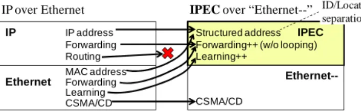
The design policies for IPEC, which is diagramed in Fig- ure 1, are described in this section. As described in Sec- tion 1, the first goal of this development is to develop a
simple single-layer non-IP/non-Ethernet protocol. The second goal is to develop a learning-based forwarding al- gorithm that is applicable to networks with loops. This is intended to keep IPEC as simple as possible.
We have developed the following policies based on the above goals taking into consideration the advantages and disadvantages of IP described in the previous subsection.
• Use of structured addresses and learning: To make IPEC more scalable than Ethernet and to allow structur- ing addresses, ordered addresses similar to IP addresses are used. However, to keep the protocol simple, no routing protocol is to be introduced, and packet forward- ing is based on learning. Extending the learning algo- rithm used by Ethernet switches and applying it to structured addresses is an interesting challenge.
• Two styles of forwarding methods using only one type of address: To allow two styles of packet-forwarding, i.e., Ethernet-style and IP-style, a single type of structured (multi-level) addresses are used. For example, in an en- vironment where LAN and WAN are connected, it is possible to forward packets using individual addresses in LAN and to learn grouped or aggregated addresses and to switch packets using the addresses.
• Applicability to ID/Locator Separation: If addresses with two levels are used, the upper level can be interpreted as a locator and the lower level as a host identifier. If a terminal only knows the host identifier of a destination terminal, the former can communicate more efficiently with the latter without using a locator. In addition, an ID/Locator separation method can be used with IPEC;
namely, terminals can ask a server for the locators of the hosts that the terminals will communicate with.
The first two policies mean that parts of IP and Ethernet were used in designing the refined component, i.e., IPEC.
C. Address- and Protocol-Formats
The hierarchy of addresses can be freely designed on net- work design time with the above design policies. However, simple addresses with two-levels are used in the current implementation. The address and frame formats in this implementation are shown in Figure 2. The structure of addresses (of 8-byte length) is as follows.
• HostID: The lower bits of the address contain the host
IP IP address
Forwarding Routing MAC address Ethernet Forwarding
Learning CSMA/CD
Structured address IPEC Forwarding++ (w/o looping) Learning++
Ethernet-- CSMA/CD
IP over Ethernet IPEC over “Ethernet--” ID/Locator separation
Figure 1. Protocol design policy of IPEC
Total len
Dest addr Src addr Src Grp ID length
Age Payload
Packet format (non-IP)
0 2 10 18 20 22 Byte
Address format
0 4 (variable) 8 Byte
Group ID (network address)
Host ID
Figure 2. Address- and protocol-formats of IPEC
identifier. A Host ID varies in length in the orig- inal design but is fixed at 4 bytes in the current implementation. An ID is atomic; it does not have structure.
• GroupID: The upper bits (the rest) of the address contain the group identifier. The group structure can be hierarchical, but it is assumed to have no structure in this paper.
A group can be interpreted (used) as a locator.
Hosts with the same group ID must exist in the same place, i.e., be connected to the same IPEC WAN switch.
The frame header is 22 bytes long and consists of the following fields from the left.
• Total length: This field contains the sum of header length and payload length.
• Destination address: This field specifies the host address that receives the packet. It follows the above format.
• Source address: This field specifies the host ad- dress that sends the packet. It follows the above format.
• Source group-IDlength: The bit length of group identifi- ers must be specified when it has a variable length. It is fixed at 32 (which means 4 bytes) in the current imple- mentation.
• Age: This field contains the hop value; it is incremented every time the packet transfers between switches. It is similar to TTL in an IP packet and is used to avoid pack- et looping.
D. Method of Learning and Forwarding
The method of forwarding and learning in IPEC WAN, which is called the Learning and Forwarding (L&F) algo- rithm here, is explained in this subsection. IPEC WAN switches only use group IDs for forwarding packets and do not use host IDs. A switch has three or more ports (vir- tual interfaces), and it realizes the same (symmetric) func- tion for all the ports.
The L&F algorithm is divided into two parts: the learn- ing procedure and the forwarding procedure. When a packet arrives at one of the ports, these procedures are applied in this order. The L&F algorithm contains two types of timeout. One is a registration timeout, and the other is a reference timeout. The former is used in the learning procedure, and the latter is used in the forwarding procedure.
The learning procedure is described below. This proce- dure learns the source group and drops packets when ne- cessary. An arrived packet is represented by P, and the forward table entry for P is represented by E.
if source group of P is not registered in the forwarding table then Register group, group length, input port, age of P
to the forwarding table (learn the packet);
else if age of E > age of P or
E is in registration timeout status then age of E = age of P; port of E = port of P;
timestamp of E = current time (ns);
else if age of E < age of P or port of E != port of P then Drop the packet (the forwarding procedure is not applied);
else timestamp of E = current time (ns);
The forwarding table records learned groups. A learned group will be forgotten after a certain amount of time has passed. The registration timeout is used in the learning procedure as follows. If a packet is duplicated and arrives at a switch before the registration timeout, duplicated packets are dropped. Therefore, if there is a short loop (if there are multiple paths) in the network, normally only one packet is forwarded. Infinite duplication of packets that may occur in Ethernet does not occur in IPEC if the trans- mission delay is sufficiently small. However, if a timeout occurs, the duplicated packets are not regarded as copies of the same packet. This timeout was introduced to avoid forwarding failures. If a failure occurs, an alternative path is selected after the timeout. The timestamp of the table entry is updated when the packet is normally forwarded or a timeout occurs.
The forwarding procedure, which is the second part, is described below. In this procedure, a destination port is selected using the destination group in the packet.
if destination group of P is not registered in the forwarding table or E is in reference timeout status then
Flood the packet that is a copy of P but the age is incremented;
else Output the packet that is a copy of P but the age is incremented to the port specified in the registered element;
The reference timeout similar to the Ethernet timeout is used in this procedure. If a reference timeout occurs, the existing forwarding table entry becomes ineffective, and packets that match the entry will be flooded. Namely, cop- ies of the same packet will be output from each port except the arrival port. When no entry is matched, the packet is also flooded.
A possible disadvantage of this L&F algorithm is that there is a risk for a packet to be duplicated. If one of the packets duplicated by flooding arrives at a switch and another copy of the packet with a younger age (with fewer hops) arrives at the same switch after that, both are for- warded.
It is difficult to avoid such duplication completely espe- cially when congestion occurs. However, such duplication probably occurs rarely, and there are several methods that
Node sliver
Node sliver
Node sliver PC 2 IPEC
Soft SW
IPEC Slice
IPEC Soft SW IPEC
Soft
SW Link sliver Link sliver
VNode 1
VNode 3
VNode 2
IPEC Client PC 4 IPEC Client PC 1
IPEC Client
PC 3 IPEC Client Group ID = x00000100 Host ID = x00000011
Group ID = x00000002 Host ID = x80000022
Group ID = x00000030 Host ID = x00000021
Group ID = x00000030 Host ID = x80000022 Link sliver
Len Dest prefix Port Age 32 x00000100 P3 1 32 x00000002 P2 1 32 x00000030 P1 0 Len Dest prefix Port Age
32 x00000100 P2 1 32 x00000002 P1 0 32 x00000030 P3 1 Len Dest prefix Port Age 32 x00000100 P1 0 32 x00000002 P3 1 32 x00000030 P2 1 Forwarding
table
Forwarding
table Forwarding table
P1
P1
P2
P3 P2
P3
P1
P2 P3
loop
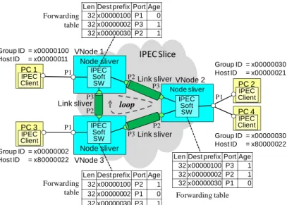
Figure 3. IPEC network structure and status after learning
can avoid or reduce duplication. Two methods are intro- duced here. The first method is as follows. When a route with fewer hops is longer and has long latency, link weights can be introduced to the above algorithm to avoid the problem above; packets can record the travel distance instead of the age. In the second method, an infrequent duplication is not usually fatal when the duplication occurs only once or the number of duplicated packets is reduced rapidly. The number of duplicated packets can be reduced by limiting the age (TTL) or travel distance; namely, the duration of packets can be introduced, and packets that exceed the duration can be dropped.
The above algorithm has been coded in less than 100 lines except for peripheral parts when using C language.
Figure 3 shows an example of a table of contents after learning PC 1, 2, and 3.
III. EXPERIMENT ON A LAN
IPEC has been implemented both in a LAN environment and on a virtualization platform. The implementation and experiment in a LAN are explained in this section.
A. Network Structure and IPEC Implementation
The network used for this experiment is shown in Fig- ure 4. This network consists of six Linux-based PCs: three for software-based IPEC switches and three for terminals (i.e., PC 1 to PC 3). Every terminal group is different from other groups in this experiment because the assumed loca- tion of each terminal is different from others’. Switches are connected using IPEC, and a switch and a terminal are connected by IP/Ethernet. IPEC can also be used on the terminals, but IP/Ethernet is used in order to use IP- and Ethernet-based tools. An IPEC frame can be converted to an IP or Ethernet frame (i.e., IPEC addresses can be trans- lated to IP addresses or MAC addresses). It is converted to an Ethernet frame in this implementation because it is eas- ier. Therefore, when IP over Ethernet is used in the ter- minals, IP over IPEC is also used in the IPEC network.
IPEC has been implemented using promiscuous mode in Linux. If promiscuous mode is used on LAN cards, Ethernet-- protocol in Figure 1 can be used, i.e., the ad- dressing (networking) function of Ethernet can be rendered ineffective; neither packet receiving nor sending opera- tions depend on the Ethernet packet format, so IPEC pack- ets can be used. This means that the hardware and software of the LAN cards are used for producing a refined compo- nent in the network layer and removing addressing func- tion from the link layer (in other words, producing a
refined component in the link layer).
Each switch has four network interfaces, i.e., eth0 to eth3. They are 1000BASE-T or 100BASE-TX cards. Two of the four interfaces are used for IPEC, and the other two are used for Ethernet (one for a terminal and the other for control and monitoring purposes).
The IPEC interfaces are connected one-to-one. Hard- ware repeaters or switches are not required in this experi- ment, but simple repeaters (i.e., dumb hubs) may be used for delivering packets to each PC in an IPEC LAN or for connecting IPEC WAN switches. However, intelligent Ethernet switches cannot be used because they depend on the Ethernet packet format. In addition, most commercially available hubs (i.e., switching hubs) probably cannot be used because they have some intelligence (i.e., they de- pend on the Ethernet packet format).
B. Experiment: Basic Communication
Communication between PC 1 and PC 3 and between PC 2 and PC 3 has been tested, and all PCs were confirmed to- work correctly; no duplicated packets were detected, and they were able to communicate without problems using UDP and TCP, although the performance was rather poor.
We observed the communication by introducing printing functions into the switching programs. We first observed flooding and then observed switching because the IPEC switches learned the groups.
The performance between PCs was around 1 Mbps (measured by iperf command), depending on the per- formance of the hardware. The performance was much lower than expected and could probably be improved.
ARP packets went through the IPEC network because IP over IPEC was used in this implementation. The ARP ta- ble of each PC was assumed to contain the addresses of all the PCs (but we did not look at the ARP tables).
IV. EXPERIMENTS ON THE VIRTUALIZATION PLATFORM IPEC has also been implemented on a virtualization plat- form consisting of four VNode prototypes located at the NICT Hakusan Research Laboratory.
A. Network Virtualization
In the Virtualization Node Project (VNP), network virtua- lization technologies are being developed to build an envi- ronment in which network researchers can develop new protocols with free formats. The availability of free-format protocols is the most outstanding feature of this environ- ment compared to environments developed by other vir- tualization platform research projects including PlanetLab [Pet 03] and GENI [GEN 09]. In this environment, interfe- rences between slices must be avoided, and new- generation (non-IP) protocols can be developed and run without interfering with other slices.
In network virtualization, networks before virtualization and those after virtualization coexist. The former, the low- er-layer network, is called a virtualization platform (or virtualization substrate), and the latter, the upper-layer network, is called a slice or virtual network.
B. Structure of Virtualization Platform and Slice
In the VNP, a virtualization platform (or a domain) has two types of physical nodes (See Figure 5).
PC-based Node
PC-based Node
PC 2 IPEC
Soft SW
IPEC- Ether GW
Physical IPEC Network
PC 3 IPEC Soft
SW IPEC- Ether GW
IPEC I/F IPEC I/F IPEC I/F
IPEC I/F Ethernet I/F
Ethernet I/F Ethernet I/F Ethernet I/F
Ethernet I/F Ethernet I/F Management
PC
PC1
PC-based Node IPEC
Soft SW IPEC- Ether GW
IPEC I/F Ethernet
Figure 4. Network structure for a LAN-based experiment
• VNode is a physical network node that forwards packets on the virtualization platform. Each packet corresponds to a packet on a slice.
• Gateway is a network node that transfers packets be- tween the virtualization platform and another network or user terminals (PCs).
The domain may contain normal nodes, i.e., routers or switches, that do not have virtualization functions.
VNodes are connected by tunnels through such nodes using a tunneling protocol such as Generic Routing En- capsulation (GRE) [Far 00]. Therefore, a virtual network with free topology, which is not constrained by the topol- ogy of the physical network and does not depend on the specific functions of the nodes in between, can be created.
A VNode can be an extended version of a router or a switch, so it can be deployed as an extended version of a conventional network.
Each VNode consists of three components.
• Programmer is a hardware and software component that processes packets on the slices. Slice developers can program programmers.
• Redirector is a hardware and software component that can forward or route packets on the substrate and can forward packets from another VNode to a programmer or forward packets from a programmer to another VNode.
• VNode Manager is a software component that manages the VNode according to instructions from the domain controller (DC).
In the model in the VNP, the virtual network (or a col- lection of resources in a virtual network) is called a slice.
A slice consists of two types of components [Nak 10a].
• Node Sliver represents computational resources that ex- ists in a virtualization node (in a programmer). It is used for node control or protocol processing with arbitrary packet format that may be non-IP. Slow-path node sliv- ers, which are mapped to Linux (Ubuntu) VMs in this prototype, were used in the experiments.
• Link Sliver represents resources of a virtual link that connects two node slivers. A link sliver is mapped to a physical link between two VNodes or a VNode and a Gateway. A link sliver is implemented by using a GRE tunnel in our implementation.
C. Experiment: Switching Based on Group-wise Learning and Motion
The network used for this experiment consists of three node slivers on three VNodes, and three client programs on PCs (terminals) through Gateways (See Figure 6).
Whole network (slice) is an IPEC network in this experi- ment. PC 3 and 4 are IPEC hosts that belong to a group (i.e., they had the same group ID), and PC 1 belongs to another group.
The LAN forwarding function of IPEC, or the host-ID- based switching function, is embedded in the Gateways. If we follow the policy described in Section II, Gateways should learn host identifiers. However, because the Gate- way prototype has not yet been programmable, the pairs of host IDs and terminal IDs must be registered by hand. The Security Parameter Index (SPI) values of IPsec tunnels are
used as terminal IDs because IPsec is used for tunneling between a Gateway and a PC.
The scenario of this experiment is as follows. Initially, PC 1 and PC 3 (under Gateway 3) communicate, but PC 4 does not send any packets. Next, PC 3 moves to the loca- tion of PC 3’ (under Gateway 2) in Figure 6 and connects to Gateway 2. (Actually, we have used different PCs for PC 3 and PC 3’ but the addresses are the same.) Virtually, the PCs belonging to Group 2 move simultaneously from the place of Gateway 3 to that of Gateway 2. PC 3 com- municates with PC 1 again. The switches learn the new location of Group 2 (the group of PC 3 and PC 4). Then, PC 4 communicates with PC 1. Because Group 2 has been learned, PC 4 can communicate without further learning.
We have traced the switches and confirmed that the opera- tion is exactly the same as described above.
D. Performance Measurement
We have measured the performance of IPEC with bidirec- tional IPEC-Ethernet protocol conversion using the net- work shown in Figure 7. This network consists of three node slivers on three VNodes, and three PCs (two servers and one client) through gateways. The node-sliver pro- grams are the same as used in the experiment in the LAN.
Performance between the PC servers and the PC client was measured using iperf command. We used 2-Mbps UDP traffic, and the results shows that the packet loss rate is less than 0.1%. The performance is better than in the LAN environment. We have also measured round-trip time using a ping command. It is 2.8 ms on average.
Gate- way Gate-
way
User’s PC/VM User’s
PC/VM
DC
VNode
VNode VNode
IP
Router VNode
DC: Domain Controller VNode: Virtualization Node VNM: VNode Manager R: Redirector P: Programmer VNode
VNM
P R
Figure 5. Physical structure of virtualization platform
Node sliver
Node sliver
Node sliver PC 4
IPEC Soft SW
IPEC Slice
IPEC Soft SW IPEC
Soft SW
Gate- way 2 Link sliver
Link sliver Gate-
way 3 Gate- way 1
VNode 1
VNode 3
VNode 2
IPEC Client PC 3’
IPEC Client PC 1
IPEC Client
PC 3 IPEC Client Group ID = 256 Host ID = x00000011
Group ID = 2 Host ID = x80000022
Group ID = 2 Host ID = x00000021
Group ID = 2 Host ID = x80000022 Link sliver
Figure 6. Structure of physical network and slice for virtu- alization-platform based experiments (1)
Node sliver
Node sliver
Node sliver
PC Client IPEC
Soft SW
IPEC- Ether GW
IPEC Slice
PC Server
PC Server
IPEC Soft SW IPEC- Ether GW
IPEC Soft SW IPEC- Ether GW
Gate- way 2 Link sliver
Link sliver Link sliver
Gate- way 3 Gate- way 1
VNode 1
VNode 3
VNode 2
Figure 7. Structure of physical network and slice for virtua- lization-platform based experiments (2)
E. Wide-area Experiments and Demonstration
All of the experiments explained in this section have been conducted at the NICT Hakusan Research Laboratory.
However, two wide-area experiments was held in several locations in and near Tokyo. At Interop Tokyo 2010 in Makuhari, two VNodes in Makuhari and one VNode in Hakusan formed the network shown in Figure 6. At Inte- rop Tokyo 2011 in Makuhari, three VNodes in Makuhari, Mejirodai, and Hakusan formed the network shown in Figure 7. The same results as described in the previous subsections was reproduced in these experiments. The VNodes have been introduced into a research-purpose na- tional experimental network called JGN-X, so we will pre- pare for new wide-area experiments using IPEC.
At the 8th GENI Engineering Conference (GEC8), Na- kao, a co-author, have introduced IPEC as an example application of the virtualization platform, and posted the demonstration video on the Web[Nak 10c]. In this video, a reply by a PC to an initial communication request by another PC is intentionally delayed to visualize the flood- ing operation. After the delayed reply, the switching opera- tion can be observed.
V. RELATED WORK
Transparent Interconnection of Lots of Links (TRILL) [Tou 09] introduces routing function into Ethernet. TRILL is not intended to replace the layer-3 protocol, i.e., IP, so it doubles routing function. Therefore, TRILL increases the complexity of the protocol stack in contrast to IPEC that reduces the complexity.
Locator/ID Separation Protocol (LISP) [Far 11] in- creases scalability of the Internet by introducing multi- level addresses. The purpose of LISP is similar to that of IPEC, but it is not a clean-slate approach. It is applied to IP networks and it makes the networks, which has been al- ready complicated, more complicated. IPEC is less scala- ble than LISP but it is much simpler.
In contrast to most textbooks on computer networks which use layer-based approach, Peterson and Davie [Pat 11] describe Ethernet and IP as comparable protocols for internetworking. This view is similar to that described in Section 1. However, they do not compare Ethernet and IP directly and do not discuss the complexity caused by their combination.
VI. CONCLUSION
A non-IP/non-Ethernet protocol called IPEC has been de- veloped. IPEC is a simple non-IP network-layer protocol that has features of both Ethernet and IP or that is designed as an Ethernet- and IP-based refined component. Because an address group is the unit of learning in IPEC, it is more scalable than Ethernet, and a mobile group can be more efficiently learned. Furthermore, this forwarding algorithm can be used in networks with loops under the condition that a limited number of packet duplications is allowed, and it can forward packets even when a failure occurs us- ing an alternative path. Group IDs can be used as locators.
IPEC has been implemented and tested both using IPEC-capable switches using LAN cards and promiscuous mode to produce refined components, and using the virtua- lization platform. We show evaluations that the group
learning function of IPEC is viable especially for multiple terminals moving together concurrently. In this implemen- tation, the sizes of the group and host identifiers are fixed, and no aggregation algorithm has been implemented. In the future, we plan to implement and evaluate an aggrega- tion algorithm.
ACKNOWLEDGMENT
We thank Akihiro Motoki from NEC, Watanabe Norikazu from Fujitsu, Makoto Kitani from Alaxala Networks, and other members of the VNP for their assistance and helpful comments on the design and implementation of IPEC.
REFERENCES
[AKA 10] AKARI Architecture Design Project, “New Genera- tion Network Architecture―AKARI Conceptual Design (ver 2.0)”, http://akari-project.nict.go.jp/eng/concept-design/- AKARI_fulltext_e_preliminary_ver2.pdf, May 2010.
[Aoy 09] Aoyama, T., “A New Generation Network: Beyond the Internet and NGN”, IEEE Communications Magazine, Vol. 47, Vol. 5, pp. 82–87, May 2009.
[Bon 10] Bonaventure, O., “Computer Networking: Principles, Protocols and Practice”, Release 0.0, (Chapter 6), https://scm.info.ucl.ac.be/release/cnp3/Book/0.0/CNP3.pdf . [Bus 02] Bush, R. and Meyer, D., “Some Internet Architectural
Guidelines and Philosophy”, RFC 3439, IETF, December 2002.
[Far 00] Farinacci, D., Li, T., Hanks, S.,. Meyer, D., and Trai- na, P., “Generic Routing Encapsulation (GRE)”, RFC 2784, IETF, March 2000.
[Far 11] Farinacci, D., Fuller, V., Meyer, D., and Lewis, D.,
“Locator/ID Separation Protocol (LISP)”, Internet Draft (Work in progress in 2011).
[Fel 07] Feldmann, A., “Internet Clean-Slate Design: What and Why?”, ACM SIGCOMM Computer Communication Review, Vol. 37, No. 3, pp. 59–74, July 2007.
[Fin 84] Finlayson, R., Mann, T., Mogul, J. C., and Theimer, M., “A Reverse Address Resolution Protocol”, RFC 903, IETF, June 1984.
[GEN 09] The GENI Project, “Lifecycle of a GENI Experi- ment”, GENI-SE-SY-TS-UC-LC-01.2, April 2009, http://groups.geni.net/geni/attachment/wiki/ExperimentLifecy cleDocument/ExperimentLifeCycle-v01.2.pdf?format=raw . [IEE 04] IEEE Computer Society, “802.1D: IEEE Standard for
Local and Metropolitan Area Networks―Media Access Con- trol (MAC) Bridges”, 2004.
[Nak 10a] Nakao, A., “Network Virtualization as Foundation for Enabling New Network Architectures and Applications, IEICE Trans. Commun., Vol. E93-B, No. 3, pp. 454–457, March 2010.
[Nak 10b] Nakao, A., “Virtual Node Project―Virtualization Technology for Building New-Generation Networks”, NICT News, No. 393, pp. 1–6, Jun 2010.
[Nak 10c] Nakao, A., “Update on CoreLab and VNode”, http://groups.geni.net/geni/attachment/wiki/Gec8Agenda/- GEC8_Aki-slides%2Bvideo.zip .
[Nar 07] Narten, T., Nordmark, E., Simpson, W., and Soliman, H., “Neighbor Discovery for IP version 6 (IPv6)”, RFC 4861, IETF, September 2007.
[Pat 11] Peterson, L. L. and Davie, B. S., “Computer Net- works, Fifth Edition: A Systems Approach”, Morgan Kauf- mann, 2011.
[Pet 03] Peterson, L., Anderson, T., Culler, D., and Roscoe, T.,
“A Blueprint for Introducing Disruptive Technology into the Internet”, ACM SIGCOMM Computer Communication Re- view, Vol. 33, No. 1, pp. 59–64, January 2003.
[Plu 82] Plummer, D., “Ethernet Address Resolution Protocol:
Or Converting Network Protocol Addresses to 48-bit Ethernet Address for Transmission on Ethernet Hardware”, RFC 826, IETF, November 1982.
[Tou 09] Touch, J. and Perlman, R., “Transparent Interconnec- tion of Lots of Links (TRILL): Problem and Applicability Statement”, RFC 5556, IETF, May 2009.