• 検索結果がありません。

A change in the firing current gives rise to an electromotive force in adjacent circuits consisting of conductors and the bridgewires of fuseheads.

N/A
N/A
Protected

Academic year: 2021

シェア "A change in the firing current gives rise to an electromotive force in adjacent circuits consisting of conductors and the bridgewires of fuseheads."

Copied!
3
0
0

読み込み中.... (全文を見る)

全文

(1)

1. Introduction

Electric ignition systems for launching fireworks have been gaining in popularity because of the ease of precisely controlling the launch timing and the ability to employ a remote control system, thus ensuring the safety of the operator. When a series of fireworks are launched in a display, a large number of fuseheads for igniting the lift charges of the firework shells are connected to the firing cables and await the firing signals. For convenience, multi- conductor cables are sometimes used instead of a large number of individual firing cables. However, when conductors are laid closely together in a cable, electromagnetic induction can occur among them, and this has been the subject of a considerable amount of research in a number of fields.

1)-4)

A change in the firing current gives rise to an electromotive force in adjacent circuits consisting of conductors and the bridgewires of fuseheads.

If a circuit is closed by accidental or inadvertent shorting of a conductor at the end opposite to the fusehead, the electromotive force will induce a current in the bridgewire. If the induced current is sufficiently large, an unexpected ignition of the fusehead can take place.

In the present study, numerical calculations were carried out to investigate the possibility of such ignition occurring due to electromagnetic induction. Although various kinds of electric ignition systems are employed for

fireworks displays, the system considered here involved multi-conductor cables since such cables are becoming more commonplace.

2. Calculation model

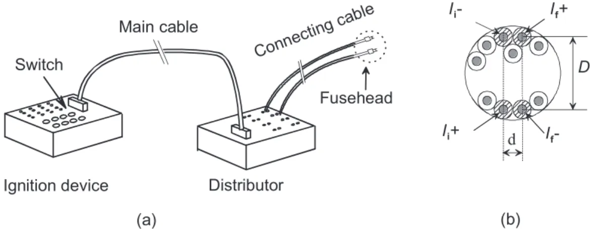
A typical electric ignition system for launching fireworks is shown in Figure 1 (a). The ignition device contains batteries whose output voltage is several tens of volts, and switches with mechanical contacts to start the firing currents. A distributor is connected to the ignition device by a main multi-conductor cable and the firing currents are fed to a group of fuseheads through connecting cables.

The entire ignition system can be represented by a simple LR circuit, as shown in Figure 2, where &

!

is the battery voltage, "

%

is the firing current and "

&

is the induced current to be solved. The sum of the resistances and self- inductances attributed to the ignition device, the main cable, the connecting cable and the fusehead in a circuit in which a current "

%

is flowing is denoted by %

"

and #

"

, respectively. Except for the contribution of the ignition device, %

#

and #

#

are similarly defined in a circuit with a current "

&

flowing. The mutual inductance between two conductors with currents "

%

and "

&

in the main cable is indicated by $.

As typical multi-conductor cables for the numerical

Possibility of ignition of electric fusehead due to electromagnetic induction

Dongjoon Kim

*†

, Shu Usuba

, Yozo Kakudate

, and Shuzo Fujiwara

Research Institute of Science for Safety and Sustainability, National Institute of Advanced Industrial Science and Technology, 1­1­1 Higashi, Tsukuba, Ibaraki 305­8565, Japan

Phone : +81­29­861­4788

Corresponding address : blastwaves@hotmail.com

Received : September 6, 2012 Accepted : November 21, 2012

Abstract

The electromagnetic induction effect has been investigated for an electric ignition system with a multi-conductor cable commonly used for launching a series of fireworks in a firework display. The results show that the energy consumed in a bridgewire (!

$

) may have a value close to the minimum energy required to ignite a fusehead, depending on the type of cable and the way it is used. In addition, it was found that chatter in a mechanical switch can cause a further increase in

!

$

, possibly leading to unintentional ignition.

Keywords : fusehead, ignition, electromagnetic induction, chatter

Letter

Sci. Tech. Energetic Materials, Vol. 74, No. 2,2013 47

(2)

Ignition device Distributor Main cable

Con nec ting ca ble Switch

Fusehead

I

f

+

I

f

- I

i

-

I

i

+

D

(b) (a)

d

V

0

Switch

L

1

R

1

L

2

R

2

M

I

f

I

i

0 50 100 150

0 5 10

I

i

I

f

V

0

Induc e d cu rre n t, I

i

[ A ]

Fi ri ng v o ltage, V

0

[ V ] Fi ri ng cu rre n t, I

f

[ A ]

0 10 20 30

0 1 2

Time [ s]

calculations, cables with 20 or 40 conductors specified in the Japanese Industrial Standard JIS C3312 (see Table 1) were chosen. The magnitude of the electromagnetic induction in the cable depends on which pair of conductors is selected as the feed path for firing and the return path for the induced current. Because we are most concerned with the worst-case scenario of unexpected ignition, it was decided to consider the largest possible mutual inductance, obtained by maximizing the area of the current loops and minimizing the distance between the loops. The calculations for $ were thus based on the geometrical arrangement of conductors shown in Figure 1 (b), where the positive sign indicates the feed path, and the negative sign indicates the return path. The contribution of the ignition device to %

"

and #

"

was determined so as to reproduce the measured current waveforms for a given &

!

when the output terminals of the ignition device were shorted. The resistances %

"

and %

#

were measured directly, and the self-inductances #

"

and #

#

were calculated from the geometrical arrangement of the current path. The shape of the connecting cable used for calculating its contribution to #

"

and #

#

was based on JIS C3306.

The energy consumed in the bridgewire of the fusehead (!

)

) was determined using the calculated "

+

and the resistance of the bridgewire, and was compared with the

minimum ignition energy

5)

of the fusehead in order to discuss the possibility of ignition occurring.

3. Results and discussion

Figure 3 shows an example of calculated time profiles for "

*

and "

+

, where &

!

!#%V, the main cable has 20 conductors and its length is 20 m, and no connecting cable is present. This model assumes that &

!

is applied instantaneously, and held constant because of difficulty in quick break by the mechanical switch. Therefore, "

+

is a single short current pulse, and has a duration of several tens of microseconds corresponding to the rise time of "

*

upon the application of &

!

.

The dependence of !

)

on the length of the main cable was first investigated. When the main cable is sufficiently short, !

)

increases with length because $ also increases with length. However, for a sufficiently long main cable, "

+

is dominated by the product of two effects related to the length. The first is that an increase in #

"

causes an increase in the rise time of the firing current due to a decrease in the electromotive force. The second is that an increase in #

#

leads to a decrease in "

+

because #

#

acts as a load in the same manner as %

#

. As a result, it is found that

!

)

has a broad maximum around a cable length of a few tens of meters.

Table1 Parameters for multi­conductor cables.

Number of conductors

Nominal conductor cross­sectional area

(mm

)

d (mm)

D (mm)

20 0.5 0.5 8.0

40 0.75 0.6 14.8

Figure1 Typical electric ignition system for launching fireworks (a) and cross­sectional view of a multi

­conductor cable used in the system (b).

Figure2 Electrical circuit representing electromagnetic induction effect in ignition system.

Figure3 Time profiles of firing current, "

*

, and induced current, "

+

, when a voltage, &

!

, is applied instantaneously. Values of the parameters used in the calculation are as follows ; &

!

!#% ! ! V, %

"

!# ! '#

" , #

"

!$" ! & # H, $!"" ! ' # H, %

#

!# ! (' " and

#

#

!#% ! ' # H.

Dongjoon Kim et al.

48

(3)

0 40 80 120 1E-3

0.01 0.1 1 10

Case 3 Case 1 Case 2

E

B

[m J]

V

0

[V]

0.0 0.5 1.0 1.5 2.0 2.5

-0.6 -0.4 -0.2 0.0 0.2 0.4 0.6

Current [ A ]

Time [ms]

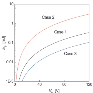
Figure 4 shows the calculated dependence of !

#

on &

!

for a main cable with the length of 20 m. The minimum energy required to ignite a fusehead ( !

$

) is compared with

!

#

to judge whether the fusehead ignites or not, and a value of !

$

has been investigated by many researchers

5)-8)

. Our recent study on a type of fusehead widely used in Japan

5)

showed that !

$

strongly depends on the duration of the firing current pulse, that is, decreases from about 3 to 1.5 mJ as the duration is decreased from about 10 to 0.1 ms. Since the duration of "

&

is several tens of microseconds,

!

$

is expected to approach asymptotically to about 1 mJ.

Thus, in the present study, !

$

is assumed to be 1 mJ, as indicated by the horizontal line in Figure 4. It can be seen from the figure that for a 20-conductor cable without any connecting cable (Case1), when &

!

is 24 V, !

#

is about 1%

of !

$

. Even if &

!

is increased to 100 V, !

#

is only about 10%

of !

$

, so that ignition is unlikely to occur. On the other

hand, for a 40-conductor cable without any connecting cable (Case2), !

#

is almost ten times larger than that for Case 1. In this case, if &

!

is 100 V, the possibility of ignition cannot be disregarded. The larger induction effect for Case 2 is attributed to an increase in $. In this case, the increased area of the "

&

and "

%

loops has a large effect despite the increased distance between the two loops.

However, if a connecting cable with a length of 10 m is then added (Case3), !

#

is reduced considerably due to increases in %

"

and #

"

.

When carrying out preliminary experiments to determine the circuit parameters for the ignition device for use in the calculations, an interesting phenomenon was found. Figure 5 shows the measured current induced by an ignition device with a mechanical firing switch, and it can be seen that several positive or negative current spikes occurs over a period of several milliseconds. These are due to chatter in the switch, which is the unwanted bouncing of the mechanical contact. Because the energy consumed in the bridgewire is the accumulation of that associated with each of these individual spikes, a further increase in !

#

is possible when a mechanical switch is employed, even if the battery voltage is only a few tens of volts.

4. Conclusions

Numerical calculations were carried out to investigate the influence of electromagnetic induction in an electric ignition system with the type of multi-conductor cables commonly used for launching fireworks. The results show that the energy consumed in a bridgewire may have a value close to the minimum energy required to ignite a fusehead, depending on the type of cable and the way it is used. Furthermore, chatter associated with a mechanical switch may lead to a further increase of !

#

, possibly leading to unintentional ignition.

References

1) K. Taniguchi, Kogyo Kayaku (Sci. Tech. Energetic Materials), 37, 144­151 (1976) (in Japanese).

2) K. Taniguchi, Kogyo Kayaku (Sci. Tech. Energetic Materials), 38, 3­9 (1977) (in Japanese).

3) K. Taniguchi, K. Inoue, E. Yamakawa, and H. Sakai, Kogyo Kayaku (Sci. Tech. Energetic Materials), 39, 261­265 (1978) (in Japanese).

4) A. Nagaoka and M. Sakaguchi, Kogyo Kayaku (Sci. Tech.

Energetic Materials), 45, 33­37 (1984) (in Japanese).

5) D. Kim and Y. Kakudate, Sci. and Tech. Energetic Materials, 73, 42­46 (2012).

6) E. Jones, Proceedings of the Royal Society of London, 198, 523­539 (1949).

7) K. Kato, Kogyo Kayaku (Sci. Tech. Energetic Materials), 20, 286­291 (1959) (in Japanese).

8) R. Akiba and S. Kayuta, Kogyo Kayaku (Sci. Tech.

Energetic Materials), 27, 349­354 (1966) (in Japanese).

Figure4 Dependence of energy consumed in bridgewire (!

#

) on battery voltage (&

!

).

Figure5 Time profile of induced current caused by chatter in mechanical switch.

Sci. Tech. Energetic Materials, Vol. 74, No. 2,2013 49

Figure 3 shows an example of calculated time profiles for "* and "+ , where & ! !#%V, the main cable has 20 conductors and its length is 20 m, and no connecting cable is present
Figure 4 shows the calculated dependence of ! # on & ! for a main cable with the length of 20 m

参照

関連したドキュメント

An example of a database state in the lextensive category of finite sets, for the EA sketch of our school data specification is provided by any database which models the

The input specification of the process of generating db schema of one appli- cation system, supported by IIS*Case, is the union of sets of form types of a chosen application system

Thus, in Section 5, we show in Theorem 5.1 that, in case of even dimension d > 2 of a quadric the bundle of endomorphisms of each indecomposable component of the Swan bundle

In this case, the extension from a local solution u to a solution in an arbitrary interval [0, T ] is carried out by keeping control of the norm ku(T )k sN with the use of

In the second computation, we use a fine equidistant grid within the isotropic borehole region and an optimal grid coarsening in the x direction in the outer, anisotropic,

Thus, we use the results both to prove existence and uniqueness of exponentially asymptotically stable periodic orbits and to determine a part of their basin of attraction.. Let

Here we continue this line of research and study a quasistatic frictionless contact problem for an electro-viscoelastic material, in the framework of the MTCM, when the foundation

We present sufficient conditions for the existence of solutions to Neu- mann and periodic boundary-value problems for some class of quasilinear ordinary differential equations.. We