1. Introduction
When an explosive detonates in a decoupled borehole, a shock wave is generated in the air channel between the explosive charge and the inner wall of the borehole. As the velocity of the precursor air shock wave (PAS) propagat- ing in the air channel is higher than that of the detonation wave in the explosive under some conditions, the shock wave travels ahead of the detonation wave. This PAS, which propagates ahead of the detonation wave, precom- presses the unreacted explosive and desensitizes the explo- sive charge. When the detonation wave reaches this pre- compressed point, the detonation wave ceases to propagate regularly. Thus, the decrease in detonation velocity and a detonation failure occurs. This phenomenon is well known as the channel effect. Several works on the channel effect have been conducted under various conditions, using com- mercial explosives
1)-4). Visual studies of the channel effect have been reported by a few researchers
5)-8).
In order to clarify the cause of the channel effect, it is necessary to elucidate detonation propagation in explosive charges and progress of the PAS in the air channel. A pho-
tographic observation using a high-speed framing camera was carried out to study the mechanism of the channel effect.
2. Experimental 2.1 Explosives
Typical water-in-oil emulsion explosives were used in these experiments. The emulsion matrix consisted of 84 % oxidizing agent, 11 % water and 5 % fuel oil and emulsi- fier. Microbubbles create the necessary hot spots for sen- sitizing the explosive. Three kinds of resin microbubbles (RMBs) were added as sensitizer to the emulsion matrix to adjust the initial explosive density to 1000 kg
•m
-3. The detonation velocity of sample explosives was controlled in the range 3000 - 4900 m
•s
-1by the choice of RMB.
Three kinds of explosives were used in test series A. Table 1 shows the properties of those three kinds of explosives under unconfined conditions.
Under high pressure, glass microbubbles (GMBs) in an emulsion explosive generally crack and their structures are crushed. Then, the sensitivity of the explosive decreases.
Photographic study of channel effect on emulsion explosives
Fumihiko Sumiya *
†, Yoshikazu Hirosaki * , Yukio Kato * , Yuji Wada ** , Yuji Ogata ** , and Kunihisa Katsuyama ***
*NOF Corporation Taketoyo Plant, 61-1 Kita-komatsudani, Taketoyo-cho, Chita-gun, Aichi 470-2398, JAPAN
†
Corresponding address: [email protected]
**National Institute of Advanced Industrial Science and Technology(AIST), 16-1 Onogawa, Tsukuba, Ibaraki 305-8569, JAPAN
***Dept. of Rural Engineering, Faculty of Agriculture, Ehime University, 3-5-7, Tarumi, Matsuyama, Ehime 790-8566, JAPAN
Received: May 1, 2006 Accepted: August 24, 2006
Abstract
The precursor air shock wave (PAS) in air channel, which propagates ahead of the detonation front, precompresses and desensitizes the unreacted explosive charges. On some conditions, the PAS leads to the failure of explosive detonation.
This phenomenon is commonly known as the channel effect. To investigate the mechanism of the channel effect in emul- sion explosives in the case of smooth blasting, some experimental work has been carried out using a high-speed framing camera. The results of photographic investigation demonstrate that the compression time by PAS caused by the difference between PAS velocity and detonation velocity is the primary factor for the occurrences of the channel effect.
Keywords : Emulsion explosive, Channel effect, Photographic, Precursor air shock wave (PAS)
Research
paper
The RMBs are also compressd and shrunk under high pressure. However, the shape of RMB will be restored when the pressure is released. The choice of the microbub- bles is a key point whether an explosive can keep propa- gating under high pressure due to PAS. RMBs of higher strength were chosen in our experiments in comparison with GMBs.
2.2 Experimental arrangements
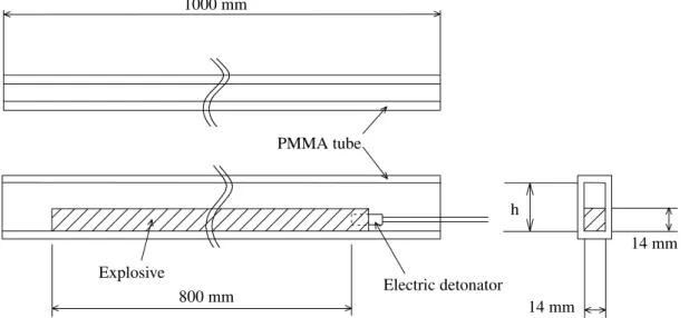
Figure 1 shows the experimental arrangement. An emul- sion explosive was charged in a transparent tube with rectangular cross section, which was made of 4 mm thick polymethylmethacrylate (PMMA) plates. The length of this tube was 1000 mm. The inner width of the tube was maintained to be 14 mm, but the inner height was changed to modify the tube geometry. The reason for using tube with rectangular cross section is the difficulty of pho- tographing a cylindrical tube. The decoupling index is defined in this paper as the ratio of the inner wall height of the rectangular PMMA tube to the explosive charge height.
The explosive charge height in the experiment was kept to be 14 mm. The sample emulsion explosive occupied the volume of 14 × 14 mm in cross section, and over 800 mm in length. Electric detonator was inserted into emulsion explosive. And explosive length from the top of detonator to the end of explosive was adjusted to be 800 mm.
Both ends of the tube were opened not to be choked. So, initial pressure of air channel was kept at atmospheric con- ditions.
2.3 Photographic observation system
The propagation of the detonation wave and the PAS was observed using a high-speed framing camera (Cordin model 124). This camera can take 26 pictures at a fram- ing rate of 1.0 × 10
5– 2.5 × 10
6frames per second (FPS).
In our experiments, a framing rate of 1.0 × 10
5– 5.0 × 10
5FPS was used and the interframe time was 2 – 10 µs. A Xenon flash was served as a light source. The electric det- onator was controlled within 1 µs precision for initiation and synchronized with the framing camera and the Xenon flasher. Photographic observations were conducted from the side face of the PMMA tube. Using the sequential pho- tographs taken, the position of the PAS was defined as the point of the middle of luminous area. And the position of detonation front was determined as the intersecting point of the lower horizontal line for explosive column with the lower oblique line for explosion product.
3. Results and discussion
In test series A, a study on the influence of the detonation velocity on detonation propagation was conducted. And in the test series B, a study on the influence of the geometric conditions was conducted.
The PAS, propagating faster than the detonation wave, was observed in the experiments using a rectangular PMMA tube. The PAS emitted high intensity visible light over 100 – 200 mm in length. Because the PAS was self- luminous, the PAS front could not be identified. However, no PAS was observed in experiments using a PMMA tube without the confining roof.
Table 1 Properties of emulsion explosives.
Explosive
1 2 3
450 90 45
1000 1000 1000
3100 – 3300 4200 – 4400 4700 – 4900
7 – 8
< 5
< 5 Density
(kg
・m
-3)
Unconfined VOD (14 mmj, m
・s
-1) RMB average
diameter (µm)
Critical diameter
(mm)
1000 mm
14 mm Electric detonator
800 mm
14 mm h
Explosive
PMMA tube
Fig. 1 Sample explosive in PMMA tube.
The detonation velocity was very much reproducible with- in ±100 m
•s
-1along the whole length of the rectangular PMMA tube, except in the case of detonation failure.
3.1 Influence of the detonation velocity on the detonation propagation
The experimental results for the test series A are shown in Table 2.
Detonation failure was observed in the experiment No.
A-1. As can be realized in Table 2, the detonation veloci- ties of the three explosives charged into the PMMA tube were within the same range as previously shown in Table 1 for unconfined charges. Therefore, it is concluded that the confinement of the PMMA tube doesn’t extremely influ- ence the detonation velocity.
The PAS velocity of the explosives with high detonation velocity was higher than that of the explosives with the lower detonation velocity. However, the ratio of the PAS velocity to the detonation velocity increases with decreas- ing detonation velocity.
Figure 2 shows the schematics of Mach reflection of the air shock in the channel based on the theory. When an explosive detonated in a PMMA tube, it was observed that the angle (“b” in Fig. 2) between the products/air interface caused by the detonation and the axis of the explosive charge depended on the type of the explosive. The degree of angle b observed in our experiments is shown in Table2.
The angle b for explosive type 1 was larger than that
for explosive type 3. This angle is smaller than an angle (“a” in Fig. 2) between the invisible shock wave caused by detonation and the axis of the explosive charge. It is assumed that in the case with explosive type 1, the shock wave in the air channel reaches the upper wall in a shorter time than in the other experiments. Therefore, an explosive with lower detonation velocity will give a PAS with higher relative velocity than an explosive with higher detonation velocity.
It is assumed that precompression caused by the PAS gives various effects on its detonation propagation depend- ing on the type of emulsion explosives. No detonation fail- ure was observed in our experiments using the explosive types 2 and 3. However, as long as there is a difference between the detonation velocity and the PAS velocity, time necessary for the PAS to desensitize the explosive will be available later during detonation propagation. A detona- tion failure may occur in such a situation. However, it is concluded that the enhancement of explosive performance, especially by means of the detonation velocity, is one of the effective methods to prevent a detonation failure.
In actual blasting scene, an explosive with higher detona- tion velocity releases a higher shock pressure to the rock in a borehole. If such an explosive is placed at the limit of excavation contour, the fractures and breakages extend beyond this limit and into the rock mass. This is the reason why explosives with higher detonation velocity cannot be used for smooth blasting techniques.
Table 2 Experimental results of test series A.
Experiment no.
Explosive type
Decoupling index (= h / 14)
Propagation length
(mm)
Detonation velocity (m
・s
-1) (X)
PAS velocity (m
・s
-1) (Y)
Velocity ratio (Y/X)
Angle b in Fig. 2 (degree) A-1
A-2 A-3 A-4 A-5 A-6
1 1 2 2 3 3
2.00 3.00 2.00 3.00 2.00 3.00
490 800 800 800 800 800
3120 3110 4350 4390 4850 4800
3900 3550 4840 4730 5190 5040
1.25 1.14 1.11 1.08 1.07 1.05 Decoupling index ; inner height of PMMA tube / explosive height = h / 14
60-65 45-55 40-50
a b Products
Confinement Explosive
Co
1.
2.
3.
4. 5.
6.
7.
1. Air shock front 3. Mach stem shock front 4. Triple point
5. Reflected shock 6. Triple point trajectory 7. Detonation front A
Confinement
2. Products / Air interface Air channel
Fig. 2 Theoretical schematics of Mach reflection.
It was considered that self-luminous point was very high temperature. Based on the PAS velocity evaluated from the photographs, the temperature T
1and the pressure P
1were calculated by using the following equation.
T
1/ T
0= [2+(g-1)M
2][2gM
2-(g-1)] / (g+1)
2M
2P
1/ P
0= 1+(M
2-1)2g / (g+1)
where the initial temperature T
0was 298 K, the initial pressure P
0was 0.1 MPa. M was Mach coefficient, which meant the PAS velocity / the speed of sound. The g was the ratio of specific heat whose value was 1.4.
As a result of calculation, we found out that the tempera- ture T
1was the range of 6250 – 14600 K, the pressure P
1was the range of 12 – 29 MPa. Tanguay et al.
7)described the shock temperature and pressure obtained with com-
puter code regarding the shock wave with a velocity of 5 km
•s
-1. These values give 7866 K and 32.8 MPa. Both his result and our calculation results are in similar range of temperature and pressure. Anyway, emulsion explosives were exposed under the drastic conditions.
3.2 Influence of the geometric conditions on the propagation of the detonation wave and the PAS
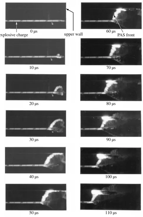
These experiments were conducted using the explosive type 1. Figure 3 shows a sequence of high-speed framing photographs obtained in the experiment No. B-11. These photographs clearly illustrate Mach reflection of the PAS driven by detonation products and the formation of Mach stem at the ceiling of PMMA tube as previously shown in Fig. 2.
explosive charge 0 µs upper wall 60 µs PAS front
10 µs 70 µs
20 µs 80 µs
30 µs 90 µs
40 µs 100 µs
50 µs 110 µs
Fig. 3 Sequence of high-speed framing photographs.
Experimental results in test series B are shown in Table 3. The detonation wave propagated with almost the same velocity in all experiments. In the experiment with the smaller decoupling index, the PAS gave a higher relative velocity than that for larger decoupling index. In these experiments, the detonation propagation distance increases with increasing decoupling index but decreases with increasing PAS velocity.
The detonation failure was observed in experiments Nos.
B-2 − B-7, for which the decoupling index varied within the range 1.21 − 2.71. Johansson et al.
1)concluded that detonation failure in dynamite of diameter 25 mm occurs in the range of decoupling index 1.12 – 3.82. Liu et al.
4)described that for an emulsion explosive of charge diam- eter 25 mm, the detonation failure occurs in the range of decoupling index 1.28 – 3.56.
It is considered that the detonation failure is depen- dent on both the decoupling index and the diameter of the explosive charge. When the decoupling index is suf- ficiently large, the PAS precompressing the explosive scarcely travels ahead of the detonation wave. In addition, the channel effect is a characteristic of an explosive charge whose diameter is as small as its critical diameter. When the explosive diameter is large enough, the PAS will not be able to compress the explosive to cause a detonation failure. Our experimental scale was relatively small and the explosive diameter was close to the critical diameter.
Consequently, the range of the decoupling index in which the detonation failure occurred was different from that obtained by previous researchers.
There were differences with respect to test conditions, too. They used a tube with circular cross section, and we used a tube with rectangular cross section. Considering the different decoupling index range for the channel effect in the two geometries, it is concluded that the condition with circular cross section is more difficult for detonation propagation when compared with that of a rectangular cross section. Our earlier experiments confirmed that in a circular cross section tube, detonation failure occurred
at a decoupling index of 3.00 in a charge of 15 mm in diameter
9).
It is considered that time interval during which the unre- acted explosive charge is precompressed by the PAS is very important factor in the channel effect. If the distance between the PAS front and the detonation front becomes long enough, the PAS will compress a layer of explosive thick enough to prevent further propagation of the detona- tion at this compressed point of the explosive charge. We define the critical length and critical time as follows.
Critical length;
[travel length of the PAS at detonation failure]
- [length of propagation of detonation up to the point of detonation failure]
Critical time;
[time from initiation to detonation failure]
- [time elapsed when the PAS reaches the point of the detonation failure]
From experimental results shown in Table 3, it is estimat- ed that the critical time is 50 – 60 µs and the critical length is about 200 mm. Bjarnholt et al.
5)concluded that a critical time for compression was about 90 µs in their experiments using Gurit explosive, which is a powder explosive sensi- tized by NG/EGDN and SiO
2is added as inert material.
3.3 Compression speed of emulsion explosive by the PAS
Compression speed of unreacted emulsion explosive by the PAS was estimated by means of using several sheets of close-up photographs at the point of detonation failure.
That speed could be estimated to be approximately 120 – 170 m
•s
-1. Independent of the hardness of the explosive charge, the compression speed is considered to be almost the same for all kinds of explosives. Smedberg et al.
6)reported that the compression speed was estimated to 350 m
•s
-1on their experiments using emulsion explosive.
As mentioned in previous paragraph, the critical time for compression is approximately 50 µs. From these photo- graphs, the thickness of the unreacted explosive is reduced Table 3 Experimental results of test series B.
Experiment no.
Decoupling index (= h / 14)
Propagation length
(mm)
Detonation velocity (m
・s
-1) (X)
PAS velocity (m
・s
-1) (Y)
Velocity ratio (Y/X)
Critical length
(mm)
Critical time
(µs) B-1
B-2 B-3 B-4 B-5 B-6 B-7 B-8 B-9 B-10 B-11
1.00 1.21 1.50 1.79 2.00 2.29 2.71 3.00 4.00 5.00 7.00
800 410 400 500 490 580 610 800 800 800 800
3200 3080 3130 3170 3120 3130 3180 3110 3100 3130 3100
3200 3860 4060 4020 3900 3800 3840 3550 3450 3430 3290
1.00 1.28 1.30 1.27 1.25 1.21 1.21 1.14 1.11 1.10 1.06
— 180 210 170 180 180 180
—
—
—
—
— 60 60 50 50 50 50
—
—
—
— Critical length ; [travel length of the PAS at detonation failure] – [length of propagation of detonation up to the point of detonation failure]
Critical time ; [time from initiation to detonation failure] – [time elapsed when the PAS reaches the point of detonation failure]
エマルション爆薬におけるチャンネル効果の光学的検討
角谷文彦 *†,廣崎義一 *,加藤幸夫 *,和田有司 **,
緒方雄二 **,勝山邦久 ***
穿孔内に装薬された爆薬が爆轟したときに,爆薬薬包と穿孔内壁との間に空間が存在すると,その空間の中 を爆轟波に先行して伝播する衝撃波が生じる。これを先行衝撃波と言い,この衝撃波が反応を起こしていない 爆薬を加圧し,不感度化する。さらにある条件において爆轟伝播が中断する。この現象はチャンネル効果とし てよく知られている。
制御発破工法の一手法であるスムースブラスティング工法において,エマルション爆薬におけるチャンネル 効果の発生機構を調査するため,高速度カメラを用いて種々の実験を行った。
この光学的検討によりチャンネル効果の発生要因として,先行衝撃波速度と爆轟波速度との違いに起因する,
先行衝撃波による爆薬の加圧時間が重要な要因であることが判明した。
*
日本油脂(株)・武豊工場 〒 470-2398 愛知県知多郡武豊町北小松谷 61-1†Corresponding address: fumihiko̲[email protected]