Introduction
The incidence of proximal femur fractures is continuing to increase in Japan
1)-3). An estimated 180,000 patients had hip fractures in 2010. The age-adjusted incidence of hip fractures in Western countries is reportedly decreasing
4)-7), although the percentage of comminuted proximal femur fracture is reported to be increasing
8). The reason for the de- clining incidence going into the 21st century, despite the ag- ing of society and increase in the elderly population in all countries, is unknown.
Early surgical treatment is recommended for proximal fe- mur fractures
9)-11). Treatment with a combination of lag
screw and plate or intramedullary nail are widely used
12), 13). Several types of lag screws and insertion angles of plate and nail have been developed to provide better treatment out- comes. However, because Asians usually have a smaller body constitution, including smaller femoral neck geometric parameters than Caucasians
14), implants developed in Eu- rope and North America may have geometrical discrepan- cies to Asian patients
15). In addition, the morphology of the femoral neck in dysplastic hips differs from that of normal hips in terms of more severe anteversion, an aspheric head, and decreased offset
16)-18). Because of these morphological characteristics, insertion of lag screws and additional screws with optimal placement may be difficult in dysplastic hips of
MS#AMN 07144
Morphology of the femoral neck in Japanese persons: Analysis using CT data
Takashi M
iyaMoto, Masato t
oMita, Hironobu K
oseKi, Akira H
ozuMi, Hisataka G
oto, Hiroyuki s
Hindo, Makoto o
saKi Department of Orthopaedic Surgery, Nagasaki University Graduate School of Biomedical Sciences, Nagasaki, JapanIntroduction: The purpose of this study was to analyze proximal femoral morphology in Japanese persons using computed tomography (CT) data.
Materials and methods: Data from 19 normal hips (N group) and 19 dysplastic hips (DH group) in women who underwent total hip arthroplasty were randomly selected from a CT database. The femur 3D model created by computer software was imported to a computer-aided design software package to analyze the medullary morphology. Center edge angle (CE angle), Sharp angle, femoral head diameter (FHD), and the offset were measured. The femoral neck isthmus space (FNIS), which is the narrowest part of the femoral neck, at neck-shaft angles of 125°, 130°, and 135°, was also measured.
Results: In the N group, CE angle was 36.2°, Sharp angle was 39.8°, FHD was 42.6 mm, and offset was 39.5 mm. In the DH group, CE angle was 24.7°, Sharp angle was 46.1°, FHD was 45.2 mm, and offset was 33.6 mm. Each parameter was signifi- cantly different between the groups. FNIS was 21.8 mm, 22.1 mm, and 22.1 mm, respectively, in the N group and 21.7 mm, 21.6 mm, and 21.5 mm, respectively, in the DH group.
Discussion: This is the first report to clarify the medullary morphology of the proximal femur in Japanese women. Results show that there is sufficient space for currently available implant to fit in. This study also elucidated the morphologic charac- teristics of dysplastic hip, which will be useful information in developing hip prostheses and fixation devices suitable for Asian patients.
ACTA MEDICA NAGASAKIENSIA 58: 119−124, 2014 Key words: Morphology, femoral neck, CT data, femoral neck isthmus space
Address correspondence: Masato Tomita, Department of Orthopaedic Surgery, Nagasaki University Graduate School of Biomedical Sciences 1-7-1 Sakamoto, Nagasaki 852-8501, Japan
Tel: +81-95-819-7321, Fax: +81-95-849-7325, E-mail: [email protected]
Received November 8, 2013; Accepted November 26, 2013
Asian patients.
The purpose of this study was to analyze the femoral neck morphology of normal hips and dysplastic hips in Japanese women, and to evaluate the suitability of various implants used in Japanese patients.
Subjects and Methods
This study was approved by the Clinical Research Ethics Committee at Nagasaki University Hospital (approval num- ber: 11082416). Data for 19 normal hips (N group) and 19 dysplastic hips (DH group) of Japanese women who under- went total hip arthroplasty were randomly selected from a digital imaging and communication in medicine (DICOM) computed tomography (CT) database using the “random”
function of Microsoft Excel 2007 (Microsoft, Redmond, WA, USA). A dysplastic hip was defined by the criteria of the Nakamura et al.
19), a CE angle of 19° or less, a Sharp angle of 45° or less, and an acetabular roof angle of 15° or less, and they were measured by plain X-ray film. The DI- COM CT data were input into three-dimension (3D) model editing software (Mimics 9.0; Materialise Inc., Leuven, Bel- gium). Corticl bone and cancellous bone were segmented based on Hounsfield units (-37 to +1027 HU) described by Lamvohee et al.
20), which were the appropriate threshold value. They were segmented for each CT slice, and a 3D model was created. Surface smoothing of the 3D model was achieved by using Geomagic Studio 7 (Geomagic Inc., Mor- risville, NC, USA) and the files were converted to initial graphics exchange specification (IGES) files. Than 3D mod- el was imported to computer-aided design (CAD) software (Unigraphics NX2; UGS PLM Software, Plano, TX, USA) (Figure 1).
As preparation before measurements, the method described by Noble et al.
21)was used to determine the position of the femoral head center. Approximate circles on femoral head slices were created from three arbitrary CT cross-sections of the femoral head on Mimics, and an approximate sphere of the femoral head was created from the three approximate circles to determine the position of the femoral head center (Figure 2a). The method of Noble et al.
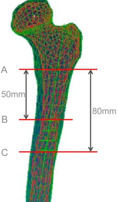
21)was also used to determine the femoral axis. More specifically, the femoral axis was defined as a line connecting the center of cross-sec- tions at distances of 50 mm and 80 mm from the lesser tro- chanter (Figure 2b). The position of the lesser trochanter was the tip in the 3D model. Cross-sections including the femoral axis and femoral head center were created (Figure 2c).
Figure 1. Flow chart of measurements
The acquired CT DICOM data were input into Mimics to create a 3D model, surface smoothing was performed using Geomagic Studio, and this was input into Unigraphics CAD software for measurements.
CT scan 3D model Smoothing and
files convert to IGES
Unigraphics Measurement
DICOM data Mimics Geomagic Studio
Figure 1
CAD
50mm
80mm A
B C
Figure 2b Figure 2a
Figure 2. Measurement procedure
Figure 2a. An approximate sphere is created from three arbitrary cross-sections of the femoral head, and the center is defined as the femoral head center.
50mm
80mm A
B C
Figure 2b Figure 2a
Figure 2b. The tip of the lesser trochanter (A) is identified on the 3D model. The femoral axis is defined as a line connecting the center of cross-sections at distances of 50 mm (B) and 80 mm (C) from the lesser trochanter tip.
Lines at angles of 125°, 130°, and 135° from the femoral head center to the femoral axis were drawn on each cross- section (Figure 2d). Two circles (circle C and D) were drawn to approximate the inside of the inferior and the superior cor- tex of the femoral neck, and lines parallel to the line created in figure 2d were drawn at locations as tangent lines to the circle C and D. The distance between these two parallel lines was defined as the femoral neck isthmus space (FNIS) (Fig- ure 2e). The angle formed by the line connecting the femoral axis and femoral head center was defined as the femoral
neck-shaft angle. Anteversion was the angle made with cross-section of figure 2d (the section include femoral head center and femoral axis) and line drawn between the medial and lateral epicondyle of distal femur as described by Mur- phy et al.
22). Medial and lateral epicondyle was identified as the tip in the 3D model.
In addition, anterior and posterior sections that included the neck axis, making an angle of 130° with the femoral axis, including the femoral head center, were created. On these cross-sections which was a shape of cancellous bone, circles
Figure 2c Figure 2d
Femoral shaft Center of
femoral head
Figure 2e
FNIS
Circle C
Circle D
Figure 2c Figure 2d
Femoral shaft Center of
femoral head
Figure 2e
FNIS
Circle C
Circle D
Figure 2c Figure 2d
Femoral shaft Center of
femoral head
Figure 2e
FNIS
Circle C
Circle D
Figure 2c. A cross-section including the femoral axis and femoral head center is cre- ated.
Figure 2d. Lines at angles of 125°, 130°, and 135° from the femoral axis to the femo- ral head center are drawn.
Figure 2e. Circles C and D adjacent superi- orly and inferiorly to the femoral neck are created. Lines parallel to the line created in Fig. 3b are drawn at locations as tangent lines to the circles. The distance between these two parallel lines is defined as the FNIS.
Circle E
A‐P diameter
Circle F
Figure 2f
Figure 2f. For measurements on the lateral view, cross-sections including the femoral head center and making a 130° angle with the femoral axis are created.
Circles E and F adjacent anteriorly and posteriorly to the femoral neck are created. Lines tangent to circles E and F and parallel to the line drawn from the femoral axis to the femoral head center are drawn. The distance between the two parallel lines is defined as the femoral neck A-P diameter.
E and F adjacent anteriorly and posteriorly to the femoral neck were created. The distance between the two tangent points with the femoral neck was defined as the femoral neck A-P diameter on the lateral view (Figure 2f). Moreover, fem- oral head diameter, version, neck shaft angle, offset of the femoral head center from the femoral axis, and femoral length were measured using CAD software. They were mea- sured up to thrid decimal place and rounded to first decimal place. Statistical analysis was performed using the non- paired t-test. Each data of FNIS and femoral neck A-P diam- eter on the lateral view was expressed as mean (minimum- maximum).
Results
Mean age was 37.1 years in the N group and 38.7 years in the DH group. The mean CE angle was 36.2±6.5° in the N group and 24.7±16.8° in the DH group (p<0.05), and the
mean Sharp angle was 39.8±4.4° in the N group and 46.1±3.0° in the DH group (p<0.01). The mean femoral head diameter was 42.6±3.6 mm in the N group and 45.2±4.1 mm in the DH group (p<0.05). The mean antever- sion angle was 32.1±9.5° in the N group and 36.4±11.4° in the DH group (p=0.21). The mean femoral neck-shaft angle was 129.7±5.4° in the N group and 132.3±8.9° in the DH group (p =0.249). The mean offset of the femoral head cen- ter from the femoral axis was 39.5±4.0 mm in the N group and 33.6±4.3 mm in the DH group (p <0.01) (Table 1).
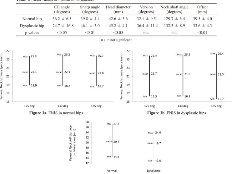
The mean FNIS in the N group was 22.1 mm (18.9-25.8 mm) at an angle of 125°, 22.1 mm (18.8-26.2 mm) at an angle of 130°, and 21.8 mm (18.7-25.9 mm) at an angle of 135° (Figure 3a). The mean FNIS in the DH group was 21.7 mm (16.3-25.9 mm) at an angle of 125°, 21.6 mm (16.3-26.2 mm) at an angle of 130°, and 21.5 mm (15.7-26.4 mm) at an angle of 135° (Figure 3b). The femoral neck A-P diameter on the lateral view was 20.4 mm (14.5-27.3 mm) in the N group and 19.7 mm (13.0-24.0 mm) in the DH group (Figure 3c).
Table 1. Mean values of measured parameters CE angle
(degrees) Sharp angle
(degrees) Head diameter
(mm) Version
(degrees) Neck shaft angle
(degrees) Offset (mm) Normal hip 36.2 ± 6.5 39.8 ± 4.4 42.6 ± 3.6 32.1 ± 9.5 129.7 ± 5.4 39.5 ± 4.0 Dysplastic hip 24.7 ± 16.8 46.1 ± 3.0 45.2 ± 4.1 36.4 ± 11.4 132.3 ± 8.9 33.6 ± 4.3
p values <0.05 <0.01 <0.05 n.s. n.s. <0.01
n.s. = not significant
18.9 18.8 18.7
22.1 22.1 21.8
25.8 26.2 25.9
15 17 19 21 23 25 27
125 deg 130 deg 135 deg
Figure 3a
Femoral Neck Isthmus Space (mm) Max
mean
Min Max
mean
Min Max
mean
Min
16.3 16.3
15.7
21.7 21.6 21.5
25.9 26.2 26.4
15 17 19 21 23 25 27
125 deg 130 deg 135 deg
Figure 3b
Femoral Neck Isthmus Space (mm) Max
mean
Min Max
mean
Min Max
mean
Min
Figure 3a. FNIS in normal hips Figure 3b. FNIS in dysplastic hips
Figure 3c Femoral Neck A‐P diameter on lateral view (mm)
14.5
13.0
20.4 19.7
27.3
24.0
12 14 16 18 20 22 24 26
28 Max
mean
Min
Normal Dysplastic
Max
mean
Min
Figure 3c. Femoral neck A-P diameter on the lateral view
There were no significant differences in FNIS or femoral neck A-P diameter based on the presence or absence of hip dysplasia.
Discussion
Measurements of proximal femur morphology using CT have previously been reported
17),18),23),24)(Table 2). Argenson et al.
18)and Sugano et al.
17)compared hips with no or few morphological abnormalities and dysplastic hips, and as they reported, the present study also found more anteversion in dysplastic hips. However, the differences were not signifi- cantly different in our study. In addition, as reported by Ar- genson et al.
18), offset was significantly decreased in dys- plastic hips compared to primary osteoarthritic hips.
Although the measurement methodology differed in each study, the present results were similar to those of previous reports.
Early osteosynthesis is recommended for proximal femur fractures
9),10). Treatment includes the use of sliding hip screws and short femoral nails
12). Baumgartner et al.
25)re- ported that insertion of lag screws towards the femoral head center can decrease the rate of cut-out, the most common cause of postoperative failure. The diameter of implant lag screws currently used in Japan ranges from 10.3 mm to 15.3 mm (Table 3). The present study showed that these lag screws are suitable over an FNIS range and can be inserted
at ideal positions described by Baumgartner. It also showed that A-P diameter on the lateral view was large enough.
However, the smallest FNIS values in the DH group were : 16.3 mm at 125°, 16.3 mm at 130°, and 15.7 mm at 135°.
Therefore, caution is necessary to avoid bone perforation during the lag screw insertion.
For basicervical fractures of the femur, in addition to a sliding hip screw, one screw to control rotation is recom- mended
26),27).A 6.5-mm, cannulated cancellous screw is generally used to control rotation durinig the operation. Lag screws with a diameter of about 12 mm are used as sliding hip screws. Thus, the size of both together is about 20 mm, but according to the present study, these may not fit within the FNIS in some patients specially those who have dysplas- tic hip. The main purpose of the cancellous screw is not to increase postoperative fixation, but rather to control rotation during lag screw insertion. Therefore, in patients in whom the FNIS is expected to be smaller, the use of a smaller, can- nulated cancellous screw should be considered.
In conclusion, this is the first study to analyze the medul- lary morphology of the proximal femur in Japanese women using CT data. The present findings suggest some risk of bone perforation, especially in dysplastic hips, with internal fixation devices that are currently used. The present study findings may be very useful when developing hip prostheses that are more suitable for Asian patients and when develop- ing new lag screws to improve treatment outcomes in proxi- mal femur fracture.
Table 2. Mean values of parameters measured in literature
Study Hip anatomy Version
(degrees) Neck shaft angle
(degrees) Offset
(mm) Noble
Argenson Sariali Sugano Our study
Primary OA Primary OA Primary OA Normal hip Normal hip
24.7 ± 8.7 ND 21.9 ± 9.4 22.6 ± 10.6 32.1 ± 9.5
124.7 ± 7.4 129.2 ± 7.8 129.5 ± 5.5 125.8 ± 6.3 129.7 ± 5.4
43.0 ± 6.8 40.5 ± 0.4 42.2 ± 5.1 39.5 ± 4.0ND
Argenson Sugano Our study
Dysplastic hip Dysplastic hip Dysplastic hip
31.1 ± 1.8 34.0 ± 16.0 36.4 ± 11.4
130.3 ± 1.2 127.9 ± 8.9 132.3 ± 8.9
25.7 ± 1.7 33.6 ± 4.3ND
OA = osteoarthritis; ND = not determined
Table 3. Size of the lag screws sold in Japanese market
Trade name Company Diameter (mm)
Gamma nailPFNA IMHSITST Ω Hip screw
Inter TANDHS
DePuy Synthes Striker Smith & Nephew
Zimmer Striker DePuy Synthes Smith & Nephew
10.310.5 11.011.0 12.012.5 15.3
Acknowledgments
Data analysis was partialy supported by Mr. Masataka Endo, and author thank him for his kindness.
Conflict of interest statement
The authors have no conflicts of interest to disclose.
References
1. Committee for Osteoporosis Treatment of The Japanese Orthopaedic A. Nationwide survey of hip fractures in Japan. J Orthop Sci 9(1):1-5, 2. Hagino H, Furukawa K, Fujiwara S, et al. Recent trends in the inci-2004
dence and lifetime risk of hip fracture in Tottori, Japan. Osteoporos Int 20(4): 543-548, 2009
3. Orimo H, Yaegashi Y, Onoda T, Fukushima Y, Hosoi T, Sakata K. Hip fracture incidence in Japan: estimates of new patients in 2007 and 20- year trends. Arch Osteoporos 4(1-2): 71-77, 2009
4. Jaglal SB, Weller I, Mamdani M, et al. Population trends in BMD test- ing, treatment, and hip and wrist fracture rates: are the hip fracture projections wrong? J Bone Mineral Res 20(6): 898-905, 2005 5. Kannus P, Niemi S, Parkkari J, Palvanen M, Vuori I, Jarvinen M. Na-
tionwide decline in incidence of hip fracture. J Bone Mineral Res 21(12): 1836-1838, 2006
6. Chevalley T, Guilley E, Herrmann FR, Hoffmeyer P, Rapin CH, Riz- zoli R. Incidence of hip fracture over a 10-year period (1991-2000):
reversal of a secular trend. Bone 40(5): 1284-1289, 2007
7. Amin S, Achenbach SJ, Atkinson EJ, Khosla S, Melton LJ, 3rd. Trends in fracture incidence: A population-based study over 20 years. J Bone Mineral Res : Aug 19 2013.
8. Lakstein D, Hendel D, Haimovich Y, Feldbrin Z. Changes in the pat- tern of fractures of the hip in patients 60 years of age and older be- tween 2001 and 2010: A radiological review. Bone Joint J 95-B(9):
1250-1254, 2013
9. Zuckerman JD, Skovron ML, Koval KJ, Aharonoff G, Frankel VH.
Postoperative complications and mortality associated with operative delay in older patients who have a fracture of the hip. J Bone Joint Surg Am 77(10): 1551-1556, 1995
10. Moran CG, Wenn RT, Sikand M, Taylor AM. Early mortality after hip fracture: is delay before surgery important? J Bone Joint Surg Am 87(3): 483-489, 2005
11. Hill CE, Shapey IM, Eales F, McKloskey G, Costa ML. Theatre with- in 36 h for patients with fracture of the proximal femur: can we de-
liver? Arch Orthop Trauma Surg 133(3): 367-371, 2013
12. Anglen JO, Weinstein JN, American Board of Orthopaedic Surgery Research C. Nail or plate fixation of intertrochanteric hip fractures:
changing pattern of practice. A review of the American Board of Or- thopaedic Surgery Database. J Bone Joint Surg Am 90(4): 700-707, 13. Huang X, Leung F, Xiang Z, et al. Proximal femoral nail versus dy-2008
namic hip screw fixation for trochanteric fractures: a meta-analysis of randomized controlled trials. Sci World J 805805, 2013
14. Zhang F, Tan LJ, Lei SF, Deng HW. The differences of femoral neck geometric parameters: effects of age, gender and race. Osteoporos Int 21(7): 1205-1214, 2010
15. Tyagi V, Yang JH, Oh KJ. A computed tomography-based analysis of proximal femoral geometry for lateral impingement with two types of proximal femoral nail anterotation in subtrochanteric fractures. Injury 41(8): 857-861,2010
16. Clohisy JC, Nunley RM, Carlisle JC, Schoenecker PL. Incidence and characteristics of femoral deformities in the dysplastic hip. Clin Or- thop 467: 128-134, 2009
17. Sugano N, Noble PC, Kamaric E, Salama JK, Ochi T, Tullos HS. The morphology of the femur in developmental dysplasia of the hip. J Bone Joint Surg Br 80(4): 711-719, 1998
18. Argenson JN, Flecher X, Parratte S, Aubaniac JM. Anatomy of the dysplastic hip and consequences for total hip arthroplasty. Clin Or- thop 465: 40-45, 2007
19. Nakamura S, Ninomiya S, Nakamura T. Primary osteoarthritis of the hip joint in Japan. Clin Orthop 241 : 190-196, 1989
20. Lamvohee JM, Mootanah R, Ingle P, Cheah K, Dowell JK. Stresses in cement mantles of hip replacements: effect of femoral implant sizes, body mass index and bone quality. Comput Methods Biomech Biomed Engin 12(5):501-510, 2009
21. Noble PC, Kamaric E, Sugano N, et al. Three-dimensional shape of the dysplastic femur: implications for THR. Clin Orthop 417: 27-40, 22. Murphy SB, Simon SR, Kijewski PK, Wilkinson RH, Griscom NT. 2003
Femoral anteversion. J Bone Joint Surg Am 69(8):1169-1176, 1987 23. Noble PC, Alexander JW, Lindahl LJ, Yew DT, Granberry WM, Tul-
los HS. The anatomic basis of femoral component design. Clin Orthop 235: 148-165,1988
24. Sariali E, Mouttet A, Pasquier G, Durante E. Three-dimensional hip anatomy in osteoarthritis. Analysis of the femoral offset. J Arthro- plasty 24(6): 990-997, 2009
25. Baumgaertner MR, Solberg BD. Awareness of tip-apex distance re- duces failure of fixation of trochanteric fractures of the hip. J Bone Joint Surg Br 79(6): 969-971,1997
26. Blair B, Koval KJ, Kummer F, Zuckerman JD. Basicervical fractures of the proximal femur. A biomechanical study of 3 internal fixation techniques. Clin Orthop 306: 256-263,1994
27. Bray TJ. Femoral neck fracture fixation. Clinical decision making.
Clin Orthop 339:20-31,1997