CHARACTERISTICS OF 3D STEEL
SUBASSEMBLAGES WITH STEEL RHS COLUMN AND WIDE FLANGE BEAM STIFFENED
BY EXTERNAL DIAPHRAGM UNDER BIAXIAL LATERAL FORCE
SUI WeiNing1 and YAMANARI Minoru2
1Graduate School of Science and Technology, Kumamoto University
2Department of Architecture, Faculty of Engineering, Kumamoto University 2-39-1, Kurokami, Kumamoto 860-8555 Japan
ABSTRACT
This paper describes about elastic-plastic characteristics of steel frames, which are made of rectangular hollow section columns and wide flange beams connected with external diaphragms. There are a lot of studies have been done with a planar frame method, and many important data have been concluded from it. But in fact, the structure is a three-dimensional frame. In order to know the data of the frame character- istics and use it to have design, the information only by planar frame’s analysis is not enough, It is important to have a study with three dimensions method. In the other paper, a study about circular col- umns and wide flange beams had been studied with three dimensions method. Here, a study of subassem- blages with RHS columns was also done with three dimensional methods. The external force is a biaxial laternal force, and the local deformation is generated at two directions’ flanges.
KEYWORDS
Rectangular hollow steel column, beam-to-column connection, external diaphragm, biaxial lateral force, finite element analysis, three-dimensional method
1. INTRODUCTION
In this paper, a study is introduced about subassemblages’ analysis result which is made of rectangular hollow section columns and wide flange beams connected with external diaphragms. The study is done with Finite Element Analysis (FEA) program and is based on three-dimensional analysis methods. It is different from planar frame analysis method. As known the external force , such as seismic, wind force, blast act on the frame from an arbitrary direction. The direction of the external force did not known before they are happened. With three dimensional theory, the analysis model is similar to the real struc- tures, and the reliability is higher. So it is superiority in designing of frame. A study about a subassem- blages which is made of circular hollow columns and wide flange beams is introduced in the other papers
1000
1000 1000 1000
(mm) 750
750
XXR Frame
1000
1000 750 1000
750
(mm) TXR Frame
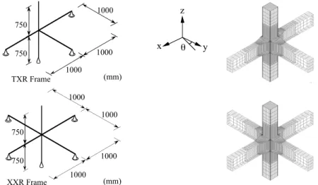
Figure 1: Boundary Conditions and Finite Element Analysis Models
(Refs, [1], [2]), and it is known that the change of the force’s direction does not have clearly influence on the characteristics of the frame. The frame with CHS column and wide flange beam is an anisotropy frame, the characteistics of the panel zone did not change with the force’s direction. However the effec- tive plastic modulus of the frame’s panel zone which used in here is changed with the change of the force’s direction. So it is necessary to have a study of the subassemblages’ characteristics with the change of the external force direction.
2. FINITE ELEMENT ANALYSIS RESULTS OF 3D STEEL SUBASSEMBLAGE UNDER BI- AXIAL HORIZONTAL FORCES
There were two kinds of 3D space subassemblages shown in Figure 1, and the models are named as TXR Frame and XXR Frame. TXR Frame is partial frame of side column and XXR Frame is partial frame of middle column. T and X is the form of the part frame looked from the axis of columns, and they are named as TXR Frame and XXR Frame. The boundary condition of each analysis model is also shown in Figure 2. As the subassemblages is drawn from a frame by cutting the frame in the middle of the beams and columns, the beams and columns are continuous members, the twist in the axis direction of the beam is restricted. And the boundary condition is roller support. The column’s boundary conditions same with the beams boundary conditions, in order to prevent the rigid moving, the boundary conditions of the frame’s bottom were restricted, the external force is a biaxial force applied on the top of the column. A series of analysis was done with the finite element analysis program in computer.
3. RESULTS OF ANALYSES 3.1 Load-deformation curves
The analysis results of the side column part frames (TXR Frame) about the relationship of load-deforma- tion are shown in Figure 2. Angle (θ) is the angle between lateral load’s direction and y axies direction.
The coordinate system is shown in Figure 1. With the increase of the angle (θ), the gradation of load- deformation curves is increasing. Because with the increase of the angle, the shape of the frame was changed from T shape to X shape. When the angle is changed from 0 degree to 45 degree, the change of curve is sharply. Between 60 degree and 90 degree, the change of curve is smaller. The analysis result of the middle column part frames (XXR Frame) are shown in Figure 3. XXR Frame is different from TXR Frame, it is a symmetrical frame. The results from 0 degree to 45 degree is same to the results between 45 degree to 90 degree. From the graphs of the relationship of load-deformation, it can be seen when the increase of the external force’s angle is changed from 0 degree to 45 degree, the strength is raised after the yield of the frame. Although the initial stiffness is invariable. Because the effective plastic modulus of the rectangular hollow section is changed with the force’s direction, then when the angle is increased the local deformation and local buckling is generated easier than before.
x θ y
z
Figure 2: FE Analysis Results of TXR Frame Figure 3: FE Analysis Results of XXR Frame 3.2 Initial stiffness
In Figure 2 and Figure 3, initial stiffness of TXR Frame is changed with the the external force’s direction.
However, that of XXR Frame is unchanged with the external force’s direction. Here, with structural mechanics method, the initial stiffness of TXR Frame when θ is 0 degree is calculated (Ref. [2]), and the process is wrote in below:
When the deformation of the frame is generated only by the deform of the beams, the stiffness (KB ) of the frame (only relate to the stiffness of beams) can be written as
KB= l 4h2
L2 3EIB
+ κB
GAB – 1
(1) When the deformation of the frame is generated only by the deformation of the columns, the stiffness(KC ) of the frame (only relate to the stiffness of columns) can be written as
KC = 1 2H
H2 3EIC+ κC
GAC
–1
(2) When the deformation of the frame is generated only by the deformation of the panel zone, the stiff- ness(KP ) of the frame (only relate to the stiffness of panel zone) can be written as
KP = 1κCGAC
DBl 2L+DC
4LH–DBDC 2hL–DBl (3) When the deformation of the frame is generated only by the deformation of beam and column connec- tions, the stiffness (KL) of the frame (only relate with the stiffness of beam and column connections) can be written as
KL = Krl
4HhL (4) With the stiffness relate to the deformation of the frame’s members, the initial stiffness of the frame (K) can be calculated, the equations can be written as
K= 1 KB
+ 1KC
+ 1KP
+ 1KL – 1
(5) where E is Young’s modulus, Gis shear modulus, l is the length of beams and h is the heigth of columns which is shown in Figure 1, DB is the heigth of the panel zone, DC is the length of panel zone, L= l–DC/ 2
and H= h–DB/ 2 , κB and κC is the shape factor of beams and columns’ cross section relate to shear. IB
and IC are the moment of inertia of area of beams and columns, AB and AC is the sectional area of beams
0 50 100 150
0 50 100 150 200 250
θ= 0, 90deg 15, 75deg 30, 60deg 45deg
Deformation δ (mm)
Load P (kN)
0 50 100 150
0 50 100 150 200 250
Deformation δ (mm)
Load P (kN)
θ= 0 deg 15 deg 30 deg 45 deg 60 deg 90 deg
0 20 40 60 80 100
0 15 30 45 60 75 90
General yield load P (kN)y
θ(deg) Angle
TXR Frame
0 20 40 60 80 100
0 15 30 45 60 75 90
General yield load P (kN)y
θ(deg) Angle
XXR Frame
Figure 5: General yeld load of TXR Frame and XXR Frame Figure 6: Definition of General Yield Load
General yield load of TXR Frame and XXR Frame is shown in Figure 5. It is gotten From the analysis results of the frame about load-deformation relationship.The general yield load here is defined as the strength of the frame when the stiffness of the frame is decreased to 1/3 of the initial stiffness. And it is expressed as the graph which is shown in Figure 6. In TXR Frame, with the increase of the angle, the general yield load is increased. When the angle is over 45 degree, the increase of the general yield load get smaller. In XXR Frame the change of the general yield load is smaller. when the angle reached to 45 degree, the maxium general yield load result is got.
4. THE ANALYSIS RESULTS OF THE FRAME WITH ONE DIRECTION’S BEAM OFF- CEN- TER ARRANGED
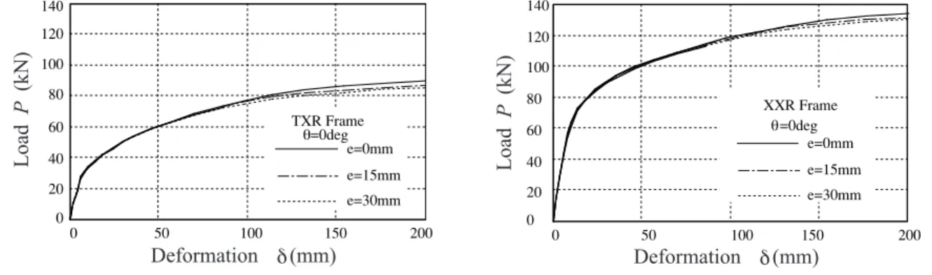
When the frame with y direction’s beam tranfered from the center line, the frame become an asymmetri- cal frame. The distance between the center line of the frame and the center line of the off-center arranged beam is 15mm and 30mm. The analysis result is drawn in Figure 7. Only the analysis result of TXR Frame and XXR Frame when the angle θ is 0 degree is drawn in here. In Figure 7, it can be seen that with the off center arrange of the beam, the influence on the frame’ behavior is rather smaller. In fact, even with the change of the external force’s direction, the effect on the characteristics of the asymmetrical and columns. Kr is the stiffness of rotational spring which represents a beam-column connection (Ref.
[3]).
The calculation with equation (7) is written in Figure 4 in break line, in Figure 4, the solid line is the analysis result, and the dot line is the calculation of the frame’s initial stiffness which ignored the influ- ence of the panel and beam-column connections. The initial stiffness of the frame based on structural mechanics is decreased about 5% of FEM analysis result when all the members’ deformation of the frame is thought. And it can be said the result of two theories method traced each other. When the analysis only thought about the deformation of beams and columns and the stiffness of panel zone and beam-column connections is ignored, the initial stiffness of the frame based on structural mechanics is increased about 25% of FEM analysis result. Here the influence of the frame’s connect section on the initial stiffness of the frame can be seen easily.
3.3 General yield load
Figure 4: Initial stiffness of different manner of calculation
0 10 20 30 40 50
0 2 4 6 8 10
Load P (kN)
Deformation (mm)δ
1 K /3E
1 KE Py
P
δ
5 FRAMES WITH TWO DIRECTION BEAMS WITH DIFFERENT HEIGHT
Another reason can let frames become an asymmetrical frame. It is when the height of two direction’s beams is different. And it is usual of the two direction’s beams with different height in fact. Here, the characteristic of it under a biaxial external force is studied. The upper flange of the two directions’ beams are on a surface. The lower flange of the shallower beam is connected to column with external diaphragm which is cut near the other direction’s web of beams.
The characteristics of the frame when the external force’s direction is 0 degree and 45 degree is studied in here. Parameter r is used to express the difference of two direction beams’ height. And r is defined as the proportion of y direction’s beam height and x direction’s beam height. And the height of x direction’s beam is fixed here. The value used in here is when r=1,0.75,0.5. The analysis result is write from Figure 8 to Figure 10. When the angle (θ) is 0 degree, the change of r have a clearly influence on the character- istics of the frame. When the angle (θ) is 45 degree, the influence is smaller. The influence by the changed of r is indistinct. It is said when the angle is 0 degree, the external force is main resisted by y direction’s beams. And when the angle is 45 degree , x direction’s beam together with y direction’s beam resist the external force, and the action of x direction’s beam is distinct. It can be said that the change of the ratio r,
Figure 8: Analysis Result (TXR Frame)
Figure 10: Analysis Result (XXR Frame)
Figure 9: Analysis Result (TXR Frame)
Figure 11: Analysis Result (XXR Frame)
0 50 100 150 200
0 20 40 60 80 100 120 140
r=1 r=0.75 r=0.5 XXR Frame
θ=0deg
0 50 100 150 200
0 20 40 60 80 100 120 140
r=1 r=0.75 r=0.5 XXR Frame
θ=45deg
0 50 100 150 200
0 20 40 60 80 100
120 r=1
r=0.75 r=0.5
TXR Frame θ=0deg 140
0 50 100 150 200
0 20 40 60 80 100 120 140
r=1 r=0.75 r=0.5 TXR Frame
θ=45deg
Figure 7: The Influence of the frame with off-center arranged beam
Load P (kN)
Deformation (mm)δ
Load P (kN)
Deformation (mm)δ
Load P (kN)
Deformation (mm)δ
Load P (kN)
Deformation (mm)δ
0 50 100 150 200
0 20 40 60 80 100 120 140
e=0mm e=15mm e=30mm XXR Frame
θ=0deg e=0mm
e=15mm e=30mm TXR Frame
θ=0deg
0 50 100 150 200
0 20 40 60 80 100 120 140
Load P (kN)
Deformation (mm)δ
Load P (kN)
Deformation (mm)δ
frame is within 3%. The influence of the off-center frame can be ignored in the prequalification data here.
0 20 40 60 80 100
0 15 30 45 60 75 90
General yield load P (kN)y
θ(deg) Angle
r=1 r=0.5 TXR Frame θ=45deg
Figure 12: The analysis result of general yield load 6 CONCLUSIONS
From the analysis result of frame in this study, the conclusion can be obtained as below:
(1) The change of the external force’s direction did not have clearly influence on the characteristic of the subassemblages that is made of steel rectangular hollow section columns and steel wide flange beams connected with external diaphragms. The analysis of subassemblages under biaxial lateral force have same conclusion with the study with planar frame analysis method. It is said it is enough to have a design with planar frame design method.
(2)The conclusion in (1) is based on the analysis of symmetrical subassemblages. The conclusion can be understood easily that the direction of the external force did not have influence on the symmetical frame.
During the analysis of the frame with off-center arranged beams and different beam’s section in two direction of the subassemblages, the change of the external force’s direction have a conspicuous influ- ence on the subassemblages.
References
[1]Sui W. and Yamanari M. (2004) A Study on Elasto-Plastic Characteristics of 3D Space Steel Subassamblage with CHS Column and Wide Flange Beam under Biaxial Loadings, Journal of Construc- tional Steel, Vol.12, pp.261-268, 2004.11 ( in japanese)
[2]Yamanari M., Ogawa K. and Kurobane Y. (1994) Inelastic Behavior of Semi-Rigid Corner Connec- tions with RHS Column and Wide Flange Beam, Journal of Structural Engineering, Vol.40B, pp.703-710 (in japanese)
[3]Yamanari M., Ogawa K., Kurobane Y. and Hiroyuki K. (1992) Evaluation of Rigidity of Connections with External Diaphragms Derived from FE Analysis (Study on Restoring Characteristics of Semi-Rigid Steel Beam-to Column connections), Journal of Structural Engineering, Vol.38B, pp. 475-484
and the change of the external force’s derection of a frame with different beam height in two direction have a clearly influence on the characteristics of the frame. In Figure 9 and Figure 11, the local buckling and local deformation of r=0.75 and r=0.5 is happened uneasily than r=1 frame. The frame with differ- ence height of the two directions’ beams is good for the disperse of the stress on the connection of the beam’s pull side flange. In Figure 9, when the external force’s direction is 45 degree, the analysis result is similar even with the change of the ratio r. In order to know the influence of the external force’s direction, a study is done of a frame with ratio r=0.5. The external force’s direction (θ) is range by 5 degree between 0 degree and 90 degree. The characteristic of the frame about general yield load is showed in Figure 12. When the external force’s angle is reached to 30 degree, the raise of general yield load is stopped, and the value keeps constant. After 30deg, the analysis of r=0.5 is same to r=1. It is said that the characteristics of the frame with two direction beams have difference height is changed clearly with the change of the external force’s direction. And the influence can not be ignored during the design of the frame.