Development of Triangular Microstrip Antenna for Sensor Application Using Circularly
Polarized‑Synthetic Aperture Radar
著者 ムハマド ファウザン エディ プルノモ
著者別表示 Muhammad Fauzan Edy Purnomo journal or
publication title
博士論文要旨Abstract 学位授与番号 13301甲第4830号
学位名 博士(工学)
学位授与年月日 2018‑09‑26
URL http://hdl.handle.net/2297/00053077
doi: 10.11113/jt.v80.11119
Dissertation Abstract
Development of Triangular Microstrip Antenna for Sensor Application Using
Circularly Polarized-Synthetic Aperture Radar
円偏波合成開口レーダを用いたセンサ応用のための正三角形 マイクロストリップアンテナの開発
Graduate School of
Natural Science and Technology Kanazawa University
Division of Electrical Engineering and Computer Science
Student ID No.: 1624042014
Name: Muhammad Fauzan Edy Purnomo Chief advisor: Prof. Akio Kitagawa
Date of submission: June 28, 2018
Abstract
Recently, many missions of Synthetic Aperture Radar (SAR) sensors are operated in linear polarization (HH, VV, and its combination) with high power, sensitive to Faraday rotation effect, etc.
Newly, the development of radar technology, SAR and Unmanned Aerial Vehicle (UAV) are relatively fast which can generate data processed with high resolution and a better image for all types of terrain explored. The interest in the SAR system is expected to increase the research about the antenna which can be applied for developing SAR system.
Circularly Polarized-Synthetic Aperture Radar (CP-SAR) is as active sensor that could transmit and receive the C, S, and L-band chirp pulses for remote sensing application. The sensor is designed as a low cost, light, low power, low profile configuration to transmit and receive Left-Handed Circular Polarization (LHCP) and Right-Handed Circular Polarization (RHCP). Then, these circularly polarized waves are employed to generate the Axial Ratio Image (ARI), ellipticity and tilted angle images, etc.
Hence, many information can be obtained from the earth and be able to overcome some limitations of the SAR sensor, such as high power, sensitive to Faraday rotation effect, the unwanted backscatter modulation signal and redistribution random back signal-energy, blurring and defocusing spatial variants, ambiguous identification, and low different features of backscatter.
In this research, we design triangular microstrip antennas both as basic construction and configuration of CP-SAR operated and embedded at the S-band and L-band on Low Earth Orbit (LEO) microsatellite and UAV having additional advantages such as a compact size, lightweight, conformability of the substrate surface, low cost, easier to integrate with other circuits, flexible, and well established. The investigation triangular microstrip antennas and its radiation characteristics are performed by numerical simulations and partly experiments aimed at CP-SAR sensor application.
The values of gain, axial ratio (Ar) and its bandwidth, azimuth and elevation beamwidth of gain and Ar, and antenna efficiency of triangular microstrip antennas are sufficient performances to meet the requirement of the specification of CP-SAR system using LEO microsatellite and UAV.
Keywords: CP-SAR, LHCP, RHCP, triangular microstrip antennas, LEO microsatellite, UAV 1. Introduction
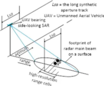
The two main types of radar images are the circularly scanning Plan-Position Indicator (PPI) images and the side-looking images. The PPI applications are limited to monitor the air and naval traffic.
The side-looking images applied in remote sensing are divided into two types: (i) Real Aperture Radar (RAR, usually called SLAR for Side-Looking Airborne Radar or SLR for Side-Looking Radar) (ii) Synthetic Aperture Radar (SAR).
The construction beam (Figure 1) tends to relatively tilted right toward UAV moving forward.
Hence, one of many techniques to adjust beam direction is to excite the higher mode, especially the TM
21. When the antenna only has one element, the dominant mode is a role as the bigger beam rather than the higher mode of this patch [1]. But, when the antenna consist of array elements using corporate feeding-line (see parts 3.2 and 3.3), the antenna act as the higher mode (TM
21) CP that has the angle between the peak beam-direction and broadside around 20° until 50° depending on the values of dielectric constant of the substrate [2]. This condition happens because the location of corporate feeding-line is appropriately below the radiating patches having the perturbation segment.
Figure 1. SAR configuration
In the Figure 1, the beam antenna is set to be perpendicular with the UAV path. Then, we can recognize that the range resolution is also perpendicular against the observation track and the azimuth resolution that will be parallel to the track. The range resolution for SAR is not different with common radar, and SAR technique gives no effect to this resolution. SAR only focus on making the azimuth resolution of a radar better than RAR.
In this research, the triangular microstrip antennas both as basic construction and configuration of CP-SAR application operated and embedded at the S-band and L-band on LEO microsatellite and UAV are investigated.
2. Approach of the research
In this research of microstrip antennas, the numerical simulation and partly to be confirmed with measurement in radio anechoic chamber are performed, then the results of them are discussed. One of the most common techniques for calculating the unknown current of the patch antenna is the Method of Moments (MoM). This method discretizes the integral into a matrix equation which can be solved. This discretization can be considered as dividing the antenna surface into a number of small elements. From the current distribution, the S-parameter, radiation pattern, and any other parameters of interest can be obtained.
The software used is Ensemble
TMversion 8 from Ansoft [3] for calculating the model of antennas: c1, c2, c3, c3s, and equilateral triangular, especially at the frequency around 2.5 GHz – 2.9 GHz as a basic construction of array antenna embedded on LEO (Low Earth Orbit) microsatellite for CP-SAR application. Among these models, the model of equilateral triangular antenna using dual feed type one is more appropriate to conduct a multi-polarization (LHCP = Left-Hand Circular Polarization and RHCP = Right-Hand Circular Polarization) array configuration. Because it is loaded with isolation parameter compared to probe feed. Then, we select the model of equilateral triangular with microstrip line dual feed type one to discuss rather than the model c1, c2, c3, and c3s. Also, we use the software of Computer Simulation Technology (CST) version 2016 from corporate company CST STUDIO SUITE [4] to simulate the triangular microstrip antenna at a resonant frequency, f = 1.25 GHz. It is lied on airspace and discussed two from three parts (a) LHCP and RHCP single patch antennas, (b) LHCP and RHCP modified lossless T-junction power divider 2 1, (c) LHCP and RHCP array two patches antennas using the modified lossless T-junction power divider 2 1, i.e., parts (b) and (c) as basic construction of array antenna embedded on UAV for CP-SAR application. Furthermore, the configuration of equilateral triangular array antennas designed with truncated-tip including radiating patches and corporate feeding-line with their parameters at the resonant frequency, f = 1.25 GHz are denoted and discussed one of three parts (i) LHCP and RHCP triangular array four patches antennas, (ii) LHCP and RHCP triangular array eight patches antennas, (iii) LHCP and RHCP triangular array sixteen patches antennas, i.e., part (iii) because if the targeted elevation beamwidth in range 3.57°– 31.02° at Table 1, only sixteen patches antenna for UAV can obtain it.
The parameter sizes of each patch are the same, namely the length of triangle side, a = 95.2311 mm and p = 101.38 mm, the length of perturbation segment, h = 7.64 mm and t = 1.5008 mm. The corporate feeding-line has two nodes (four patches), seven nodes (eight patches), fifteen nodes (sixteen patches) of T-junction having a function to distribute the current from the input port to output ports and to reach 2 2, 2 4, and 2 8 patches, respectively. The same length from input port to output ports are around 3.75λ or 610.5 mm (four patches), 5.25λ or 854.7 mm (eight patches), and 7.9λ or 1286.12 mm (sixteen patches).
For a symmetric corporate feeding-line that the number of radiating patches is 2
mwith some requirements.
(i) m is an integer indicating the number of T-junctions toward patches for one patch, two and four patches.
(ii) While for eight patches, m is an integer denoting the number of T-junctions which are not through patches. (iii) For sixteen, thirty-two, sixty-four, one hundred and twenty-eight, etc. patches, m is an integer exhibiting the number of T-junctions which are not through patches and input port divided by two and added with one.
To obtain the triangular array antenna operating TM
21CP, we use the following rules [5, 6]: (i) The truncated-tip radiating patches cooperated with corporate feeding-line have proper setting size, (ii) Right-angle bend and T-junctions connected with the corporate feeding-line have lossless transmission, (iii) The element spacing of adjacent radiating patches is around λ/2, (iv) In order to preserve the symmetric beam and to keep the low CP and the higher gain, the unwanted beams need to be suppressed.
One of the major steps in designing of microstrip patch antenna is to choose a suitable dielectric
constant with appropriate thickness and loss tangent. A thicker substrate will increase the radiation power,
reduce conductor loss, and improve impedance bandwidth. A low value of the dielectric constant will increase the fringing field at the patch periphery. A high loss tangent rises dielectric loss and then reduces antenna efficiency. In this research, we choose the antenna substrate namely Nippon Pillar Packing (NPC) H220A which use a conventional substrate with dielectric constant or relative permittivity (ε
r) and loss tangent (δ) are 2.17 and 0.0005, respectively. Moreover, the substrate thickness of 1.62 (radiating patches and corporate feeding-line) is 3.2 mm. It is intended to attain the optimal performance of antenna characteristics that conform with a technical specification of CP-SAR system using the L-Band LEO microsatellite and UAV at Table 1 [7].
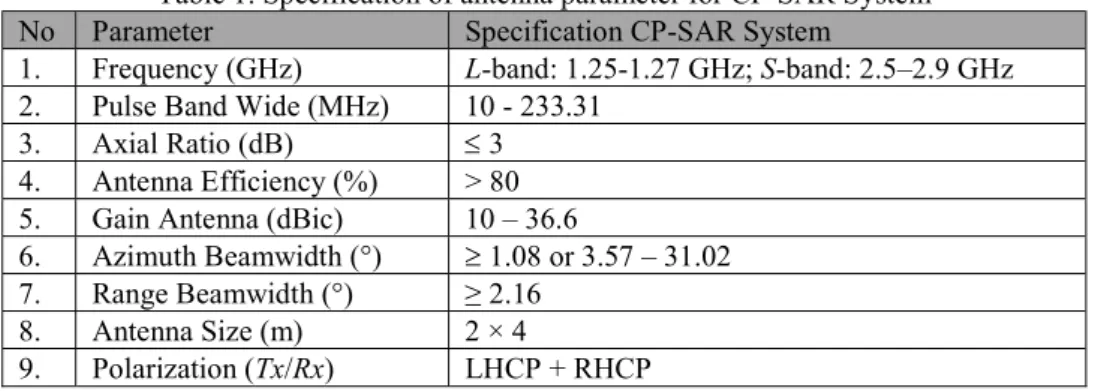
Table 1. Specification of antenna parameter for CP-SAR System
No Parameter Specification CP-SAR System
1. Frequency (GHz) L-band: 1.25-1.27 GHz; S-band: 2.5–2.9 GHz 2. Pulse Band Wide (MHz) 10 - 233.31
3. Axial Ratio (dB) 3
4. Antenna Efficiency (%) > 80 5. Gain Antenna (dBic) 10 – 36.6
6. Azimuth Beamwidth (°) 1.08 or 3.57 – 31.02 7. Range Beamwidth (°) ≥ 2.16
8. Antenna Size (m) 2 × 4
9. Polarization (Tx/Rx) LHCP + RHCP 3. Antennas configuration
3.1 Model equilateral triangular antenna
Figure 2 depicts the configuration of an optimized single equilateral triangular patch antenna with its fabrication and parameters. The patch antenna is fed by microstrip line to obtain a thin shape. The purpose of dual feed type one is to generate LHCP by using equilateral triangular patch antenna without truncated-tips, which one of the microstrip line feed is longer than the other to introduce a 90° phase delay.
The antenna is made of a thin conducting patch that the radiating patch and microstrip line feed is located on the same layer which has a thickness, h = 1.6 mm and uses a conventional substrate (ε
r= 2.17 and δ = 0.0009) [8].
Figure 2. Configuration of equilateral triangular antenna 3.2 Model equilateral triangular truncated-tip antenna
3.2.1 LHCP and RHCP modified lossless T-junction power divider 2 1 configuration
The power divider is a network with one input port and N output ports. The input power at the input port would be divided by the number of the output ports that yield the same output power at each output port. One common characteristic found in power dividers is reciprocity. A reciprocal device is the one in which the transmitted power between two ports of device is the same regardless of the propagation direction through the device. For a reciprocal device [9-11], we have
[𝑆] = [𝑆] 𝑜𝑟 𝑆 = 𝑆 ; 𝑓𝑜𝑟 𝑎𝑙𝑙 𝑖 𝑎𝑛𝑑 𝑗 (1)
Another property of the S-matrix is how much loss that can be attributed to the device. Ideally, a
lossless power divider would be used in a system. However, the only low-loss divider is physically
realizable. It has been shown, particularly by Pozar, that if the S-matrix of the device is unitary, then the device is lossless, as follow [9-11]
[𝑆] [𝑆]
∗= [𝐼] 𝑜𝑟 [𝑆
∗] [𝑆] = [𝐼] (2)
Where [I] is the identity matrix, the superscript T represents the transpose of the matrix, and the superscript asterisk (*) represents the conjugate of the matrix.
By the definition, a -3 dB power divider is an ideal passive lossless reciprocal three ports device that divides power equally in magnitude and phase (see Figure 3). The S-parameter matrix related to this device is
[𝑆] =
𝑆 𝑆 𝑆
𝑆 𝑆 𝑆
𝑆 𝑆 𝑆
(3)
According to the matrix in (3), the condition for a lossless network is given by equation (2). Also, the condition for a reciprocal network is described in equation (1). Then, the condition for coefficient reflection load (Γ
L) is
Γ = 1 − 𝑆 = ; 0 ≤ Γ ≤ 1; 𝑖, 𝑗 = 1,2,3 (4)
If Γ
L= 1⌊0°, then it occurs an open circuit condition. If Γ
L= 1⌊180°, this is a short circuit condition. If Γ
L= 0, then this is a matched load circuit condition. Since, all the three ports of this power divider are matched, S
ii= 0. The modified S-matrix for matched load condition is
[𝑆] =
0 𝑆 𝑆
𝑆 0 𝑆
𝑆 𝑆 0
(5)
In the S-matrix, the elements S
23and S
32are associated with the isolation between the output ports.
These correspond to signals entering port 2 and exiting port 3, and vice versa. When the magnitudes of these elements are small, high isolation is achieved between the ports. For the lossless condition to be true, the matrix in equation (5) must be unitary and satisfy
|𝑆 | + |𝑆 | = 1 (6)
|𝑆 | + |𝑆 | = 1 (7)
|𝑆 | + |𝑆 | = 1 (8)
𝑆
∗𝑆 = 0 (9)
𝑆
∗𝑆 = 0 (10)
𝑆
∗𝑆 = 0 (11)
This condition means that two of the elements S
12, S
13, and S
23must be equal to zero to satisfy equations (9) – (10). For the sake of clarity of this analysis, S
12and S
13set equal to zero. However, it is clear that by setting S
12and S
13equal to zero, equation (6) is not satisfied. Consequently, when two of the elements S
12, S
13, and S
23are equal to zero, one of the equations (6) – (8) will not be satisfied. Thus a matched, reciprocal, lossless of three ports network becomes impossible to be realized [9-11].
3.2.2 Configuration of LHCP and RHCP array antennas using power divider 2 × 1
Figure 3 shows the configuration of triangular array antenna both LHCP and RHCP include the two
radiating patches fed by corporate feeding-line with identical path lengths from the input port to output
ports and their parameters. The equilateral triangular patch has a length, a + t + h = p + 2t and a
conventional substrate, ε
r= 2.17 and δ = 0.0005. The parameter sizes of each patch (patch 1 and patch 2) are
the same, namely the length of triangle side, a = 95.2311 mm and p = 101.38 mm, the length of perturbation
segment, h = 7.64 mm and t = 1.5008 mm. Furthermore, the corporate feeding-line has one node of
T-junction. This node has a function to distribute the current and to reach 2 1 patches having the same
length from the input port to radiating patches or output ports around 9.32λ or 379.315 mm, where λ is
wavelength.
Figure 3. Configuration of LHCP and RHCP array antennas using power divider 2 1 3.3 Model LHCP and RHCP triangular array sixteen patches antennas
Figure 4 and Figure 5 show the configuration of triangular array antenna both LHCP and RHCP include the sixteen radiating elements/patches which are fed by 1:n (n is number of patches or n = 16) power divider network with identical path lengths from the input port to each patch or called corporate feeding-line, and their parameters [12, 13].
Figure 4. LHCP triangular array antenna 2 8 patches
Figure 5. RHCP triangular array antenna 2 8 patches
t t
t d
w2
h PATCH 2 w1
lfO
Δw1
q y
x
p PATCH 1
b
substrate
El x
O ground g2
z (side view)
Corporate feeding-line patch
v u c
substrate (top view)
Az
t d
w2 h
PATCH 2 w1 lf
O
Δw1 q y
x
p
PATCH 1 b
v u c
substrate (top view)
substrate
El x
O ground g2
z (side view)
Corporate feeding-line patch
Az
PORT 1 PORT 1
PORT 2 PORT 3
PORT 3 PORT 2
a
t
4. Results and discussion
4.1 Model equilateral triangular antenna
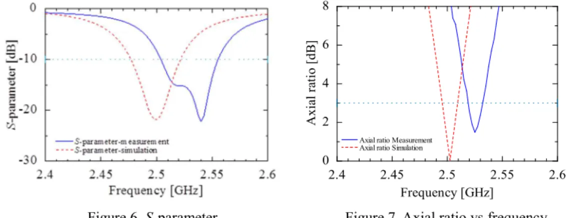
Figure 6 shows the relationship between the reflection coefficient (S-parameter) and frequency for simulation and measurement of Tx/Rx antenna. From this figure, it can be seen that by comparison of the measurement with the simulation there is a frequency shifting about 1.5%.
Figure 6. S-parameter Figure 7. Axial ratio vs frequency
Figure 7 shows that the value of axial ratio (Ar) measurement increases of about 18% compared to the simulation (0.27 dB to 1.49 dB), also the frequency is shifted about 0.9% (2.5 GHz shifts to 2.53 GHz).
Moreover, the bandwidth of axial ratio both simulation and measurement below 3 dB consecutive of about 0.02 GHz or 20 MHz and 0.015 GHz or 15 GHz meet for CP-SAR LEO microsatellite application.
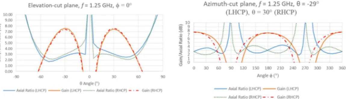
Figure 8 and Figure 9 depict the relationship between gain-axial ratio vs elevation (El) and gain-axial ratio vs azimuth (Az) in the area of El = 90° or θ = 0° at the resonant frequency, f = 2.5 GHz for simulation and f = 2.53 GHz for measurement. The 3-dB Ar-elevation beamwidth for simulation and measurement are successively about 120° and 80°. These values satisfy the targeted elevation beamwidth of
≥ 2.16° at Table 1. In addition, the values of the 3-dB Ar-azimuth beamwidth cover perfectly the whole of 360°. This result exhibit that the targeted azimuth beamwidth of ≥ 1.08° obtains the resolution of CP-SAR using LEO microsatellite.
Figure 8. Elevation-cut plane Figure 9. Azimuth-cut plane 4.2 Model equilateral triangular truncated-tip antenna
The real and imaginary parts of S-matrix both of LHCP and RHCP (Figure 3) of modified lossless T-junction power divider at f = 1.25 GHz taken from CST software are shown in equation (12) and (13), respectively.
[𝑆] =
0.04 + 𝑗0.16 0.44 − 𝑗0.53 0.43 − 𝑗0.54 0.44 − 𝑗0.53 −0.39 − 𝑗0.08 0.55 + 𝑗0.09 0.43 − 𝑗0.54 0.55 + 𝑗0.09 −0.38 − 𝑗0.07
(12)
We define that [𝑆] and [𝑆]
∗are transpose and a conjugate matrix of (12), respectively.
2.4 2.45 2.5 2.55 2.6
0 2 4 6 8
A xi al r at io [ dB ]
Axial ratio Measurement Axial ratio Simulation