Japan Advanced Institute of Science and Technology
JAIST Repository
https://dspace.jaist.ac.jp/Title
Performance of compact fast pyrolysis reactor
with Auger-type modules for the continuous liquid
biofuel production
Author(s)
Nishimura, Shun; Ebitani, Kohki
Citation
AIP Conference Proceedings, 1929(1):
020008-1-020008-9
Issue Date
2018-01-22
Type
Conference Paper
Text version
publisher
URL
http://hdl.handle.net/10119/15746
Rights
Copyright 2018 Authors. Published by AIP
Publishing. Shun Nishimura, Kohki Ebitani, AIP
Conference Proceedings, 1929(1), 020008 (2018)
and may be found at
http://dx.doi.org/10.1063/1.5021921
Description
Performance of compact fast pyrolysis reactor with
Auger-type modules for the continuous liquid biofuel production
Shun Nishimura
1),*and Kohki Ebitani
1)1Graduate School of Advanced Science and Technology,
Japan Advanced Institute of Science and Technology (JAIST), 1-1 Asahidai, Nomi, Ishikawa 923-1292, Japan
*Corresponding author: [email protected]
Abstract. Development of a compact fast pyrolysis reactor constructed using Auger-type technology to afford liquid
biofuel with high yield has been an interesting concept in support of local production for local consumption. To establish a widely useable module package, details of the performance of the developing compact module reactor were investigated. This study surveyed the properties of as-produced pyrolysis oil as a function of operation time, and clarified the recent performance of the developing compact fast pyrolysis reactor. Results show that after condensation in the scrubber collector, e.g. approx. 10 h for a 25 kg/h feedstock rate, static performance of pyrolysis oil with approximately 20 MJ/kg (4.8 kcal/g) calorific values were constantly obtained after an additional 14 h. The feeding speed of cedar chips strongly influenced the time for oil condensation process: i.e. 1.6 times higher feeding speed decreased the condensation period by half (approx. 5 h in the case of 40 kg/h). Increasing the reactor throughput capacity is an important goal for the next stage in the development of a compact fast pyrolysis reactor with Auger-type modules.
Keywords: Fast pyrolysis reactor, Auger-type module, Pyrolysis oil, Time-course performance
INTRODUCTION
Biomass utilization is expected to exert strong effects on the development of a sustainable society because related processes are based on reproducible resources and low impact for CO2 emissions with a carbon neutral
concept. Therefore, not only academic but also industrial researchers skilled in biology, catalysis, theoretical simulation, agriculture, and mechanical engineering have been pursuing highly efficient technologies for converting various biomass resources into valuable chemicals and fuels [1–6].
Fast pyrolysis of biomass resources is a unique methodology with high processing power in terms of biomass transformation. It affords three important biomass-derived materials: syngas (gas phase), pyrolysis oil (liquid phase), and biochar (solid phase) [7–9]. Among the developed reactors of various types, the fast pyrolysis reactor with Auger-type module(s) can support compact and high liquid yield processes effectively. As-produced pyrolysis oil and biochar are physically and chemically similar to materials obtained from conventional fast pyrolysis methods [9]. Because of this outstanding benefit of the Auger-type module, our project team has attempted to develop a new compact fast pyrolysis reactor for continuous liquid biofuel production [10]. We considered that such a compact and movable (in some cases) reactor can function in hilly and mountainous areas and wood treating companies to afford liquid biofuels that can be used to produce energy in rural areas. Such local production for local consumption in
Japan can provide benefits of reducing energy for transportation and can support environmentally friendly lifestyles for human society.
This report presents discussion of the recent performance of the developed compact fast pyrolysis reactor in our project based on the properties of as-produced pyrolysis oil as a function of operation time. We consider that this Auger-type modules reactor would be used at near places from such as a timber mill company and a pellet plant, serving a large quantity of woody biomass feedstock, constantly, as by-product.
EXPERIMENTAL
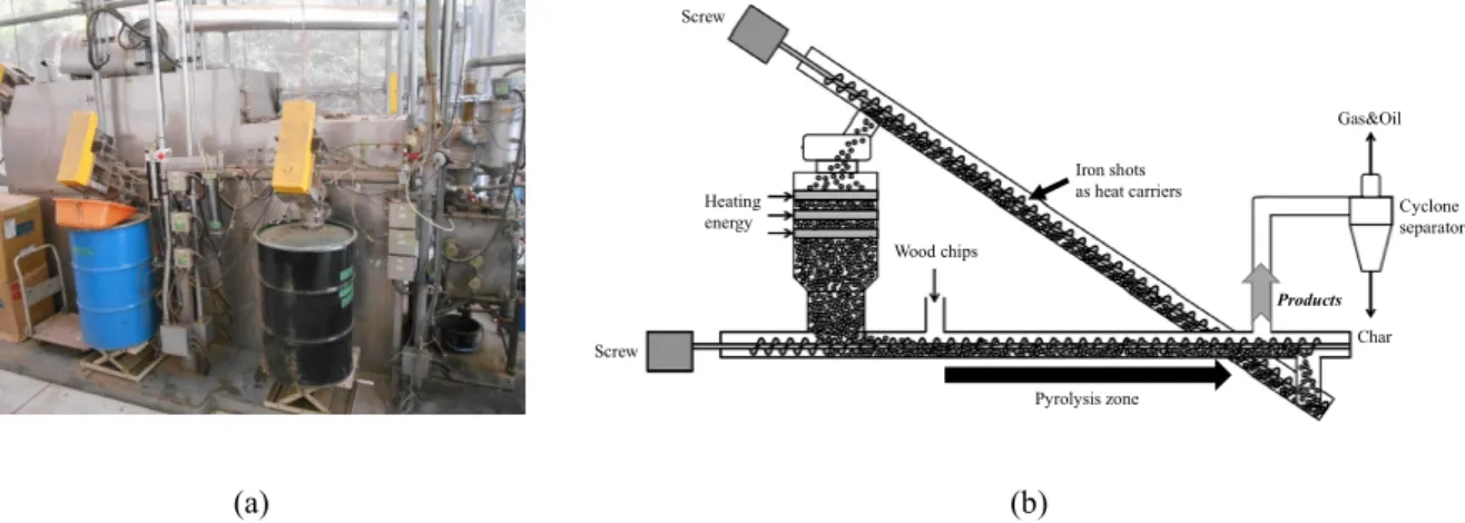
Figures 1 presents an overview of the flow system and development of a fast pyrolysis reactor with Auger-type
modules. Japanese cedar chips without bark parts (Iwaki, Fukushima, Japan) were used as the biomass feedstock after drying (2–3 nm, <10 wt% H2O). The feeding rate was 25 kg/h in the main experimental condition (in some
cases, 40 kg/h was also examined). Iron shots (SB-20; 1.4–1.7 mm) heated at 450–450°C were circulated as heat carriers by the conjugated two screw lines in the reactor system. The horizontal Auger-screw proceeded the pyrolysis reaction, and the sloped Auger-screw carried the Iron shots to the heater head for reheating. The fine char was first collected by a cyclone separator; then pyrolysis oil was condensed at a scrubber system. The off-gas was not trapped at this time. In the initial system condition, pure water was set into the scrubber as a good condensing agent for pyrolysis oil. Figure 2 shows that the water in the scrubber collector was concentrated gradually by producing pyrolysis oil and obtaining a dark color as a function of time during 24 h operation at a 25 kg/h feeding rate. Wood chips Heating energy Screw Screw Pyrolysis zone Char Gas&Oil Iron shots as heat carriers Products Cyclone separator (a) (b)
FIGURE 1. Developed fast pyrolysis reactor with Auger-type modules (a) overview and (b) schismatic flow system.
(a) (b)
FIGURE 2. Time-course of photography of the as-produced pyrolysis oil in the scrubber collector at 25 kg/h feeding rate:
Performance of the developed compact fast pyrolysis reactor was elucidated from pyrolysis oil properties characterized using various analytical techniques [10–12]. Elemental analysis for carbon (c), hydrogen (H), nitrogen (N), and sulfur (S) contents was conducted using an elemental analyzer (Vario EL3; Elementar Analysensysteme GmbH). Sulfanilic acid (Merck Millipore; C: 41.61, H: 4.07, N: 8.09, S: 18.50 wt%) was used as standard for calibrating the TCD detector. The sample oil (ca. 5–10 mg) was packed with a Tin (Sn) circular cylinder tube under O2 flow (99.5%, >100 ml/min), and was introduced into the furnace at 1150°C under O2/He flow, which was
connected directly to a reduction tube at 850°C. The oxygen (O) value was estimated from the differences in C, H, N, and S values.
Water (H2O) contents were measured using Karl Fischer (KF) titration methodology with a volumetric titration
analyzer (MKA-610; Kyoto Electronics Mfg. Co. Ltd.). After the sample oil (ca. 0.05–0.10 g) was dispersed into HYDRANAL-KetoSolver (Fluka Chemika GmbH), it was neutralized using HYDRANAL-Composite 5K (Fluka Chemika GmbH) agent, of which the activity value was calibrated using pure water before analysis. Three indexes of ash, weight density, and pour point values were estimated, respectively, using Japanese Industrial Standard (JIS) methods K 2272, 2269, and 2249.
The higher heating value (HHV) was obtained using a calorimeter (C200; IKA). The sample oil (ca. 0.5 g) was put into a gelatin capsule (18759 J/g) with an appropriate amount of paraffin chips (46619 J/g) as a combustion enhancer. Then it was sealed in the special vessel with O2 pressurized to 30 bar. Ignition was done using electronic
power (100 J) through cotton yarn (50 J/twist). The lower heating value (LHV) was calculated using H2O content
with a water condensation heat value (40.8 kJ/mol).
A gas chromatograph (7890B; Agilent Technologies Inc.) with a time-of-flight mass spectrometer (GC-TOFMS, AccuTOFTM GCx; JEOL) was used to ascertain the mixed components. A DB-1 capillary column (30 m × 0.32 mm
× 0.25 µm; Agilent Technologies Inc.) was used for separation. After the sample of pyrolysis oil (100 mg) was dispersed in methanol (1 mL), 1.00 µL of the mixture was injected with a split ratio = 10.0 using an auto injector (7683B; Agilent Technologies Inc.). The column oven was kept at 50°C for 3 min; then it was heated from 50°C to 320°C with 5°C/min rate. Mass spectrometry presented results in the range of m/z = 35.00–800.00 during a 3.20– 60.00 min GC program, after tuning at around m/z = 264 with perfluorotributylamine (PFTBA; Wako Pure Chemical Inds. Ltd.).
Fourier transform ion cyclotron resonance mass spectrometry (FT-ICRMS) was conducted using a device (SolariX; Bruker Daltonics Inc.) attached with a 9.4 T superconducting magnet. The pyrolysis oil was diluted as 1 µL/mL concentration with ethanol; then it was introduced/ionized using electrospray ionization (ESI) at 4.5 kV (negative-ion mode). Oleic acid (C18H33O2; 281.24860 Da (monoisotopic) was used as an internal standard for m/z
adjustment. A 2 M (megabyte) dataset (3.84 M points) was acquired for m/z = 100–1200. Five scans of FT-ICR datasets were added to enhance the S/N ratio. From the obtained negative-ion FT-ICRMS spectrum, the estimated composition formulas determined by the actual m/z value below ±1.0 ppm error were listed as the expected compounds (CαHβOχNδ) in the sample. The C, O, and C-O contribution diagrams in the as-prepared pyrolysis oil
were described by the count of the expected formula with the target element number: C number (α) and/or O number (χ).
RESULTS AND DISCUSSION
Figures 3 presents the time-course of physical properties of as-produced pyrolysis oil in the scrubber collector
on C and O element contents, water content, and HHV at 25 kg/h feeding rate. The C values gradually increased concomitantly with decreasing O values as a function of time at the beginning of operation for 10 h. Thereafter, these gave approximately constant values of C: 50 wt% and O: 40 wt%. The water contents also gave a similar tendency to afford approx. 15 wt% at 10–24 h operation. The as-produced pyrolysis oil showed higher C content and lower H2O content conditions. Therefore, the HHV also served the same alterations.
Accordingly, it was expected that condensation of pyrolysis oil into the initial condensing agent (water) was progressing linearly as a function of the operation time within 10 h operation at a feeding rate of 25 kg/h; then the static state for pyrolysis oil generation with constant quality was achieved for additional operation time. It is noteworthy that when we increased the feeding rate to 40 kg/h, such condensation was concluded within 5 h as well (data not shown).
100 90 80 70 60 50 40 30 20 10 0 E le m en t co n te n t (w t% ) 25 20 15 10 5 0 Operation time (h) C O 100 80 60 40 20 0 W at er c o n te n t (w t% ) 25 20 15 10 5 0 Operation time (h) 25 20 15 10 5 0 H ig h er h ea ti n g v al u e (M J/ k g ) 25 20 15 10 5 0 Operation time (h) (a) (b) (c)
FIGURE 3. Time-course of the physical properties of as-produced pyrolysis oil in the scrubber collector at a 25 kg/h feeding
rate: (a) C and O element contents, (b) water content, and (c) HHV.
Figure 4(a) shows GC charts obtained from GC-TOFMS analysis. Peak intensities showed a gradual increase
during initial 10 h operation, and would be similar after 10 h. It is noteworthy that no significant differences were found in the peak patterns in GC-charts during 24 h operation.
Methoxy, Hydroxy Aromatics
OH O
Terpene
OH
Furans, Small alkanes
(a) (b)
FIGURE 4. (a) Time-course of GCTOF-MS chart of the as-produced pyrolysis oil in the scrubber collector
and (b) expected structure of major compounds confirmed using MS at a 25 kg/h feeding rate.
Expected structures of major compounds confirmed by MS analysis are shown in Figure 4(b). Furans and their derivatives such as 2-furaldehyde, 2(5H)-furanone, pentanal, and hydroxyacetone were observed at a shorter retention time (<17 min). A variety of methoxy and hydroxyl aromatic compounds often appeared at widely diverse retention times (15–35 min). Polycyclic compounds, especially terpene-like compounds, were detected at longer
retention times (>45 min). In general, the wood composition was regarded as including the following contents: cellulose (50–50%), hemicellulose (20–40%), lignin (18–35%), and others (1–4%) [13]. Therefore, pyrolysis of saccharides would generate such furans and its derivatives, whereas pyrolysis of lignin produced methoxy and hydroxyl aromatic compounds included in pyrolysis oil. An important concern is that terpene-like polycyclic compounds are attributable to fine biochar that is not removed by cyclone systems.
Acetic acid was also included in pyrolysis oil in large quantities as described in our earlier reports [10–12]. However, it was not detected in the GCTOF-MS study because the short retention time (<5 min) was cut off to protect the MS filament.
Table 1 presents details of the physical properties of as-produced pyrolysis oil at 12 h and 24 h operations at a
25 kg/h feeding rate. Physical properties were comparable with the typical properties of wood pyrolysis oil [7] except for ash index which served a little higher value in our module reactor (vide infra). As expected from the discussion presented above, almost all values and properties showed similar trends for these two pyrolysis oils. As-prepared pyrolysis oil possessed a calorimetric value of approx. 20 MJ/kg, which was apparently almost half the value of conventional fuel oils such as gasoline, light diesel oil, and heavy fuel oil (42–45 MJ/kg). Many efforts have been undertaken to overcome the issue of a low HHV value of pyrolysis oil through dehydrogenation of pyrolysis oil to remove oxygen using a metal-supported catalyst under a pressurized hydrogen condition [12, 14–16]. However, including such an upgraded construction would be difficult in our Auger-type module system because of the concerns about hydrogen usage in rural mountain areas.
TABLE 1. Physical properties of as-generated pyrolysis oil condensed in the scrubber collector at a 25 kg/h feeding rate
Index 12 h 24 h C 52.4 wt% 48.6 wt% H 6.9 wt% 6.1 wt% N 0.3 wt% 1.2 wt% S <0.1 wt%[a] 0 wt% O 40.4 wt% 44.1 wt% H2O 15.3 wt% 17.8 wt% Ash 0.364 wt% 0.339 wt% Pour point -10.0°C -10.0°C
Weight density >1.180[a] >1.180[a]
Higher heating value (HHV)
21.0 MJ/kg (5.0 kcal/g)
20.3 MJ/kg (4.8 kcal/g) Lower heating values
(LHV)
19.6 MJ/kg (4.7 kcal/g)
19.0 MJ/kg (4.5 kcal/g)
[a] Limit of detection
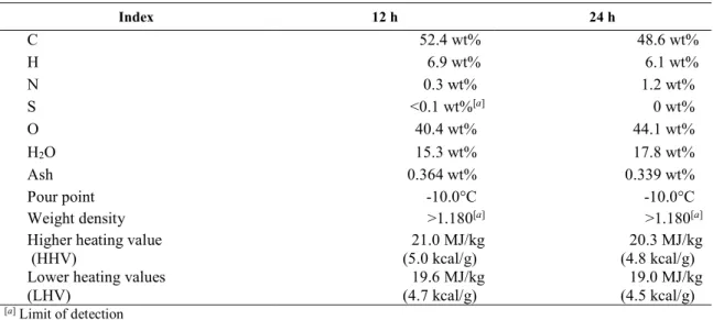
For details of properties of petroleum-based and biomass-based fuels, FTICR-MS analysis has been a versatile discussion tool [10–12, 17–20]. Therefore, we used FT-ICRMS analysis to compare differences between 12 h and 24 h operation pyrolysis oils further. Figure 5 depicts the negative-ion FT-ICRMS broadband spectra of as-prepared pyrolysis oils. Both broadband spectra served a variety of peaks below m/z < 730. According to exact mass estimation analyses, 1836 and 1974 compounds with CαHβOχNδ formula were ascertained, respectively, for 12 h and
24 h. The quantity of each compound could not be ascertained using this analytical technique: discussion of the quantity of each compound was difficult given the intensity of the broad spectrum.
(a) (b)
FIGURE 5. Negative-ion FT-ICRMS broadband spectrum of as-prepared pyrolysis oil obtained at
(a) 12 h and (b) 24 h operation in the range of m/z = 100–1200.
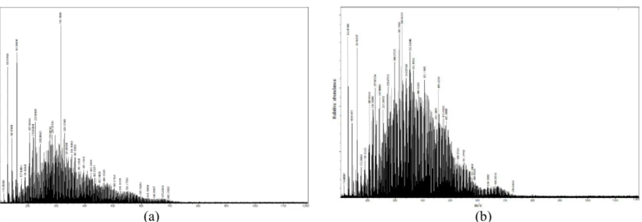
Figures 6 and 7 respectively show the C number (α) or O number (χ) distribution and the C–O number (α-χ)
correlation distributions in pyrolysis oils obtained at 12 h and 24 h operation. These were drawn based on the assigned CαHβOχNδ formulas by FT-ICRMS analysis. Results show that pyrolysis oil was constructed mainly from
5-45 carbons and 2–20 oxygen compounds. A slight difference was found between 12 h and 24 h operation pyrolysis oils determined from the 1D distributions shown in Figure 6. Detailed investigations particularly addressing 2D correlation distributions between C and O shown in Figures 7 revealed only a slight difference especially in higher C and O number correlation areas (C: 30–40 and O: 15–20). The meaning of such a change remains unclear. It is the subject of ongoing work.
6 5 4 3 2 1 0 F re q u en cy ( co u n t% ) 50 40 30 20 10 0
Carbon number in the expected compound (α)
12 h 24 h 10 8 6 4 2 0 F re q u en cy ( co u n t% ) 25 20 15 10 5 0
Oxygen number in the expected compound (χ)
12 h 24 h
(a) (b)
FIGURE 6. Results of FT-ICRMS analysis for (a) carbon number (α) or (b) oxygen number (χ) distribution of
(a) (b)
FIGURE 7. Results of FT-ICRMS analysis for carbon-oxygen (α -χ) number correlation distributions of
(a) 12 h and (b) 24 h operation pyrolysis oils.
The impurities included in the pyrolysis oil are tentatively discussed to provide information about the pyrolysis oil generated by our Auger-type module reactor. Two important expectations were obtained from ash color observation and extraction experiment.
After the ash value test results presented in Table 1, we obtained orange powder as shown in Figure 8(a). In general, non-combustible minerals such as Na2O, K2O, CaO, MgO, SiO2, Al2O3, Fe2O3 (reddish-orange color),
MnO (black color), P2O5, TiO2, SO3, and K2CO3 are anticipated as candidates for biomass-derived ash compounds.
Iron shots were used as heat carriers in our Auger-type module reactor. These would be ground in the reactor eventually by mutual collision. Furthermore, the coarse-grained Fe2O3 (reddish-orange color) would affect the ash
in the pyrolysis oil.
In an additional experiment, to identify the presence of solid impurities in pyrolysis oil, approx. 5 g of pyrolysis oil was “washed” using methanol (40 mL) five times: decantation and centrifugation with MeOH solvent were applied to the pyrolysis oil. After drying the residues under vacuum at room temperature (approx. 25°C), more than 1.19 wt% of black powder was collected (Figure 8(b)). Apparently, some biochar remained in the pyrolysis oil.
(a) (b)
FIGURE 8. Photographs of (a) ash and (b) remaining powder after MeOH decantation in pyrolysis oil generated during 24 h
CONCLUSIONS
The performance of our developed compact fast pyrolysis reactor with Auger-type modules for continuous liquid biofuel production is discussed based on the properties of as-produced pyrolysis oil as a function of the operation time. A 25 kg/h feeding rate of Japanese cedar chips required 10 h at the beginning of operation for condensation processes to afford high-quality pyrolysis oil in our Auger-type module system. This process term can be diminished to <5 h by increasing the feeding rate to 40 kg/h. These observations suggest that improvement of throughput ability is a crucially important factor for future development. After condensation, pyrolysis oil possessing approx. 20 MJ/kg HHV would be generated constantly. These operation performance results were supported by data from GC-TOFMS and FT-ICRMS analyses. Some impurities such as Fe2O3 and fine biochar powder were detected in pyrolysis oil.
However, these were non-toxic and would not inhibit pyrolysis oil combustion.
ACKNOWLEDGMENTS
This research was conducted (in part) as a collaborative work with Toonokousan Co. (Iwaki, Fukushima, Japan) under financial support by National Agriculture and Food Research Organization (NARO), Japan. The authors appreciate Dr. A. Miyazato (Nanocenter, JAIST, Japan) and Dr. S. Hosokai (Advanced Industrial Science and Technology: AIST, Japan), respectively, for their valuable support on FT-ICRMS measurement and technical advice for machine modifications. Measurements of ash, weight density, and pour point values were taken by Yamato Kankyo Co. (Kawakita, Ishikawa, Japan).
REFERENCES
1. Chemicals and Fuels from Bio-Based Building Blocks, edited by F. Cavani, S. Albonetti, F. Basile and A. Gandini (Wiley-VCH, Weinheim, Germany 2016).
2. F. H. Isikgor and C. R. Becer, Polym. Chem. 6, 4497–4559 (2015). 3. X. Cao, S. Sun, and R. Sun, RSC Adv. 7, 48793–48805 (2017).
4. H. Kobayashi and A. Fukuoka, Bull. Chem. Soc. Jpn., in press (DOI: 10.1246/bcsj.20170263). 5. S. Nishimura and K. Ebitani, J. Jpn. Petrol. Inst. 60, 72–84 (2017).
6. S. Nishimura and K. Ebitani, “Catalytic Conversions of Biomass-derived Furaldehydes towards Biofuels,” in Green Chemical Processing and Synthesis, edited by I. Karame and H. Srour (InTechOpen, Rijeka, Croatia, 2017), pp.51–68.
7. D. Mohan, C. U. Pittman, Jr., and P. H. Steele, Energy Fuel 20, 848–889 (2006). 8. A. V. Bridgewater and G. V. C. Peacock, Renew. Sust. Energy Rev. 4, 1–73 (2000).
9. J. N. Brown, “Development of a lab-scale auger reactor for biomass fast pyrolysis and process optimization using response surface methodology,” Master thesis, Iowa State University, 2009.
10. S. Nishimura, A. Miyazato, and K. Ebitani, “Properties of bio-oil generated by pyrolysis of forest cedar residuals with the movable Auger-type reactor” in The Irago Conference 2015, AIP Conf. Proc. 1709, edited by A. Sandhu and H. Okada (American Institute of Physics, Melville, NY, 2016) pp. 020026.
11. S. Nishimura, Enerugii Gakkai Kikanshi /Enermix 96, 474–481 (2017).
12. N. Koike, S. Hosokai, A. Takagaki, S. Nishimura, R. Kikuchi, K. Ebitani, Y. Suzuki, and S. T. Oyama, J. Catal. 333, 115–126 (2016).
13. N. Sun, H. Rodriguez, M. Rahman, and R. D. Rogers, Chem. Commun. 47, 1405–1421 (2011).
14. J. Wildschut, F. H. Mahfud, R. H. Venderbosch, and H. J. Heeres, Ind. Eng. Chem. Res. 48, 10324–13334 (2009).
16. A. N. K. Lup, F. Abnisa, W. M. A. W. Daud, and M. K. Aroua, J. Ind. Eng. Chem. 56, 1–34 (2017).
17. K. Miyabayashi, Y. Naito, M. Yamada, M. Miyake, M. Ushio, J. Fuchigami, R. Kuroda, T. Ida, K. Hayashida and H. Ishihara, Fuel Process. Technol. 89, 397–405 (2008).
18. K. Miyabayashi, Y. Naito and M. Miyake, J. Jpn. Petrol. Inst. 52, 159–171 (2009).
19. Y. Liu, Q. Shi, Y. Zhang, Y. He, K. H. Chung, S. Zhao and C. Xu, Energy Fuel 26, 4532–4539 (2012). 20. I. Leonardis, S. Chiaberge, T. Fiorani, S. Spera, E. Battistel, A. Bosetti, P. Cesti, S. Reale and F. D. Angelis,