Electrochernical Properties of Natural Graphite in the Electrolyte Solutions Containing Propylene ',C, arbonate and
,* *
Nonflammable Q,':rL =' no‑Fluorine Cornpounds fut JJit'hiuin‑Ion Batteries
2010
Takashi Achiha
Aichi Institute of Technology
Contents Chapter 1
Introduction
1‑1 Lithium‑ion secondary battery 1
1‑2 Surface modification of carbon anode materials 2
1‑3 Nonflammable additives and solvents for lithium‑ion secondary battery 5
1‑4 Purpose of the present study 7 1‑5 Scope of the present study , 7
Chapter 2
Electrochemical behavior of natural graphite fluorinated by F2 in propylene carbonate‑containing solvents
2‑3 Results and Discussion 15
Chapter 3
Electrochemical behavior ofnatural graphite fluorinated by CIF3 and NF3 in propylene carbonate‑containing solvents
3‑1 Introduction 3‑2 Experimental
3‑3 Results and Discussion 3‑4 Conclusions
References
35
37
37
50
50
Chapter 4
Electrochemical behavior of plasma‑fluorinated natural graphite in propylene carbonate‑containing solvents
4‑1 Introduction 4‑2 Experimental
4‑3 Results and Discussion 4‑4 Conclusions
References
Chapter 5
Thermal stability and electrochemical properties of nonflammable fluoro‑carbonates for lithium‑ion battery
5‑1 Introduction 5‑2 Experimental
5‑3 Results and Discussion 5‑4 Conclusions
References
Chapter 6
Theunal stability and electrochemical properties of
fluorine‑containing ethers and ester as nonflammable solvents for lithium‑ion batteries
6‑1 Introduction 6‑2 Experimental 6‑3 Results and 6‑4 Conclusions References
Discussion
53 54 55 62 62
65 66 69 88 88
91
92'
94 102 102
Chapter 7
Conclusions
List ofpublications
Acknowledgements
105
1 09
113
Chapter 1
Introductlon
1‑1 Lithium‑ion secondary battery
Since lithium‑ion secondary (rechargeable) battery was put to practical use by Sony Co.
Ltd. in 1 991 its diffasion has been quite rapid. Now it is widely used as electric power sources of many kinds of electric devices [ I J . In the near future, it will become very important electric
power sources for not only mobile devices but also more powerful ones. Lithium‑ion secondary batteries use lithium‑containing transition metal‑oxide cathodes (LiC002, LiCox‑lNix02 etc.), carbon anodes (natural graphite, synthetic graphite etc.), organic solvents and polymer separator. During charging process, Iithium‑ions are inserted into carbon anode to foun lithium intercalated compounds, and return to transition metal‑oxide lattice during discharge process as shown in Fig. I . The electrode reactions during charge‑discharge cycling are as follows.
Charge
Cathode reaction: LiCoO Li CoO + xLi+ + xe (1) 2 (‑‑‑ l‑x 2
DischargeCharge
Anode reaction: 6C + xLi+ + xe (̲̲̲ LixC6 (2)
Discharge
Charge
Cell reaction: 6C + LiC002 Li CoO + LixC6 (3) 1 ‑x 2
Discharge
Power supply or Resistance e Lithium ion
‑ Charge Q)
o <i・・・・ Discharge =;
=; e
o e ・・・・ ' ‑ e
<i・・・・ ‑ O
.*<i・・・・ ‑
"
e e <i・・・・ o e ‑
<i・・・・ ‑
Figure I . Charge‑discharge process oflithium‑ion secondary battery
Metallic lithium anode has a high discharge capacity (3 860 mAhg 1). However, continuous charge‑discharge cycles cause the formation of lithium dendrites on the surface of the lithium anode. These dendrites break through the separator, and directly contact the cathode after many charge‑discharge cycles, which lead to burning or explosion of the battery. In order to prevent direct contact of the lithium anode with the cathode, a graphite intercalation compound of lithium (Li‑GIC) is applied to the anode material. Full intercalation of lithium into highly‑crystalline graphite, such as natural graphite, yields stage I GIC with a composition of LiC6, which corresponds to the theoretical discharge capacity of graphite (372 mAhg 1). The formation of dendrites could be prevented by the use of Li‑GIC. When graphite is used as anode, the electrode potential is low and constant, and irreversible capacity is small.
The open‑circuit voltage of a lithium‑ion secondary battery (3.6‑3.7 V) is several times larger than those for secondary batteries using aqtieous solutions. LiC002 provides constant and high potential of 3.9 V vs. Li/Li+; however, the cost of LiC002 is high, because of the insufficient supply of Co. For this reason, new cathode materials were recently developed, such as LiCox‑1Nix02, LiMh04 etc. Mixtures of natural and synthetic graphites are mainly used as anode materials. Organic solvents incorporate two components. The frrst one is a high‑dielectric solvent, such as ethylene carbonate (EC) or propylene carbonate (PC), which dissolves the inorganic electrolyie (LiPF6, LiCI04 etc.). The second one is a low‑viscosity solvent, such as dimethyl carbonate (DMC), methyl ethyl carbonate (MEC) or diethyl carbonate (DEC). For high‑crystalline graphite such as natural graphite, an EC‑containing solvent should be used to fonn a stable surfaee film, called Solid‑Electrolyie Interphase or Interface (SEI), with the electroehemical decomposition of a small amount of solvent. PC caunot be used for high‑crystalline anodes, because the formation of SEI is slow and the
electrochemical decomposition of solvent continues. However, PC can be used for
low‑crystalline carbons.
1‑2 Surface modificatlon of carbon anode matenals
The crysallinity of carbon materials widely varies. Some low‑crystalline carbons have high discharge capacities, but large irreversible capacities are also observed. Anode should have a small irreversible capacity, that is, high coulombic efficiency (coulombic efficiency = discharge capacity/charge capacity). If anode has a large irreversible capacity, utilization of oxide cathode is largely reduced. For this reason, graphitic materials are mainly used as anode.
Graphite has a constant and low potential, a constant discharge capacity (good cycleability) and small irreversible capacity (high first coulombic efficiency). High‑purity natural graphite and synthetic graphite are usually used anodes. Surface disorder of high‑crystalline graphite is normally lower than that of low‑crystalline carbon. For graphite with low surface disorder, EC‑containing solvent should be used to form SEI with decomposition of a small amount of organic solvent. PC cannot be used for graphite because electrochemical decomposition of PC
continuously occurs. It is very convenient if PC can be used for graphite because PC has a very low melting point of ‑55 oC (melting point of EC: 36 oC), whieh enables the use of lithium‑ion batteries in a wide. The molecular size of PC is larger than that of EC. Therefore, the size of lithium‑ion solvated with PC molecules is larger than that solvated with EC. Since the electrochemical redox reactions take place on the surface of solid electrodes, surface structure, in particular the edge structure of carbonaceous anodes, significantly affects the electrochemical characteristics because lithium‑ions are inserted from edge planes. To improve the electrochemical properties of carbonaceous anodes, some surface‑modification methods have been attempted [1‑5], including surface fluorination [1 , 6‑ 1 4], surface oxidation [15‑22], metal or metal oxide coating L2, 23‑29], carbon coating [30‑42], polymer or silicon coating [43‑5l], composite electrodes [52‑74]. Surface modification gives positive effects to carbonaceous anodes regarding the reversible capacities, first coulombic efficiencies, and cyeleability. Methods of surface modification and their effects are summarized as follows.
1‑2‑1 Surface fluonnation
Surface fluorination using F2 gas, and plasma‑fluorination using CF4 gas, were applied to high‑crystalline natural graphite powder samples with different particle size (average particle size: 7, 25 and 40 um [1, 6‑1l]. Fluorination using F2 is a strong oxidation reaction, and
therefore, surface modification with F2 was performed under mild conditions.
Plasma‑fluorination was performed at 90 oC using CF4 gas. Surface fluorination increased BET surface areas and small mesopores with diameters less than 3 nm. Surface disorder, evaluated by Raman shifts, also increased. First coulombic efficiencies of there natural graphite samples were not change by fluorination in I .O mol/dm3 LiCI04 EC/DEC ( I : I vol.).
Surface fluorination of natural graphite powder samples (average particle size: 5 , I O and 1 5 um) with CIF3 was also preformed under same conditions [12]. Surface fluorination of graphite samples reduced the electrochemical decomposition of PC, increasing their first coulombic efficiencies in the PC‑containing electrolyie. Surface fluorination of graphitized petroleum cokes of open the closed edge surface, highly increasing first coulombic
efficiencies [13, 14].
1‑2‑2 Surface oxidation
It was reported that mild oxidation of graphite increased discharge capacity, however, strong oxidation caused degradation of carbon materials [ 1 5]. Capacity increase due to mild oxidation is similar to the results obtained by surface fluorination. Surface oxidation of mesocarbon microbeads (MCMB) effectively removed the surface skin and significantly improved charge‑discharge behavior [ 1 7]. In liquid‑phase oxidation of natural graphite, ammonium peroxysulfate and nitric acid [18], H202 and Ce (S04)2 [19, 20], nitric acid [2 I],
and ammonium peroxydisulfate [22] were used. Surface oxidation increased reversible capacities and first coulombic efficiencies.
1‑2‑3 Metal or metal oxide coatmg
Coatings of metals, such as Ag, Au, Bi, In, Pb, Pd, Sn, and Zn, improves the anode characteristics of graphite [2, 23‑25]. Among them, Ag, Sn and Zn were the most effective in enhancing high rate characteristics [24]. Copper coating on natural graphite increased its reversible capacity and improved cycling behavior [26]. Aluminum coating on natural graphite, using aluminum triethoxide, reduced transfer resistance [27] . A coating of tin oxide on synthetic graphite gave higher capacity than that of uncoated MCMB [28]. Nano‑Ti02 coated graphite has good cycleability in propylene carbonate‑containing electrolytes [29].
1‑2‑4 Carbon coating
Carbon coating is one of most effective method of surface modification [30‑42]. The main effect of carbon coating is large reduction of irreversible capacity, i.e., an increase in first coulombic efficiency. The main method of carbon coating is chemical vapor deposition (CVD) [3 1 , 34‑42]. Chemical vapor infiltration (CVI) is a special type of CVD, which reduces the irreversible capacity of a low‑crystalline carbon having large capacity [3 8‑42].
Another method is to mix graphite with polyvinyl chloride followed by heat treatment at 500 oC [30], or to disperse graphite in a tetrahydrofuran/acetone solution containing coal tar pitch, and then heat‑treat it at I OOO oC [32, 33].
1‑2‑5 Polymer or silrcon coatmg
Other methods include polymer [43‑50] or Si coating [5 1 J . Mixing poly (3‑n‑hexylthiophen) with graphite not only increased capacity, but also reduced irreversible capacity [43]‑
Coatings of gelation [44, 45, 47], polyaniline [47], cellulose [47], polypyrrole [48] and polyurea [49] on graphite significantly reduced irreversible capacities. The graphite mixed with polyacrylic acid (PAA), polymethacrylic acid (PMA) and polyvinyl alcohol (PVA) improved first coulombic efficiencies in propylene carbonate‑containing electrolyies [50]. Si coating on graphite also increased reversible capacity [5 1 J .
1‑2‑6 Composite electrode
Various composite electrodes were prepared and examined for improving anode
characteristics [52‑74]. A Zr02/graphite composite was effective in suppressing the irreversibility ofnatural graphite [53]. Graphite treated with inorganic salts, such as NaC1 andNa2C03, increased reversible capacity and first coulombic efficiency [54]. The PbO/carbon nanocomposite also increased capacity [55]. Many composites of graphite or carbon with metals, such as Ag [57‑59], Cu [59], Sn [60‑64] and Ni [64‑67], have been examined.
Increases in reversible capacity, decrease in irreversible capacity, and improvements in cycleability were reported. Si is an important element in making composites with graphite or carbon. Different types of Si composite, such as SVcarbon [68, 69], Si/Cu/carbon [70], Si/carbon/polyaniline [7l], Si/carbon/graphite [72, 73] and Si/Ni/graphite [74] were examined as new anode materials. It was reported that these composite electrodes improved cycleability and showed high reversible capacities, between 700 and 800 mAhg 1.
1‑3 Nonfl'anunable additives and solvents for lithiuln‑ion secondary battery
The safety problem is one of the most important issues for the practical use of lithium‑ion batteries. They use flamnrable organic solvents as compared to other secondary batteries that use aqueous electrolyie solutions. Overcharge and over‑discharge of lithium‑ion secondary battery will result in electrolyie decomposition, producing various flammable gaseous species, and increasing the inner pressure and temperature of the battery. Any of these issues will cause the exploding and firing of the battery. To increase the thermal and oxidation stability of lithium‑ion batteries, alternative additives or solvents have been investigated. To improve the therrnal stability of electrolyies, some nonflammable additives and solvents have been examined, including phosphorus compounds [75‑80], phosphates with phenyl groups [8 1 ‑84],
fluorine‑containing phosphorus compounds [85‑89], other compounds [90‑103] and
organo‑fluorine compounds [ I 04‑107]. These compounds improved the thermal stability of lithium‑ion batteries as summarized as follows.1‑3‑1 Phosphorus conrpounds
The trimethyl phosphate (TMP) was investigated in various solvent mixtures. TMP had good oxidation stability and poor reduction stability. P205 rs formed by the oxidation of nonflammable additives and solvehts as soon as the electrolyie is burned. It captures the radicals, H' and HO' in the flame zone, so that the chain reactions for combustion may be weakened or terminated [75]. The reduction decomposition of TMP solvents on natural graphite electrode may be suppressed by mixing EC and PC or EC and DEC cosolvents.
Therefore, TMP was mixed by 20‑30 o/o as one of the components of the solvent mixture.
Electrochemical properties were inferior for high‑crystalline graphite anode, however they can be improved by using amorphous carbon anode or mixing vinyl‑containing additives [80].
Thermal stability of lithium‑ion secondary batteries was improved by using TMP‑containing electrolyies [75‑80].
Phosphates with phenyl groups such as triphenyl phosphate (TPP), tributyl phosphate
(TBP) and cresyl diphenyl phosphate (CDP) were added to electrolyie by 3‑5 wi.o/o as additives [81‑84]. Phosphorus‑based materials promote char formation, Ieading to protective coating of the electrode surface. The surface reaction between the lithiated graphite electrode and electrolyie will be significantly reduced. Therefore, TPP and TBP were added to electrolyie, which reduced the exothermic heat generation between fully charged anode and electrolyie [81‑83]. CDP has a higher boiling point, appropriate viscosity and melting point.
CDP containing electrolyie has shorter self‑extinguishing time, good charge/discharge capacities and cycleability than TMP containing electrolyie [84].
Fluorine‑containing phosphorus compounds: tris‑(2,2,2‑trifluoroethyl) phosphate (TFP), bis‑(2,2,2‑trifluoroethyl) methyl phosphate (BMP) and (2,2,2‑trifluoroethyl) diethyl phosphate (TDP) were mixed with solvents by 20‑40 o/o to investigate thermal stability and electrochemical behavior [85‑89]. It was found that the' electrolyies based on phosphates, with at least two fluorinated alkyls, demonstrate stable cell performance at room temperature, and the presence of these phosphates not only delivers higher cell safety, but also improves the cell capacity retention over a long period of testing. However, the rate capability and low temperature performanee of these nonflammable electrolyies decline with increasing concentration of these phosphates, as a result of higher cell impedance. Nevertheless,
compared with their nonfluorinated counterparts, fluorination introduces higher
flame‑retarding efficiency and lower performance impact. Among three phosphates examined, it was shown that TFP was the best candidate [85‑89].Other phosphorus compounds examined as flame retardant solvents or additives are 4‑isopropyl phenyl diphenyl̲ phosphate (IPPP) [90, 9 1 J , diphenyloctyl phosphate (DPOF) [92, 93], hexamethyl phosphoramide (HMPA) [94], dimethyl methyl phosphonate (DMMP) [95], dimethyl (2‑methoxyethoxy) methyl phosphonate (DMMEMP) [96], tri‑(p‑chloromethyl) phosphate (TCEP) [97], aromatic phosphorus‑containing esters [98] and trimethyl phosphate (TEP) [99]・ It was shown that these phosphorus compounds improved thermal stability of lithium‑ion batteries. In addition, cyclohexyl benzene [97], hexamethoxycyclotriphosphazene [ I OO], Iithium difluoro (oxalato) borate (LiDFOB) [10l] fluorinated phophazenes [ I 02], and
vinyl tris‑(methoxydiethoxy) silane (VTMS) [ I 03] were also studied.
1‑3‑2 Organo fluorme compounds
Several papers were quite recently published for the effect of organo‑fluorine compounds on the electrochemical oxidation stability and charge/discharge behavior [104‑107]. They are new type candidates as nonflammable solvents for lithium‑ion batteries because decrease in HOMO Ievels gives high oxidation stability to fluorine compounds. It was reported in these papers that fluoro‑esters [104], allyl tris‑(2,2,2‑trifluoroethyl) carbonate (ATFEC) [105], 2‑trifluoromethyl‑3‑methoxyperfluoropentane (TMMP) [ I 06], and fluoro‑carbonates [ I 07]
gave the positive effects to oxidation stability of electrolyie solutions and battery
performance.
1‑4 Purpose of the present study
High improvement in the battery performances such as low temperature characteristics, thermal stability and high rate charge/discharge is urgently requested. Because EC‑based solvents should be used for graphite anode, currently used lithium‑ion batteries have difficulty for the use at low temperatures. Since electrode characteristics of carbon materials are governed by crystallinity, surface structure and surface chemical species, surface modification of graphite is one of the good methods to use PC for graphite anode. In the present study, surface fluorination was applied to natural graphite samples. High safety is one of the most important issues for the application of lithium‑ion batteries to hybrid cars and electric vehicles
because lithium‑ion batteries use flammable organic solvents. To avoid firing and/or
explosion of lithium‑ion batteries, nonflammable solvents should be developed.
Organo‑fluorine compounds are new candidates since fluorine substitution of organic compounds reduce HOMO Ievel, i.e. increases oxidation stability. However, fluorine substitution simultaneously decreases LUMO Ievel, which elevates reduction potentials of organic compounds. In the present study, thennal and electrochemical oxidation stability of organo‑fluorine compound‑mixed electrolyie solutions was evaluated, and charge/discharge characteristics of natural graphite were investigated using fluorine compound‑mixed
electrolyie solutions .
1‑5 Scope of the present study
Chapter I describes the principle of lithium‑ion secondary batteries, and summarizes the effects of surface modification and nonflammable solvents on the electrode characteristics of carbonaceous anodes. The purpose ofthe present study and an outline of each chapter are also added.
Chapter 2 presents the results of surface structure changes and charge/discharge behavior of natural graphite fluorinated by F2 in propylene carbonate‑containing solvents
Chapter 3 deals with the surface structure changes and electrochemical behavior of natural graphite of fluorinated by CIF3 and NF3 m propylene carbonate‑containing solvents.
Chapter 4 describes the charge/discharge properties and surface structure of
plasma‑fluorinated natural graphite in propylene carbonate‑containing solvents.
Chapter 5 deals with thermal stability and eleetrochemical properties of nonflammable fluoro‑carbonates for lithium‑ion battery.
Chapter 6 presents the thermal stability and electrochemical behavior of nonflammable fluoro‑ethers and esters for lithium‑ion battery.
Chapter 7 summarizes the results obtained in the present study.
References
[1] T. Nakajima, and H. Groult (eds.), "Fluorinated Materials for Energy Conversion", Elsevier Amsterdam, 2005 .
[2] T. Takamura, Bul. Chem. Soc. Jpn., 75, 3491 (2002).
[3] Y. P. Wu, E. Rahm, and R. Holze, Electrochim. Acta, 47, 3491 (2002).
[4] Y. P. Wu, E. Rahm, and R. Holze, J. Power Sources, 1 14, 228 (2003).
[5] L. J. Ning, Y. P. Wu, S. B. Fang, E. Rahm, and R. Holze, J. Power Sources, 133, 229 (2004).
[6] T. Nakajima, M. Koh, R.N. Singh, and M. Shimada, Electrochim. Acta, 44, 2879
(1999).
[7] V. Gupta, T. Nakajima, Y. Ohzawa, and H. Iwata, J. Fluorine Chem.,1 12, 233 (2001).
[8] T. Nakajima, V. Gupta, Y. Ohzawa, H. Iwata, A. Tressaud, and E. Durand, J. Fluorine Chem.,1 14, 209 (2002).
[9] T. Nakajima, V. Gupta, M. Koh, R. N. Singh A. Tressaud, and E. Durand, J. Power Sources, 104, 108 (2002).
[10] T. Nakajima, V. Gupta, M. Koh, R. N. Singh A. Tressaud, and E. Durand, Mol. Cryst.
Liq. Cryst., 388, [517]/103 (2002).
[ 1 1 J H. Groult, T. Nakajima, L. Perrigaud, Y. Ohzawa, H. Yashiro, S. Komaba, and N.
Kumagai, J. Fluorine Chem.,126, 1 1 1 1 (2006).
[12] K. Matsumoto, J. Li, Y. Ohzawa, T. Nakajima, Z. Mazej, and B. emva, J. Fluorine Chem.,127, 1383 (2006).
[13] K. Naga, T. Nakajima, S. Aimura, Y. Ohzawa, B. emva, Z. Mazej, H. Groult, and A.
Yoshida, J. Power Sources, 167, 192 (2007).
[ 1 4] T. Nakajima, S . Shibata, K. Naga, Y. Ohzawa, A. Tressaud, E. Durand, H. Groult, and F.
Warmont, J. Power Sources, 168, 265 (2007).
[15] E. Peled, C. Menachem, D. Bat‑Tow, A. Melman, and A. Melman, J. Electrochem. Soc., 143, L4 (1996)
J. S. Xue, and J. R. Dahn, J. Electrochem. Soc., 142, 3668 (1995).
[16]
[17]
[18]
[19]
[20]
[2 1 J [2 2 J
[23]
[24]
[2 5 J
M. Hara, A. Satoh, N. tamaki, and T. Ohsaki, Tanso, 165, 261 (1994).
Y. Ein‑Eli, and V. R. Koch, J. Electrochem. Soc., 144, 2968 (1997).
Y. Wu C. Jiang, C. Wan, and E. Tsuchida, J. Mater. Chem., 1 1, 1233 (2002).
Y. P. Wu C. Jiang, C. Wan, and R. Holze, Electrochem. Commum., 4, 483 (2002).
Y. P. Wu C. Jiang, C. Wan, and R. Holze, J. Power Sources, 1 1 1 , 329 (2002).
Y. Wu C. Jiang, C. Wan, and R. Holze, J. Appl. Electrochem., 32, 101 1 (2002).
R. Takagi, T. Okubo, K. Sekine, and T. Takamura, Deniki Kagaku, 65, 333 (1997).
T. Takamura, K. Sumiya, J. Suzuki, C. Yamada, and K. Sekine, J. Power Sources, 8 1/82, 368 (1999).
J. Gao, H. P. Zhang, L. J. Fu, T. Zhang, Y. P. Wu, T. Takamura H, Q. Wu, and R. Holze, Electrochim. Acta, 52, 541 7 (2007).
[26]
[27]
[28]
[29]
[30]
[3 I]
[32]
[3 3 l
[34]
[3 5 J
[36]
[37]
[3 8]
[39]
[4 O J [4 1 J [4 2 J [4 3 l
[44]
[4 5 J
[4 6 J
[47]
[4 8 J
[49]
[50]
Y. Wu, C. Jiang, C. Wan, and E. Tsuchida, Electrochem. Commun., 2, 626 (2000).
S.‑S. Kim, Y. Kadoma, H, Ikuta, Y. Uchimoto, and M. Wakihara, Electrochem.
Solid‑State Lett., 4, AI09 (200 1).
J. K. Lee, D. H. Ryu, J. B. Ju, Y. G. Shul, B. W. Cho, and D. Park, J. Power Sources, 107, 90 (2002).
J. Gao, L. J. Fu, H. P. Zhang, L. C. Yang, and Y. P. Wu, Electrochim. Acta, 53, 2376 (2008).
T. Tsumura, A. Katanosaka, I. Souma, T. Ono, Y. Aihara, J Kuratomi, and M. Inagaki, Solid State lonics, 135, 209 (2000).
H. Wang, and M. Yoshino, J. Power Sources, 93, 123 (2001).
S. Soon, H. Kim, and S. M. Oh, J. Power Sources, 94, 68 (2001).
J.‑H. Lee, H.‑Y Lee, S.‑M. Oh, S.‑J. Lee, K.‑Y. Lee, and S.‑M. Lee, J. Power Sources, 166, 250 (2007).
M. Yoshino, H. Wang, K, Fukuda, Y, Hara, and Y. Adachi, J. Eleetrochem. Soc., 147, 1245 (2000).
H. Wang, M. Yoshida, T. Abe, and Z. Ogumi, J. Electrochem. Soc., 149, A499 (2002).
M. Yoshino, H. Wang, K, Fukuda, T. Ueno, N. Dimov, and Z. Ogumi, J. Electrochem.
Soc., 149, A1598 (2002).
Y.‑S. Han, and J.‑Y. Lee, Electrochim. Acta, 48, 1073 (2003).
Y. Ohzawa, M. Mitani, T. Suzuki, V. Gupta, and T. Nakajima, J. Power Sources, 122, 153 (2003).
Y. Ohzawa, Y. Yamanaka, K. Naga, and T. Nakajima, J. Power Sources, 146, 125 (2005).
Y. Ohzawa, K. Mizuno, and T. Nakajima, Carbon, 46, 562 (2008).
Y. Ohzawa, and T. Nakajima, Carbon, 46, 565 (2008).
Y. Ohzawa, R, Minamikawa, T. Okada, and T. Nakajima, Carbon, 46, 1 628 (2008).
S. Kuwabata, N. Tsumura, S. Goda, C. R. Martin, and H. Yoneyama, J. Electrochem.
Soc., 145, 1415 (1998).
M. Gaberscek, M. Bele, J. Drofenik, R. Dominko, and S. Pejovnik, Electrochem.
Solid‑State Lett., 3, 171 (2000).
J. Drofenik, M. Gaberscek, R. Dominko, M. Bele, and S. Pejovnik, J. Power Sources, 94, 97 (2001).
M. Bele, M. Gaberscek, R. Dominko, J. Drofenik, K, Zupan, P. Koma, K. Kocevar, I.
Musevic, and S. Pejovnik. Carbon, 40, 1 1 17 (2002).
M. Gaberscek, M. Bele, J. Drofenik, R. Dominko, and S. Pejovnik, J. Power Sources, 97/98, 67 (2001).
B. Veeraraghavan, J. Paul, B. Haran, and B. Popov, J. Power Sources, 109, 377 (2002).
Y. F. Zhou, S. Xie, and C. H. Chen, Electrochim. Acta, 50, 4728 (2003).
S. Komaba, T. Ozeki, and K. Okushi, J. Power Sources, 1 89, 197 (2009).
[5 I]
[52]
[53]
[54]
[55]
[56]
[57]
[58]
[59]
[60]
[6 1 J
[62]
[63]
[64]
[6 5 J
[66]
[67]
[68]
[69]
[70]
[7 1 J
[72]
[73]
M. Holzapfel, H. Buqa, F. Krumeich, P. Novak, F. M. Petrat, and C. Veit, Electrochem.
Solid‑State Lett., 8, A5 16 (2005).
I. R. M. Kottegoda, Y. Kadoma, H. Ikuta, Y. Uchimoto, and M. Wakihara, Electrochem.
Solid‑State Lett., 5, A275 (2002).
I. R. M. Kottegoda, Y. Kadoma, H. Ikuta, Y. Uchimoto, and M. Wakihara, J.
Electrochem. Soc., 152, 1595 (2005).
S. Komaba, M. Watanabe, H. Groult, N. Kumagai and K. Okahara, Electrochem.
Solid‑State Lett., 9, A130 (2006).
S . H. Ng, J. Wang, K. Konstantinov, D. Wexler, J. Chen, and H. K. Liu, J. Eleetrochem.
Soc., 153, A787 (2006).
H. Huang, E. M. Kelder, and J. Schoonman, J. Power Sources, 97/98, 1 14 (2001).
K. Nishimura, H. Honbo, S. Takeuchi, T. Horiba, M. Oda, M. Koseki, Y. Muranaka, Y.
Kozono, and H. Miyadera, J. Power Sources, 68, 436 (1997).
Y. P. Wu, C. Jiang, C. Wang, and R. Holze, J. Power Sources, 1 12, 255 (2002).
Y. P. Wu, C. Jiang, C. Wang, and R. Holze, Carbon , 41, 437 (2003).
J. Y. Lee, R. Zhang, and Z. Liu, J. Power Sources, 90, 70 (2000).
Y. S. Jung. K. T. Lee, J. H. Ryu, D. Im, and S. M. Oh. J. Electrochem. Soc. 152, A1452 (2005).
A. Caballero, J. Morales, and L. Sanchez, Electrochem. Solid‑State Lett., 8, A464 (2005).
K. Wang, X. He, J. Ren, C. Jiang, and C. Wan, Electrochem. Solid‑State Lett., 9, A320 (2006).
L.‑Y. Hsiao, T. Fang, and J.‑G. Duh, Electrochem. Solid‑State Lett., 9, A232 (2006).
P. Yu, J. A. Ritter, R. E. White, and B. N. Popov, J. Electrochem. Soc., 147, 1280 (2000).
P. Yu, J. A. Ritter, R. E. White, and B. N. Popov, J. Electrochem. Soc., 147, 2081 (2000).
L. Shi, Q. Wang, H. Li, Z. Wang, X. Huang, and L. Chen, J. Power Sources, 102, 60 (2001).
W.‑R. Liu, J.‑H. Wang, H.‑C. Wu, D.‑T. Shieh, M.‑H. Yang, and N.‑L. Wu, J.
Electrochem. Soc., 152, A1719 (2005).
Z. P. Guo, E. Milin, J. Z. Wang, J. Chen, and H. K. Liu, J. Electrochem. Soc., 1 52, A221 1 (2005).
B.‑C. Kim, H. Uono, T. Satou, T. Fuse, T. Ishihara, M, Ue, and M. Senna, J.
Electrochem. Soc., 152, A523 (2005). . '
Y. Liu, T. Matsurnra, N. Imanishi, A. Hiroya, T. Ichikawa, and Y. Takeda, Electroehem.
Solid‑State Lett., 8, A599 (2005).
X. Yang, Z. Wen, X. Xu, B. Lin, and Z. Lin, J. lectrochem. Soc., 153, A1341 (2006).
H. Uono, B.‑C. Kim, T. Fuse, M. Ue, and J. Yamaki, J. Electrochem. Soc., 153, A1708
[74]
[75]
[76]
[77]
[78]
[79]
[80]
[8 I]
[82]
[83]
[84]
[85]
[86]
[87]
[88]
[89]
[90]
[9 1 J
[92]
[93]
[94]
[95]
[96]
[97]
(2006).
M.‑S. Park, S. Rajendran, Y.‑M. Kang, K.‑S. Han, Y.‑S. Han, and J.‑Y. Lee, J. Power Sources, 158, 650 (2001).
O. P. Korobeinichev, S. B. Ilyin. Chen, V. M. Shvartsberg, and A. A. Chernov, Combust.
Flame 121, 593 (2000).
X. Wang, E. Yasukawa, and S. Kasuya, J. Electrochem. Soc., 148, AI058 (2001).
X. Wang, E. Yasukawa, and S. Kasuya, J. Electrochem. Soc., 148, AI066 (2001).
K. Xu, M. S. Ding, S. Zhang, J. L. Allen, and T. R. Jow, J. Electrochem. Soc., 149, A622 (2002).
X. L. Yao, S. Xie, C. H. Chn, Q. S. Wang, J. H. Sun, Y. L. Li, and S. X. Lu, J. Power Sources, 144, 170 (2005).
X. Wang, C. Yamada, H. Naito, G. Segami, and K. Kibe, J. Electrochem. Soc., 1 53, A135 (2006).
Y. E. Hyung, D. R. Vissers, and K. Anrine, J. Power Sources, 1 19, 383 (2003).
E.‑G. Shim, T.‑H. Nam, J.‑G. Kim, H.‑S. Kim, and S.‑1 Moon, J. Power Sources, 172, 919 (2007).
T.‑H. Nam, E‑G. Shim, J‑G. Kim, H.‑S. Kim, and S.‑1 Moon, J. Electrochem. Soc., 1 54, A957 (2007).
D. Zhou, W. Li, C. Tan, X. Zuo, and Y. Huang, J. Power Sources, 184, 589 (2008).
K. Xu, S. Zhang, J. L. Allen, and T. R. Jow, J. Electrochem. Soc., 149, AI079 (2002).
K. Xu, M. S. Ding, S. Zhang, J. L. Allen, and T. R. Jow, J. Electrochem. Soc., 150, A161 (2003).
K. Xu, S. Zhang, J. L. Allen, and T. R. Jow, J. Electrochem. Soc., .150, A170 (2003).
S. S. Zhang, K. Xu, and T. R. Jow, J. Power Sources, 1 13, 166 (2003).
D. H. Doughty, E. P. Roth, C. C. Crafts, G. Nagasubramanian, G. Henriksen, and K.
Amine, J. Power Sources, 146, 1 16 (2005).
Q. Wang, J. Sun, X. Yao, and C. Chen, Electrochem. Solid‑State Lett., 8, A467 (2005).
Q. Wang, J. Sun, and C. Chen, J. Power Sources, 162, 1363 (2006).
E.‑G. Shim, T.‑H. Nam, J.‑G. Kim, H.‑S. Kim, and S.‑1. Moon, J. Power Sources, 175, 533 (2008).
T.‑H. Nam, E.‑G. Shim, J.‑G. Kim, H.‑S. Kim, and S.‑1. Moon, J. Power Sources, 1 80, 561 (2008).
S. Izquierdo‑Gonzales, W. Li, and B. L. Lucht, J. Power Sources, 135, 291 (2004).
H. F. Xiang, Q. Y. Jin, C. H. Chen, X. W. Ge, S. Guo, and J. H. Sun, J. Power Sources, 174, 335 (2007).
L. Wu, Z. Song, L. Liu, X Guo, L. Kong, H. Zhan, Y. Zhou, and Z. Li, J. Power Sources, 188, 570 (2009).
Y.‑B. He, Q. Liu, Z.‑Y. Tang, Y.‑H. Chen, and Q.‑S. Song, Electrochim. Acta, 52, 3534 (2007).
[98]
[99]
[100]
[10l]
[102]
[103]
[ I 04]
[105]
LI06]
[107]
B. K. Mandal, A. K. Padhi, Z. Shi, S. Chakraborty, and R. Filler, J. Power Sources, 1 61, 1341 (2006).
B. S. Lalia, T. Fujita, N. Yoshimoto, M. Egashira, and M. Morita, J. Power Sources, 1 86, 211 (2009).
C. W. Lee, R. Venkatachalapathy, and J. Prakash, Electrochem. Solid‑State Lett., 3, 63 (2000).
A. Chen, Y. Qin, J. Liu, and K. Amine, Electrochem. Solid‑State Lett., 12, A69 (2009) T. Tsuj ikawa, K. Yabuta, T. Matsushita, T. Matsushima, K. Hayashi, and M. Arakawa, J.
Power Sources, 189, 429 (2009).
H. P. Zhang, Q. Xia, B. Wang, L. C. Yang, Y. P. Wu, D. L. Sun, C. L. Gan, H. J. Luo, A.
W. Bebeda, and T. v. Ree, Electrochem. Commun., 1 1 , 526 (2009).
K. A. Smith, M. C. Smart, G. K. S. Prakash, and B. V.' Ratnakumar, ECS Trans., 1 1 , 9 1 (2008).
S. Chen, Z. Wang, H. Zhao, H. Qiao, H. Luan, and L. Chen., J. Power Sources, 187, 229 (2009).
K. Naoi, E. Iwama, N. Ogihara, Y. Nakamura, H. Segawa, and Y. Ino, J. Electrochem.
Soe., 156, A272 (2009).
T. Achiha, T. Nakaj ima, Y. Ohzawa, M. Koh, A. Yamauchi, M. Kagawa, and H.
Aoyama, J. Electrochem. Soc., 156, A483 (2009).
Chapter 2
Electrochemical fluorinated by F2 in
behavior of natural graphite propylene carbonate‑containing
solvents
2‑1 Introduction
Graphitic materials such as natural and synthetic graphites are mainly used as anodes materials of lithium‑ion batteries because of their low potentials, Iow irreversible capacities (high first coulombic efficiencies), constant reversible capacities and good cycleability. It is known that ethylene carbonate (EC)‑based solvents should be used for graphite anodes for quick formation of surface film (Solid Electrolyie Interface: SEI) with decomposition of a small amount of solvent [1]. Because EC has a high melting point of 36 oC, the use of propylene carbonate (PC) is preferable due to its low melting point, ‑55 oC. Unfortunately PC cannot be used for high‑crystallinity graphite because of continuous decomposition of PC.
However, PC can be used for low‑crystalline carbons with high disorder. This suggests that high‑crystalline graphite is useable in PC‑containing solvents if surface disordering is made by surface modification. Recently some methods of surface modification were applied to improve electrode characteristics of carbonaceous anodes for lithium‑ion batteries [2‑4]. They are carbon coating [5‑16], metal or metal oxide coating [17‑23], surface oxidation [24‑32], surface fluorination [33‑42] and polymer or Si coating [43‑5l]. These methods gave positive effects to reversible capacities, first coulombic efficiencies (irreversible capacities), cycleability and so on. Among them, surface fluorination is an effective method to increase the surface disorder of graphite [33‑42]. Surface fluorination of natural graphite powder samples (average particle sizes: 7, 25 and 40 um; surface areas: 4.8, 3.4 and 2.7 m2/g) by F2 increased R values calculated froyn peak intensity ratios of D‑band to G‑band of Raman shifts, indicating the increase in surface disorder [3 3‑35, 3 7]. Plasma‑fluorination of the same natural
graphite samples with CF4 also increased surface disorder [36]. Simultaneously the fluorination highly increased their surface areas. First coulombic effilciencies of these natural graphite samples were not changed by fluorination in I .O mol/dm3 LiCI04 ‑ ethylene carbonate (EC) / diethyl carbonate (DEC) ( I : I vol.) probably because the large increase in surface areas facilitated the decomposition of EC Ieading to reduction of first coulombic efficiencies [33‑37]. Surface fluorination ofheat‑treated petroleum cokes by F2 destroyed and opened the closed edge planes which were formed during the heat‑treatment at 2300‑2800 oC, increasing surface disorder of petroleum cokes [39‑4 I]. Surface areas of heat‑treated petroleum cokes were nearly the same or only slightly increased after fluorination. These
surface structure changes led to increase in their first coulombic efficiencies in EC‑based solvents [3 9‑4l]. Fluorination of carbon materials with F2 is an electrophilic reaction [52‑54], yielding surface fluorinated layers. Plasma‑fluorination is a radical reaction by chemically active species such as CF3, however, giving surface fluorinated layers because the sample temperature was low (90 oC) [36]. Fluorination reactions of petroleum cokes made by CIF3 and NF3 at 200‑500 oC are radical reactions by chemically active species such as F, Cl, CIF2 and NF2, having surface etching effect [42]. No increase in surface disorder of petroleum cokes was observed after the fluorination. Main effect of surface fluorination by CIF3 and NF3 was increase in first charge capacities of heat‑treated petroleum cokes [42]. However, surface disorder was increased by fluorination with CIF3 when natural graphite samples with high surface areas were used probably because natural graphite has the higher crystallinity than heat‑treated petroleum cokes [3 8]. First coulombic efficiencies of natural graphites with average particle sizes of I O um and 1 5 um increased in I .O mol/dm3 LiCI04 ‑ EC/DEC/PC ( I : I : I vol.) at 1 50 mAlg [3 8]. Importance of high rate characteristics is increasing due to the
application to electric vehicle. Therefore charge/discharge characteristics are often examined at high current densities. From the results hitherto obtained on the surface fluorination of graphitic materials, F2 is a suitable fluorinating agent for increasing the surface disorder of graphite, yielding surface fluorinated layers. In the present study, high crystalline natural graphites were fluorinated by F2 to prepare surface‑disordered graphites which are usable in PC‑based solvents, and charge/discharge behavior of surface‑disordered graphites were examined in PC‑containing solvent. If surface‑modified graphitic materials can be used as anodes in PC‑containing solvents, Iithium‑ion secondary batteries are operated in a wide range of temperatures.
2‑2 Experimental
2‑2‑1 Surface fluorination and characterization of natural graphite sarnples
Starting materials were natural graphite powder samples with average particle sizes of 5
um, 10 um and 15 um (abbreviated to NG5 um, NGIO um and NG15 um; d002 = 0.3355,
0.3354 and 0.3355 nm; purity: >99.95 olo), supplied by SEC Carbon Co., Ltd. Surface fluorination ofnatural graphite sample was performed by F2 (3xl04 Pa) at 200 "C and 300 'C for 2 minutes using a nickel fluorination reactor. Surface fluorinated natural graphite samples were characterized by X‑ray diffractometry (SHIMADZU, XRD‑6100), X‑ray photoelectronspectroscopy (XPS) (SHIMADZU, ESCA 1000 with Mg Ka radiation), IR absorption
spectroscopy (KBr method) (SHIMADZU, FTIR‑8600PC), surface area and meso‑pore size distribution measurements using nitrogen gas (SHIMADZU, Tri Star 3 OOO) and Raman spectroscopy (JASCO, NRS‑1000 with Nd:YV04 Iaser, 532 nm).2‑2‑2Electrochemical measurements for surface‑fluorinated natural graphite samples
Beaker type three electrode‑cell with natural graphite sample as a working electrode and metallic lithium as counter and reference electrodes was used for cyclic voltammetry and galvanostatic charge/discharge experiments. Electrolyie solution was I .O mol/dm3 LiCI04 ‑ EC/DEC/PC (1:1:1 vol.) (Kishida Chemicals, Co. Ltd., H20: 2‑5 ppm). For comparison, electrode behavior of non‑fluorinated graphite samples was ehecked in I .O mol/dm3 LiCI04 ‑ EC/DEC ( I : I vol.). Natural graphite electrode was prepared as follows. Natural graphite sample was dispersed in N‑methyl‑2‑pyrrolidone (NMP) containing 1 2 wi.o/o poly vinylidene fluoride (PVdF) and pasted on copper plate. The electrode was dried at 1 20 'C under vacuum overnight using a rotary pump. After drying, the electrode contained 80 wi.o/o natural graphite sample and 20 wi.o/o PVdF. Potential scan for cyclic voltammetry was made at I .O mV/s (HOKUTO DENKO, HSV‑ I OO). Charge/discharge experiments were performed at current densities of 60 and 1 50 mAlg between O and 3.0 V relative to Li/Li in a glove box filled with
Ar at 25 'C (HOKUTO DENKO, HJIOOI SM8A).
2‑3 Results and Discussion
2‑3‑1 Surface structure change of natural graphite samples by fluorination with F2
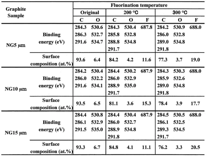
X‑ray diffraction patterns ofnatural graphite samples were almost the same before and after surface fluorination. Diffraction peaks were only slightly broadened. Figures I ‑3 show typical XPS spectra of original and surface‑fluorinated natural graphite samples. Table I summarizes binding energies of C I s, O I s and F I s electrons, and surface composition calculated from peak
areas of XPS spectra. Fls peaks were located at 687.8‑688.0 eV corresponding to C‑F covalent bond. In consistence with F I s spectra, small shifted C I s peaks were observed at 288.8‑289.3 eV. These binding energies of F I s and Cls electrons are slightly smaller than those observed for graphite fluoride, (CF)n (F I s: 689‑690 eV, C I s: 289‑290 eV). This would be due to smaller charging effect of surface‑fluorinated graphite samples with high electric conductivity than that of insulating (CF)n' Surface fluorine concentrations were in the range of 1 1.1‑15.3 at.o/o and 17.7‑20.5 at.o/o for natural graphite samples fluorinated at 200 'C and
3 OO oC, respectively, increase with increasing fluorination temperature. However, there is no large difference in surface fluorine concentrations among three graphite samples. Surface fluorine concentrations were higher than those observed for the same natural graphite samples fluorinated by CIF3 [38]. The difference in the surface fluorine concentrations is ascribed to difference in the reaction mechanisms of F2 and CIF3 with carbon materials. The reaction of F2 with a carbon is an electrophilic reaction, in which F6+ attacks carbon atom with higher electron density (C6 ) and F6 is bonded to another carbon with lower electron density (C6+), mainly giving solid fluorinated layers [52‑54]. Fluorination reaction proceeds with
carbon‑carbon bond breaking and C‑F bond formation. Simultaneously sp2 bond of carbon is changed to sp3 bond. On the other hand, the reaction of CIF3 with a carbon material is a radical reaction with atomic and radical species such as F, C1 and CIF2, in which surface etching of carbon occurs, mainly yielding gaseous fluorocarbons [3 8, 42]. Surface oxygen was reduced by fluorination as given in Table I. Weak O I s peaks were observed in the range of 532.2‑532.9 eV indicating the existence of COH group together with small shoulders at
530.2‑530.9 eV and 534.1‑535.0 eV corresponding to CO group and adsorbed water,
respectively as shown in Figs. 1‑3. Weak Cls peaks showing C‑O bonds were located at 285.8‑286.3 eV for both original and surface‑fluorinated samples (Figs. 1‑3). Very weak shoulders observed at 291.5‑291.8 eV are satellite peaks. The surface oxygen of high purity natural graphite powder ( ; 7 um) was 6 at.o/o when Shimadzu ESCA I OOO spectrometer was used as in the present study [39]・ However, it was I .5‑2.0 at.o/o when Ulvac Phi Model 5500 spectrometer was used [33]・ The difference in the surface oxygen concentrations may be due to the difference in the vacuum levels of the spectrometers. This suggests that the actual concentrations of surface oxygen are lower than those listed in Table I. Figure 4 shows IR absorption spectra of natural graphite samples fluorinated at 300 'C. Broad and weak absorptions are observed at around I 080 cm 1 in all samples. Highly fluorinated graphite(C1.4F‑C2.9F(HF)0.65) showed some strong absorptions between I 080 and 1230 cm 1
corresponding to stretching vibration of covalent C‑F bonds [55]. These absorptions are observed in highly fluorinated graphite in which sp2 and sp3 carbons coexist [55, 56]. Broad absorptions centered at I 080 cm 1 in Fig. 4 seem to consist of several absorptions between 1000 and 1200 cm 1. Another absorption at around 1 554 cm 1 is attributed to vibration of graphene layers (IR active A2* mode) [55].30
20
10
O
CIs 2000C
亀
G99舜娩 岱
Cls 3000C
拶 憂
ヂ ξ
セ
書婁
彦
9
婁
3
ξ 奢 重
働 @㊧轡ゆ 駕
292 288 284 280 292 288 284 280
の畠
而
o
o
一 溜
h
の層 飼㊤層
一
2.O
1.O
0
01s 2000C
9
群も
畜 も駐
も
も 鶏
軸 飾轍
01s 3000C
ゆ
重
φ亀
σ も亀 亀
馬
ら亀 も
蜜
540 536
532,528 540 536 532 528
20
10
O
Fls 2000C
Fls 3000C
696 692 688 684 680 696 692 688 684 Binαing energy/eV
Figure1.XPS spectraofNG5μmand surface−fluo血atedNG5μm.
_一_:NG5μm, 、 :NG5μmfluorinatedat200and3000C.
680
20
10
O
Cls 2000C
騨
藤 戯僻㎎邸轡
擁
奪
暮 亀 箏 彗
る 暑 藝 亀 奪 奪 匙CIs 3000C
饅
暴も
讐 亀 亀
§ § 魯 雪 撃 奪襲 亀
㊧ 蜘鎗鳴ゆ
292
亀
288 284
280 292 ・ 288284 280
の畠
め
9
〇一
h
溜
の層
り㊤自
一
2.O
1.O
O
勤01s 2000C
夕 謹
ξ8
β
9
♂
ξδ
亀 匙
詫01s 3000C
♂ 夢
ξ β
ξ
84
亀
胤も
540 536 532 528 540
536P532 528
10
O
Fls 2000C
Fls 3000C
696 692 688 684 680 696 692 688 684 Bin i皿g e皿ergy/eV
Figure2.】《PS spectra ofNG10μman(1surface−fluo血atedNG10μm.
一一一一:NG10μm, :NG10μmfluorinate(1at200and300。C.
680
20
10
o
Cls
200 *c
c:
e
cs
s
e88 o
Cls
300 "c
p
e e
e
s
e
se e g, 8see
292 288 284 280 292 288 284 280
e, D
v)e 2.0
o
1‑l
¥
>b J' 1 fl c'D l'U
O
Jl
1 O
Ols
200 *c
e
s
e
e se
ee
e
se e
s e
s s s
s
% s
Ols
300 "c
if
e
s
e8
e
a
ge e
e
t
e s s
s
e e es
s ss s
540 536 532 528 540 536 532 528 20
10
o
Fls 200 *c
Fls 300 "c
696 692 688 684 680 696 692 688 684
Binding energy I eV
Figure 3. XPS spectra ofNG15 um and surface‑fluorinated NG15 um.
‑ ‑ ‑ ‑ ‑ : , : NG15 um fluorinated at 200 and 300 'C. NG15 um
680
Table I. Binding energies and surface composition
of original and surface‑fluorinated natural graphite samples, obtained by XPS.
42
40
38
(a)
ee 28 .
O
c'S e
. . .* (,D 26
c I
;
E
24
8
7
(b)
(c)
1600 1200 800
Wave number / cm 1
Figure 4. IR absorption spectra of (a) NG5 um, (b) NGIO um and (c) NG15 um fluorinated at 300 'C.
Surface area and total pore volume of non‑fluorinated sample decreased with increasing particle size as given in Table II. Surface areas and pore volumes were both increased by surface fluorination causing carbon‑carbon bond breaking and fonuation of covalent C‑F bonds. Increase in the surface area and pore volume was the largest in NG5 um among three natural graphite samples, particularly in NG5 um fluorinated at 3 OO oC probably because surface fluorinated layers were thick. However, the increase in the surface areas and pore volumes was small in NGIO um and NG15 um. Increase of surface areas may be correlated with meso‑pore size distributions shown in Fig. 5 , in which meso‑pores with diameters of I .7 and 2.3 nm increased in all surface‑fluorinated samples due to carbon‑carbon bond breaking caused by fluorination. These results are very diffierent from those obtained for the same natural graphite samples fluorinated by CIF3 [3 8]. Surface areas and pore volumes were reduced by the fluorination with CIF3 due to the radical reaction having surface etching effect.
Table II. Surface areas and total meso‑pore volumes of original and surface‑fluorinated natural graphite samples.
12.0
8.0
4.0
6.0
*
'eJD
rb
rb , 4.0
o
e
FI
¥
q,:S e 2.0
‑ >
(L)
e f
4.0
2.0
)
* ,
e e
eee
(a)
S
li ,*
:
!
(b)
I
.
I' *
..
(c)
10
Pore diameter / nm
Figure 5 . Meso‑pore size distribution of original and surface‑fluorinated natural graphite samples.
(a) NG5 um, (b) NGIO um, (c) NG15 um.
original fluorinated at 200 'C
: , """""': , ' ' : fluorinated at 300 'C.
R value calculated from peak intensity ratio of D‑band to G‑band in Raman spectrum expresses the degree of surface disorder of a carbon material. In addition to D‑band, weak D'‑band at 1620 cm 1 is normally observed in Raman spectrum. R values were therefore
calculated after separating D'‑band from G‑band. Figure 6 shows Raman spectra of
non‑fluorinated graphite samples and those fluorinated at 200 oC and 3 OO oC. D‑band intensity was increased by surface fluorination while G‑band intensity was reduced. Intensity of two Raman shifts changed in the similar mauner also in NG5 um and NGIO um. R values increased with increasing fluorination temperature and particle size of graphite, i,e. from NG5 um to NG15 um as given in Table 111. The increase in R values by fluorination using F2 is larger than that obtained for the same natural graphite samples fluorinated by CIF3 [3 8]. This is also attributed to the reaction mechanism of F2 with a carbon. As already discussed, the reaction of F2 with a carbon is an electrophilic reaction, easily forming surface fluorinated layers with C‑F covalent bonds. Carbon‑carbon bond breaking and change of sp2 bond of carbon to the sp3 would have brought about the high surface disordering of natural graphite sam ples.Table 111. R values (=1b/IG) ofRaman spectra
of original and surface‑fluorinated natural graphite samples.
e
, *
o
i.
s
1F2 300 "C F2 200 "C
NG5 unl
G band
‑e e e e , e e , e
D band
‑e e e e e o e e , e , e e e , e e e e , e e , e e e , e
,
F2 300 "C F2 200 "C
NGIO um
e
, e e e
e e e
e e e e e e e e e e e
e e e e e e e e e e e e e e e e , e e , e e e e e e e , e e e
F2 300 "C F2 200 "C
NG15 um
e
e e
e e e
, e e e , , o e o e e
e e e e , e , e e e e e e e e e e e , e e e e e e e e e e e e e
1400 1800
Wave number / cln 1
Figure 6. Raman spectra of original and surface‑fluorinated natural graphite samples.
2‑3‑2 Electrochemical properties of surface‑fluorinated natural graphite samples
Table IV shows first coulombic efficiencies for non‑fluorinated natural graphite samples in 1 .O mol/dm3 LiCI04 ‑ EC/DEC and ‑ EC/DEC/PC solutions. In EC/DEC solution, three
natural graphite samples exhibited higher first coulombic efficiencies than 80 o/o. First coulombic efficiency increased with increasing particle size, i.e. with decreasing surface area, indicating that decomposition ofEC is reduced with decreasing surface area. The result shows that SEI is quickly formed by decomposition of a small amount of EC. On the contrary, first coulombic efficiency decreased with decreasing surface area, i.e. fiom NG5 um to NG15 um in EC/DEC/PC mixture as given in Table IV. It means that decomposition of PC increased with decreasing surface area. The area of edge plane, where desolvation of PC and reduction of PC and Li ion, followed by Li insertion, may mainly occur, decreases with decreasing total surface area, i.e. from NG5 uin to NG 1 5 um. In addition, the ratio of edge plane to total surface area is close to 5 O o/o in case of fine graphite powder such as NG5 um, however, decreasing with increasing particle size, i.e. decreasing total surface area. Since charge/discharge cycling was made at a constant current density (constant current per I g of graphite), actual current density increases with decreasing area of edge plane, that is, from NG5 um to NG15 um. Since SEI formation on high crystalline graphite is more difficult in PC‑based solvent than in EC‑based one, decomposition of PC would be accelerated with decrease in the area of edge plane, that is, with increase in actual current density. Exfoliation of surface region of natural graphite might occur, faeilitating the electrochemical decomposition of PC. In the case of NG5 um, frrst coulombic efficiencies were high in both EC/DEC and EC/DEC/PC solutions (81.4 and 81.8 o/o, respectively as given in Table IV).
NG5 um has the largest surface area, i.e. the largest area of edge plane, among three natural graphite samples. Additionally edge plane has the higher surface disorder than basal plane.
These structural factors may facilitate the smooth formation of SEI on NG5 um even in
EC/DEC/PC.
Table IV. First coulombic efficiencies for non‑fluorinated natural graphite samples in I .O mol/dm3 LiCI04 ‑ EC/DEC and ‑ EC/DEC/PC at 60 nlA/g.
It was found that surface fluorination effectively improved electrode characteristics of
NGIO um and NG15 um with relatively larger particle sizes. Figure 7 shows cyclic
voltammograms obtained for non‑fluorinated graphite samples and those fluorinated at 200 'C and 300 'C. Reduction current at I st cycle indicating the decomposition of PCincreased with increasing particle size as shown in Figs. 7(a), Figs. 8(a) and 8(d). This is consistent with the results given in Table IV. However, reduction peaks at I st cycle for NGIO um and NG15 um, shown in Figs. 8(b) and 8(e), were highly reduced by surface fluorination.
The NGIO um and NG15 um fluorinated at 300 'C showed the similar potential‑current curves to those obtained at 200 "C while NG5 um fluorinated at 3 OO 'C had a large reduction peak at around 0.5 V and another one at around I . 85 V vs. Li/Li indicating the reduction of fluorine atoms bonded to basal plane of graphite [2]. In addition, peak currents of oxidation were also increased by surface fluorination. It means that reversibility of Li intercalation and deintercalation into and from natural graphites was improved by fluorination.
bJD
.¥ b
' uD
IO 1
Sl . I
:5
(,
1000
o
‑1000 1000
c
,6
(a)
i' ' ee ' e
o
‑1500
(b)
ie e ' ee ?e e ,
o 1.0 2.0 Potential / V vs. Li/Li+
3.0 O 1.0
2.0 3.0
Figure 7. Cyclic voltammograms for original and surface‑fluorinated natural graphite samples in I .O mol/dm3 LiCI04 ‑ EC/DEC/PC at I mV/s.
(a) NG5 um, (b) NG5 um fluorinated at 200 'C, (c) NG5 um fluorinated at 300 'C.
1 st cycle 2nd cycle
: , """""': , ' ' : 10th cycle.
1000
o
‑1000 1000
e
e'
,' e'
e ,e ,
e$
(a)
, e
e i'ie ,,,e
ee e ,
e
6 e" e e " 's, , 5 ie e"'e"
e'
? 'e
'OJD
?*
5 O
:
()
o
'i
e
ea(b)
ie 'C e '
(d)
‑1500 1000
ei
cfe
es
(e)
' 'i' e'8e
o
'$
ec
(c)
, ie Pe e e Bse
:
eee
e e
"
e e$
,
(D
:eiei e '
:, e‑1500
o 1.0 2.0
3.0 1.0
OPotential / V vs. Li/Li+
2.0 3.0
Figure 8. Cyclic voltammograms for original and surface‑fluorinated natural graphite samples in I mol/dm3 LiCI04 ‑ EC/DEC/PC at I mV/s.
(a) NGIO um, (b) NGiO um fluorinated at 200 'C, (c) NGIO um fluorinated at 300 "C.
(d) NG15 um, (e) NG15 um fluorinated at 200 'C, (D NG15 um fluorinated at 300 'C.
1 st cycle 2nd cycle