An ammeter that indicates electric current by the movement of a light spot, and voltage by the color
Masahiro Kamata and Chiho Hara
Department of Science Education, Faculty of Education, Tokyo Gakugei University, Nukuikita-machi, Koganei-shi, Tokyo184-8501, Japan
Abstract
A new type of ammeter (PikoPikoII) has been developed which indicates the measured current by the movement of a spot of light and the voltage by the color of the spot. Since this tool can make students feel as if they are observing a visual image of electricity, it is easy to prepare schematic explanations on electric circuits that match the students’ observations using the PikoPikoII. From such a viewpoint we used a restaurant model with a PikoPikoII in a trial lesson for junior high school students, and found that such a combination is very helpful to them in comparison with explanations using ordinary fluid-flow models.
1. Introduction
In Japan, students start to learn about electricity from the 3rd grade in elementary school, and use ammeters in the 4th grade. Although the use of the ammeters is not technically difficult to master for elementary school students, it is difficult for them to obtain the correct concept about electricity this way because ordinary ammeters do not show the physical phenomena that occur in the circuit.
With this in mind, we developed a new type of ammeter (PikoPiko) that indicates electric current by the movement of a spot of light, and we have reported the educational effect of this PikoPiko in our previous papers
1,2).
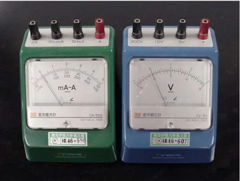
On the other hand, voltage is an important parameter in the study of electricity. Although students learn about voltage in the upper grades (usually in the 8th grade in Japan) it is not easy for them to understand the physical meaning of voltage, and many students confuse it with electric current. This is partly because electricity itself is invisible and students cannot create a clear image of it. In addition, it is partly because the outside appearance of ordinary voltammeters is too similar to the appearance of ammeters as shown in Fig.1. Thus, even if students can carry out experiments as their textbooks indicate, it is difficult for them to draw the correct concept from their own experiments.
With this in mind, we have developed a new ammeter (PikoPikoII) that indicates current by the
movement of a spot of light and shows voltage by the color of the spot. Since the current and the
voltage of electricity in a circuit can be visualized by this, it is quite possible to use the PikoPikoII to build an educational model that has high consistency. This model will be presented later in this paper as well as our trial lessons for practical research of the PikoPikoII.
2. PikoPiko with a new voltammeter function
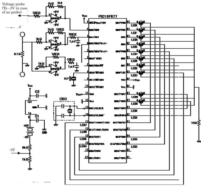
The outside appearance of the PikoPikoII is almost the same as our ordinary PikoPiko as shown in Fig.2 but the hardware in it is completely different. In the case of the PikoPikoII, the moving direction/velocity of the light spot and its color are controlled by a PIC16F877 (Microchip). The block diagram and the circuit diagram of the PikoPikoII are illustrated in Figs.3 and 4, respectively.
The direct current is converted to DC voltage when it flows through a resistor (0.1Ohm) on the left side of the diagram in Fig.3. After this voltage signal is amplified by an operational amplifier (OP07) the signal is input into the PIC16F877 and processed to control the direction/velocity of a light spot on an array of 10 light emitting diodes. As with our previous PikoPiko, the larger the current, the faster the spot moves, and the direction of movement of the spot represents the direction of the current. The PikoPikoII has another probe (voltage probe in Fig.3) to find the ground level of the circuit to be measured. This probe is connected to the negative pole of the battery in the circuit and the voltage between the measuring point and the ground level is measured using the same PIC16F877, which sets the color of the spot as green, yellow or red when the voltage is 0~1, 1~2, or 2~ V, respectively. These colors were determined based on students’ opinions. Since they are accustomed to computer games in which green usually indicates “Energy Full” and red indicates
“Energy Empty”, they seem to take green as something with high potential and red as something with low.
In the early stages of our work, we used a lead wire as the third probe to be connected to the negative pole of the battery. However, when students found three lines coming out of one PikoPiko, many of them seemed puzzled. Thus we used a sheet of stainless steel instead of a lead wire and asked students to make the circuit on that. Since there is a terminal (voltage probe) on the bottom face of the PikoPikoII and another terminal on the battery holders as shown in Fig.5, when students put them on a stainless steel sheet, these two terminals are connected electrically.
The whole appearance of the circuit with PikoPikoIIs built in is presented in Fig.6. Since the velocity of the light spot of each PikoPikoII is the same, students can recognize that the flow (or electric current) in the circuit is constant. On the other hand, when they see the different colors of a light spot on each PikoPikoII, they are expected to recognize some physical difference in electricity (or a voltage).
3. Educational model that has high consistency with PikoPikoII
Although several kinds of educational model are used for the study of electricity, the relation
between the circuit and the model is not so concrete in most cases because electricity itself is invisible. Since we have developed a tool that makes the current and the voltage visible in a pseudo sense, it is possible to develop an educational model as shown in Fig.7 that has high consistency with students’ observations in their experiments. In this model, a human-like character representing the electric charge comes out of the restaurant (battery), makes a light in the working room (mini-lamp), and returns to the restaurant. The character coming out of the working room is exhausted and very hungry. After he eats food in the restaurant he recovers from the fatigue and can go to work again. Thus the electric current was presented as the movement of the characters and the voltage is expressed as their fullness or ability to work. Although the original of this model (the restaurant model) itself is not our own design and similar models are often used in many applications and classes, we have adapted the design so that the character coming out of the restaurant is colored green and the exhausted one is colored red so the color matches the color of the light spot of the PikoPikoII.
One of the biggest merits of this model is the ease of explaining why the brightness of the mini light is the same in both a simple circuit with one battery and in a circuit with two batteries connected in parallel. In both cases, the fullness of the characters coming out of the restaurant is the same because they pass only one restaurant, and therefore the ability to light up is also the same.
In the case of series connection, the character can eat twice in two restaurants, which means his ability to make light is much greater than the former case. (It must also be assumed that the fuller the characters are, the more quickly they can finish their work so that more characters can move in the circuit in unit time. This assumption is necessary to explain the increase of the current according to the increase of the applied voltage. )
4.Conclusion
Practical research was carried out at Setagaya Junior High School attached to Tokyo Gakugei University, with 162 students in the eighth grade (13 or 14 years old), in order to clarify whether our new ammeter PikoPikoII could be accepted by students and how the restaurant model was evaluated by them when it was presented with the PikoPikoII.
As far as the number of pupils who understood the correct concept of electricity is concerned, there is currently little evidence to support the superiority of the PikoPikoII over ordinary teaching methods using the fluid-flow model. However it can be said that students accepted the PikoPiko more positively, and felt that the PikoPikoII and the restaurant model were very helpful for their study. Although the fluid-flow model for electric circuits has been used up until now in schools and is very useful, a restaurant model could be more useful for elementary and/or secondary school students when the PikoPikoII is introduced in their classes because the correlation between students’
observed results and the model is very high.
References
1) Kamata M, Tanaka Y, Ishii K, Horii T and Shinbo I, 1997 Phys. Educ. Japan 45 326–7 2) Kamata M, Shinbo I, Tanaka Y, Ishii K and Horii T, 2001 Physics Education, 36 243-249
Acknowledgement
This work was partly supported by a Grant-in-Aid for Scientific Research(C) 16500541
List of figures.
Fig.1 An ammeter and a voltmeter used in elementary school and junior high school in Japan.
Fig.2 External appearance of our new PikoPikoII
Fig.3 Block diagram of PikoPikoII
Fig.4 Circuit diagram of PikoPikoII
Fig.5 Voltage probes put on the bottom surfaces of PikoPikoII and battery holders.
Fig.6 PikoPikoII connected in the circuit.
Fig.7 The restaurant model and the corresponding circuit with PikoPikoII built in
Fig. 1 An ammeter and a voltmeter used in elementary school and
junior high school in Japan.
Fig.2 External appearance of our new PikoPikoII
Amplifier for
-
direction Amplifier for + directionbuzzer
Minus terminal of the battery
Voltageprobe
Amplifier for voltage measurement
2 color LED
Fig.3 Block diagram of PikoPikoII
Voltage probe (To –3V in case of no probe)
-3V