• 検索結果がありません。

SURVEY ON ENVIRONMENTAL IMPACT OF CARBONATION PROGRESS AND REBAR CORROSION IN ACTUAL CONCRETE STRUCTURE

N/A
N/A
Protected

Academic year: 2021

シェア "SURVEY ON ENVIRONMENTAL IMPACT OF CARBONATION PROGRESS AND REBAR CORROSION IN ACTUAL CONCRETE STRUCTURE"

Copied!
8
0
0

読み込み中.... (全文を見る)

全文

(1)

SURVEY ON ENVIRONMENTAL IMPACT OF CARBONATION PROGRESS AND REBAR CORROSION IN ACTUAL CONCRETE

STRUCTURE

Takeshi IYODA

1

and Satoshi Maehara

2

1

Department of Civil Engineering, Shibaura Institute of Technology, Japan

2

Tokyu Construction Co, L.t.d, Japan

ABSTRACT

The progress of carbonation in reinforced concrete leads to a decrease in durability of concrete structures. Since the cause of carbonation is carbon dioxide in air, carbonation can be proceed anywhere. However, it is said that the progress of carbonation is suppressed in places where spraying water such as rain and high humidity. On the other hand, the presence of water and oxygen are indispensable for corrosion of rebar on concrete structures. As described above, the influence of the environment placed greatly acts in the progress of carbonation and corrosion of reinforcing bars.

It was conceivable for carbonation and corrosion of rebar, depending on supply of water with liquid such as rain and the influence of humidity in the atmosphere. Therefore, this study aimed to organize the influence of the environment based on the survey result of the deterioration due to carbonation in the actual structures for a long period in Japan. As a result, it was possible to evaluate the degree of carbonation progress and reinforcing bar corrosion by the presence or absence of supply of water, including the difference in the type of cement. Therefore, it was found that the influence of cover concrete was greatly for carbonation and corrosion of rebar. When the cover concrete is large, there were cases where cracks of concrete did not occur even if the reinforcing bars had already corroded. On the other hand, when the cover concrete was small, there were cases where the rebar corroded and cracks occurred even without direct water supply in concrete structures.

Keywords: Carbonation, Rebar corrosion, Supplying water, Environment, Actual Concrete structures

1. INTRODUCTION

Reinforced concrete structures are damaged by carbonation, which is one of typical deterioration of

concrete. Alkalinity in concrete is lowered by carbon dioxide in the atmosphere. Therefore, it is

known that rebar corrosion occurs. When the reinforcing bars are corroded, crack will occur on

cover concrete, peeling or spalling concrete due to the volume expansion pressure of the corrosion

products of reinforcing bars. Progress of carbonation is due to carbon dioxide gas penetrating into

the pore structures in concrete. Therefore, it is considered that progression is difficult to proceed in

(2)

a water-containing state in which the inside of the pore is saturated. On the other hand, it is assumed that the supply of oxygen and water is important for reinforcing steel corrosion, and the progress is faster as the water content in the pore structures. In this way, since water involvement conflicts with both carbonation progression and rebar corrosion, its analysis is difficult.

In this study, we surveyed the environmental effects of progress of carbonation and corrosion of reinforcing bars through investigation of actual structures that have been used for a long time.

2. SURVEY RESULTS ON PROGRESS OF NEUTRALIZATION 2.1. Outline of survey for carbonation depth

We classified the cores collected from concrete structures using blast furnace slag cement for various environmental conditions and summarized the influence of differences in water supply and relative humidity on carbonation depth. In addition, accelerated carbonation test was carried out using these cores. From these results, the potential of the concrete used in the structure was evaluated. That is, the carbonation resistance possessed by the concrete taking into consideration the difference between using materials, construction conditions and structural members. Differences in the progress of carbonation in the real environment and the accelerating environment were compared using the carbonation depth.

2.2. Concrete core sample overview

The targeted concrete structure is a stadium for 56 years in service which was constructed with blast furnace slag cement. According to the record at the time, the cement used was ordinarily Portland cement replaced with 50%

by mass of blast furnace slag powder. Table 1 shows the collected cores which classified the environmental conditions differ depending on the sampling location such as outside (without supplied water), outside (with supplied water), high humidity environment. When humidity change was measured every hour under each environmental condition, humidity was constantly around 90% under high humidity environment.

A core of φ 75 mm was sampled from the points as Table 1, in a wet coring method, and 1%

phenolphthalein solution was sprayed on the side surface to the degree of carbonation depth. Based

Element Finishing material

① Liang Yes

② Pillar Yes

③ Pillar Yes

④ Pillar Yes

⑤ Pillar Yes

⑥ Liang Yes

⑦ Liang Yes

⑧ Wall Yes

⑨ Liang Yes

① Wall Mortar

② Pillar Yes

③ Wall Mortar

④ Wall Mortar

⑤ Wall Yes

⑥ Wall Mortar

⑦ Wall Mortar

① Pillar No

② Liang No

③ Wall No

④ Wall No

⑤ Wall Yes

⑥ Wall Mortar

⑦ Wall Mortar

Kind of concrete core

Outside Without water

Outside With water

High humidity

Table1 Concrete core sample

(3)

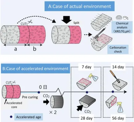
on this result, cutting samples were performed in the un-carbonated part as shown in Fig. 1, and it was divided into a real environment sample and an accelerated environment sample. After splitting cores, the real environment sample was measured, carbonation depth on one side and chemical analysis on the other side. The carbonation depth was determined by measuring the measurement result after 24 hours after 1% phenolphthalein solution was sprayed and the change in the coloration range settled down.

Figure 1: Core sample preparation for test 2.3. Accelerated carbonation test

The test was conducted according to JIS A 1153. Fig. 1 shows the accelerated carbonation test method. The accelerating sample was cut into two parts by a wet method. A pre-curing was allowed to stand at constant environment on temperature as 20 degree Celsius and a humidity as 60% RH.

After completion of the pre-curing, the surface excluding the cut surface was sealed, accelerated carbonation test was carried out with one surface open at 20 degree Celsius and humidity of 60%

RH and carbon dioxide concentration of 5.0%. The carbonation depth was measured at 7, 14, 28 and 56 days after the started accelerated.

2.4. Comparison for carbonation depth on different environmental conditions

The upper part of Fig. 2 shows the measurement results of carbonation depth for each

environmental condition. As environmental conditions, the carbonation depth is larger in outside

without moisture, outside with moisture and high humidity environment. This indicates that the

progress of carbonation is faster as the larger degree of drying. However, there are also places

where there are almost no carbonation progression in outside without water near the dry state, and

(4)

where carbonation progresses fast in a wet state, high humidity environment. These are presumed to have influences other than the environment such as the difference depending on the part even in a place with rain, and the presence or absence of surface coating or finish. Next, the lower part of Fig.

2 shows the accelerated carbonation depth at 56 days. The carbonation depth of many cores was about 20 mm, however cores with early progress of carbonation and slow cores also existed. Thus, also in the potential of concrete itself, there is a difference in the progress of carbonation due to the influence of construction methods and using materials. Since this time using concrete inside the structure, it is considered the influence of cement hydration heat.

Figure 2: Results for carbonation depth in actual and accelerated environment on each cores

Based on these results, it was estimated by the following method in order to estimate the carbonation depth of the real environment considering the potential of concrete. We estimated the carbonation depth of the actual environment for 56 years from the results of the accelerated carbonation depth and the relationship with the carbonation depth in the real environment. The method is as follows. At first, the carbonation coefficient is calculated from the accelerated carbonation depth at 7, 14, 28, and 56 days, on the accelerated carbonation environment, such as concentration of carbon dioxide at 5%. Next, the concentration of carbon dioxide was converted as shown in equation (1), and it was converted to the carbonation rate coefficient in the real environment on carbon dioxide concentration as 0.04%. Finally, the converted carbonation depth in 56 years was obtained.

(1)

Estimated carbonation depth = K

*0.04

√t

(5)

Where, K

*c

: coefficient for concentration of CO

2

is 5%, C: concentration of CO

2

(%) t: age (56years old)

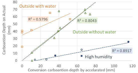
Fig. 3 shows the relationship between the estimated carbonation depth obtained using equation (1) and the carbonation depth of the real environment. The broken line in the graph indicates that the carbonation depth in the real environment is the same as the estimated carbonation depth from accelerated results. In the outside with water and high humidity environment, the easier it is to carbonate in the accelerated environment, the more carbonated it is in the real environment.

Conversely, those which are not easily carbonated as the potential of concrete, the progress of carbonation was slow even in the real environment. However, in the environment on outside with rain, there was no correlation between the real environment and the accelerated environment. This is thought to be the difference for rain, the degree of drying and wetness depending on the climate, the influence of the presence or absence of finish. Focusing at the slope of the lines, there is outside without rain, outside with rain and high humidity environment on the inclination of lines. The outside with rain has the largest slope of line, it is found that it is almost the same as the broken line.

This indicates that the accelerating rate of carbonation in the environment in which the most carbonation tends to progress in the real environment. In a real environment, it can be said that carbonation is suppressed under environmental conditions that water such as rain and high humidity influence. However, there are places where finishing is applied to the data in this research, so further study is required in the future.

Figure 3: Compared with estimated and real carbonation depth

(6)

3. INVESTIGATION RESULTS ON REBAR CORROSION 3.1. Outline of survey

The types of investigated concrete structures are bridges and walls, etc. The survey measurement points were 120 points in total from 18 structures, and about a quarter of them were carried out at the area of peeling and spalling. The construction year was from 1927 to 1989. The investigated structure is located in the general environment in the urban area of Tokyo and in an environmental condition where carbonation is the main factor as a deterioration.

The thickness of cover concrete, carbonation depth and degree of rebar corrosion were obtained by a fog method. In the healthy section without cracks, peeling and spalling etc., the position of the rebar was cleared by a non-destructive test such as the electromagnetic radar method. At the peeling and spalling position, the position of the reinforcing steel bar was specified by visual observation and hammering sound, and the portion where cover concrete remained was selected. At the position, a range of about 100 × 100 mm was fished until the rebar on the cover side was exposed, and the carbonation depth was obtained by measurement of spraying a phenolphthalein solution. The degree of corrosion was evaluated by visual observation of exposed rebar in accordance with the criteria for evaluating the degree of corrosion of reinforcing bars as JIS.

3.2. Results for survey as corrosion rebar

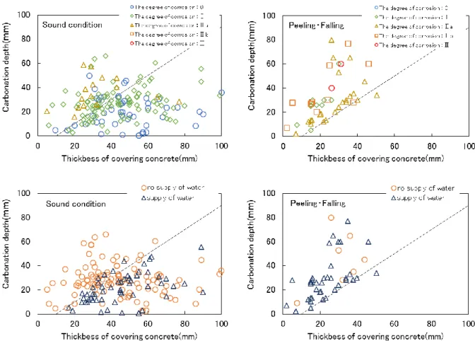
Figure 4 shows the relationship between thickness of cover concrete and carbonation depth. Fig. 4(a) shows the corrosion degree as classified, and (b) shows the influence of the presence or absence of water supply, are divided into the healthy part, the peeling and spalling part. The broken line in the figure shows the remaining 10 mm of carbonation depth, the stationary distribution on the left side of the broken line has the carbonation residue of 10 mm or less, and the rusting shown in the Concrete Standard Specification of the Japan Society of Civil Engineers carbonation beyond the limit is progressing.

According to Fig. 4(a), those with a degree of corrosion of Ⅱa or more of the reinforcing bars occurred where the remaining carbonation depth was approximately 10 mm or less. However, even with corrosion degree IIa, there were also scattered parts that did not lead to peeling and spalling of covering concrete. According to Fig. 4(b), when comparing the influence of water supply or not, there were many places where peeling and spalling did not occur in the case of without water supply. From the above results, it was shown that there was a tendency that peeling and spalling did not occur even if the degree of corrosion of the reinforcing bar was Ⅱa, if there was without water supply.

In the place where there is without water supply, it is understood that even if the carbonation depth

exceeds the remaining carbonation depth 10 mm, the covering concrete does not often peeling and

spalling. In addition, it can be inferred that when the covering concrete is about 40 mm or more,

there are many cases where peeling and spalling does not occur.

(7)

Figure 4: Relationship between thickness of covering concrete and carbonation depth Upper: (a) focusing on the degree of corrosion, lower: (b) focusing on water supply

4. CONCLUSIONS

The results obtained in this research are shown below.

(1) From the actual concrete structure survey using blast furnace cement, it was confirmed that the progress of carbonation is different, depending on the environment, especially water supply.

(2) The carbonation depth at long-term service in an outside without water supply can be estimated from the results obtained in the accelerated carbonation test.

(3) In the corrosion survey due to the carbonation of the actual concrete structure, peeling or spalling of covering concrete occurred in the environment with the supply of water.

(4) When the covering concrete is 40 mm or more, peeling or spalling of the covering concrete due to carbonation is difficult to occur in any environment.

5. ACKNOWLEDGMENTS

This research was carried out as part of Science Research Fund Basic Research (C) 15K 06169

(Research Representative: Takeshi Iyoda). Regarding the survey of concrete structures, we received

(8)

the cooperation of the Architectural Institute of Japan. I would like to thank Ms. Honna who is a graduate my laboratory for works and summary. I will write my gratitude here.

6. REFERENCES

Erika Honna, Takeshi Iyoda (2015): Effect on mechanism of carbonation in different concentration of carbon dioxide and using ground granulated blast-furnace slag, RCCS

Satoshi Maehara, Masanori Ito and Takeshi Iyoda (2016): INFLUENCE OF REBAR CORROSION BY CHLORIDE AND CARBONATION OF MORTAR SURFACE STRAIN, The 7th International Conference of Asian Concrete Federation “SUSTAINABLE CONCRETE FOR NOW AND THE FUTURE”, CD-ROM

T.Iyoda, E.Toyomura, S.Goto and K.Asaga (2014): Study of carbonation mechanism of

blast-furnace slag cement with different carbon dioxide concentrations, pp.1686-1693, IALCCE

Figure 1: Core sample preparation for test  2.3.  Accelerated carbonation test
Figure 2:  Results for carbonation depth in actual and accelerated environment on each  cores
Fig. 3 shows the relationship between the estimated carbonation depth obtained using equation (1)  and the  carbonation  depth of the real environment
Figure 4: Relationship between thickness of covering concrete and carbonation depth  Upper: (a) focusing on the degree of corrosion, lower: (b) focusing on water supply

参照

関連したドキュメント

The Beurling-Bj ¨orck space S w , as defined in 2, consists of C ∞ functions such that the functions and their Fourier transform jointly with all their derivatives decay ultrarapidly

She reviews the status of a number of interrelated problems on diameters of graphs, including: (i) degree/diameter problem, (ii) order/degree problem, (iii) given n, D, D 0 ,

Keywords: continuous time random walk, Brownian motion, collision time, skew Young tableaux, tandem queue.. AMS 2000 Subject Classification: Primary:

Related to this, we examine the modular theory for positive projections from a von Neumann algebra onto a Jordan image of another von Neumann alge- bra, and use such projections

σ(L, O) is a continuous function on the space of compact convex bodies with specified interior point, and it is also invariant under affine transformations.. The set R of regular

Then it follows immediately from a suitable version of “Hensel’s Lemma” [cf., e.g., the argument of [4], Lemma 2.1] that S may be obtained, as the notation suggests, as the m A

Definition An embeddable tiled surface is a tiled surface which is actually achieved as the graph of singular leaves of some embedded orientable surface with closed braid

While conducting an experiment regarding fetal move- ments as a result of Pulsed Wave Doppler (PWD) ultrasound, [8] we encountered the severe artifacts in the acquired image2.