Investigation of Chaos-Generating Circuit Composed of RL Circuits
Yoshinori DOIKE
†Yoko UWATE
†Yoshifumi NISHIO
†and Jingmin XIN
‡(
†Tokushima University) (
‡Xi’an Jiaotong University)
1. Introduction
Recently, chaos phenomena attract many researchers’
attentions. In the field of electrical and electronic engi- neering, various applications using chaos have been pro- posed. To implement these systems, we have to under- stand chaos phenomena in detail. In this study, simple chaotic circuits using two coupled RL circuits are pro- posed. We observe the generation of interesting chaotic phenomenon.
2. Circuit model
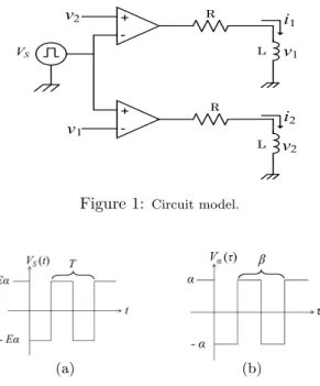
Figure 1 shows the circuit model. In this circuit, two RL circuits are coupled via simple comparators of opera- tional amplifiers. The rectangular voltage wave is inputted to the other input terminals of the comparators and the comparators produce the output voltage ± E which is their power supply voltage according to the input signals. Fig- ure 2(a) shows the rectangular voltage waveform V
S(t).
Eα is the amplitude of the rectangular voltage and T is the period of the waveform. E is the output voltage of the comparators, namely the DC supply voltage of the opera- tional amplifiers.
+ -
- +
R
R L
L
i
1v
2v
1VS
v
1i
2v
2Figure 1:
Circuit model.(a) (b)
Figure 2:
Rectangular voltage waveform.By using the following variables and the parameters, v
n= Ex
n, t = RCτ, T =
RLβ, (n = 1, 2)
the normalized circuit equations are given as follows.
x
1=
(x
10− R
L+ R
R )e
−τ+ R
LR (x
2> V
α)
(x
10+ R
L+ R
R )e
−τ− R
LR (x
2< V
α)
x
2=
(x
20+ R
L+ R
R )e
−τ− R
LR (x
1> V
α)
(x
20− R
L+ R
R )e
−τ+ R
LR (x
1< V
α).
(1)
where V
αcorresponds to V
Sand is shown in Fig. 2(b), x
10, x
20are initial values and R
Lis internal resistance of L.
3. Computer calculated results
Figures 3 and 4 show computer calculated results for V
α= 0.0005, β = 22 R
L= 17 and R = 1000. We observe chaos phenomenon.
Figure 3: Attractor
x1−x2.Figure 4: Waveform.
4. Circuit experimental results
Figures 5 and 6 show circuit experiment results for R
1= 1.003[kΩ], R
2= 1.005[kΩ], R
L1= 14.61[kΩ], R
L2= 14.93[kΩ] and f = 110[kHz], V
S= 6[V ]. We observe chaos phenomenon.
Figure 5: Attractor
v1−v2.Figure 6: Waveform.
5. Conclusions
In this study, we have proposed a simple chaotic oscil- lator including two RL circuits. We have confirmed that the circuit generated chaotic oscillation by both computer calculations and circuit experiments.
14
平成25年度電気関係学会四国支部連合大会 講演論文集 (2013 徳島大学)
2013 SHIKOKU-SECTION JOINT CONVENTION RECORD OF THE INSTITUTES OF ELECTRICAL AND RELATED ENGINEERS (TOKUSHIMA)