A Method for Determining whether a Simulink Model is Ready for
Test Generation
TAKUYA OGATA
†1YUGE LIU
†1KENJI HISAZUMI
†1Abstract: Model-based development (MBD), in which development specifications are written in Simulink, is widely used in the development of embedded control systems. Automatic test generation tools are used to reduce the effort of creating test cases. However, depending on how the model is written, automated generation tools may fail, and it takes time to determine generation failure. In this paper, we propose a method to predict the feasibility of the model test case generation. Specifically, we evaluate the validity of feature generation using the bag of nodes representation of our method and summary statistics of the graphs. The results show that although the AUC of 0.628 is not practically accurate, the initial results using large amounts of data are promising.
Keywords: Simulink, Machine Learning, Graph
1. Introduction
Traditionally, development specifications for embedded control systems have been written in natural language. However, in recent years, model-based development (MBD) [1][2] has become more popular to cope with the expansion of the scale of development, shortening of development time, and improvement of development efficiency. In MBD, development specifications are written in MATLAB/Simulink [3], and there are tools that automatically generate test cases to do this efficiently. The success or failure of test case generation is often not known until the test cases are executed. There are many cases where test case generation succeeds by rewriting the model.
In this paper, we report the results of a study on a method for determining the success or failure of test case generation using a Simulink model for machine learning.
1.1 System Overview
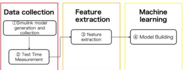
This section proposes a method for determining whether or not to generate tests for Simulink models. The proposed system consists of four parts: a Simulink model collection block, a test case generation time measurement block, a feature extraction block, and a supervised learning block. An overview of the system is shown in Figure 1. In the data collection block, a Simulink model is generated, and data is collected. The test case generation time measurement block applies the Simulink model generated in the data collection block to the test case generation software. It automatically generates test cases and measures the test case generation time. In the feature extraction block, feature extraction is performed from the collected Simulink models. In the supervised learning block, the features extracted in the feature extraction block are used to determine whether the test case generation time has elapsed using supervised learning.
In the following, we describe the feature extraction block in particular.
†1 Kyushu University
Figure 1: Overview of the system
1.2 Feature Extraction
The feature extraction block converts the Simulink model into a directed graph in order to perform feature extraction. This transformation is done by storing internally stored variables into nodes. It then performs the following operations.
1.2.1 Bag of Nodes
Bag of nodes is a method for counting the frequency of nodes and characterizing the number of nodes in a graph; the Simulink model takes some input at the input block, computes it in various arithmetic blocks, and finally performs a control operation with the form of output from the output block. It takes all the shortest paths from input to output and converts the node information of the longest path into frequency information. This is done in order to characterize the most informative path information in the data flow of the control block. First, a list of input blocks (Import block), a list of constant blocks (Constant block), and a list of output blocks (Outport block) are obtained, respectively.
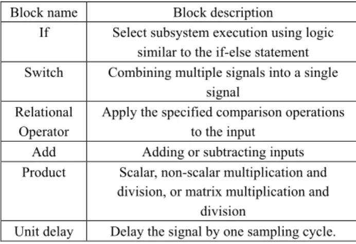
The shortest path to the Outport block of the Simulink model, obtained from these blocks, is obtained. However, the Constant block is converted to “Constant+N” (where N is the 10th order part of Constant’s constant value). The specific blocks shown in Table 1 below are converted to “Specific Block Name + Constant+N” if the input includes a Constant block.
Asia Pacific Conference on Robot IoT System Development and Platform 2020 (APRIS2020)
Table 1. the specific block whose name will be converted
Finally, we characterize the frequency of occurrence of the blocks in the path obtained above as a vector. An overview of the above is shown in Figure 2.
Figure 2: Overview of bag of nodes
1.2.2 Graph statistics
We extract four features (number of edges, number of nodes, the density of the graph, and average cluster coefficient) that can be extracted from a directed graph. We extract the above features in order to include properties such as the complexity of the whole model as features.
Extract features that can be extracted from an effective graph. Add the following four features: the number of nodes in the graph G, n, the number of edges, m, the graph density d, the average cluster coefficient c in the graph G.
2. Evaluation
In this section, we evaluated the proposed method in order to examine its usefulness.
2.1 Evaluation Environment
Table 2 shows the environment in which the test cases were generated. The number of classes used in the evaluation is 54 models that time out and 445 models that can generate test cases without time out. Due to the biased number of test cases, in order to improve the generalization performance, the training split the training data into 10 negative cases and created 10 training models consisting of all negative cases and one segment of positive cases. [4] LightGBM [5] was also used for the training model, and the model was built without adjusting the
hyperparameters.
Table 2. the environment in which the test cases were generated
OS macOS Sierra 10.12.6
Processor 1.3GHz Intel Core i5t
Memory 16GB 1867 MHz LPDDR3
Test case generator
for Simulink models Simulink Design Verifier
2.2 System Evaluation
We compare the discrimination accuracy of the three training models presented in the previous section using the feature extraction method. The results of the evaluation are shown in Table 3. The AUC was 0.628, which is not a high predictive ability result.
Table3: System evaluation results Macro accuracy Macro recall Macro Precision Macro F1-measure Macro AUC 0.802 0.563 0.622 0.570 0. 628
3. Conclusion
In this paper, we proposed a system to determine if the test case generation time for a Simulink model times out or not. To test the usefulness of our system, we conducted an initial evaluation of a randomly generated Simulink model as a case study. The results showed that the model was successfully constructed with an accuracy of 0.628 AUC.
In this study, we focused on data flow in feature extraction, but there are various machine learning methods for current graphs, such as GCN. However, there are various machine learning methods for current graphs, such as GCN, that are expected to be used in future research.
Reference
[1] Akira Ohata, and Kenneth R. Butts, “Improving Model-based Design for Automotive Control Systems Development,” 17th IFAC World Congress, Vol. 41, Issue 2, pp. 1062—1065, 2008.
[2] Mutz, M., Huhn, M., Goltz, U., & Krömke, C. “Model based system development in automotive.” No. 2003-01-1017. SAE Technical Paper, 2003.
[3] The MathWorks Inc.: MATLAB/Simulink, (n.d.). Retrieved October 6, 2020 from http://www.mathworks.com/. [4] Wallace, B. C., Small, K., Brodley, C. E., & Trikalinos, T. A.
"Class imbalance, redux." 2011 IEEE 11th international conference on data mining. IEEE, 2011.
[5] Ke, G., Meng, Q., Finley, T., Wang, T., Chen, W., Ma, W., ... & Liu, T. Y. Lightgbm: A highly efficient gradient boosting decision tree. In Advances in neural information processing systems pp. 3146-3154. 2017.
Block name Block description
If Select subsystem execution using logic similar to the if-else statement Switch Combining multiple signals into a single
signal Relational
Operator
Apply the specified comparison operations to the input
Add Adding or subtracting inputs Product Scalar, non-scalar multiplication and
division, or matrix multiplication and division
Unit delay Delay the signal by one sampling cycle.
Asia Pacific Conference on Robot IoT System Development and Platform 2020 (APRIS2020)