Studies on Separation and Concentration of Metals
Using Forward Osmosis
(正浸透法による金属の分離濃縮に関する研究)
The University of Kitakyushu
Graduate School of Environmental Engineering
Pham Minh Tuan
Preface
This dissertation work was conducted under the supervision of Professor Dr. Kazuharu Yoshizuka and Professor Dr. Syouhei Nishihama at Department of Chemical and Environmental Engineering, the Graduate school of Environmental Systems, The University of Kitakyushu from 2016 to 2021.
The objective is to develop forward osmosis for separation and concentration of metals. The performance of forward osmosis was firstly investigated in order to removing of inorganic trace contaminants such as arsenic and chromium for better understating of separation mechanism. The various operational parameters were also examined to elucidate the concentration behavior of forward osmosis. The author hope that the results obtained in this work give some suggestions for the set-up of membrane technology for removal of heavy metal and concentration of valuable metal on the industrial scale.
Pham Minh Tuan
Department of Chemical Engineering Graduate school of Chemical Engineering The University of Kitakyushu
Contents
Chapter 1 Introduction ... 1
1.1 Background ... 1
1.1.1 Membrane and membrane technology ... 1
1.1.1.1 Microfiltration and ultrafiltration ... 2
1.1.1.2 Nanofiltration and reverse osmosis ... 3
1.1.1.3 Electrodialysis ... 5
1.1.1.4 Forward Osmosis ... 7
1.2.1 Separation and Concentration of Metals by Membrane Separation ... 9
1.2.1.1 General separation of metals by membrane separation ... 9
1.2.1.2 Arsenic and Chromium ... 11
1.2.1.3 Lithium ... 13
1.2 Purpose of this work ... 14
Chapter 2 Removal of Arsenic Using Forward Osmosis and Electrodialysis ... 15
2.1 Removal of Arsenic from Aqueous Solutions by Forward Osmosis ... 15
2.1.1 Introduction ... 15
2.1.2 Experimental ... 15
2.1.2.1 Materials ... 15
2.1.2.2 FO membrane and experimental module of FO ... 15
2.1.2.3 Experimental procedures of FO ... 15
2.1.3 Results and discussion ... 16
2.1.3.1 Effect of As concentration on water flux and As rejection ... 16
2.1.3.2 Effect of the membrane surface orientation on water flux and As rejection ... 19
2.2 Arsenic Removal from Aqueous Solution Using Electrodialysis ... 20
2.2.1 Introduction ... 20
2.2.2 Experimental ... 21
2.2.3 Results and Discussion ... 22
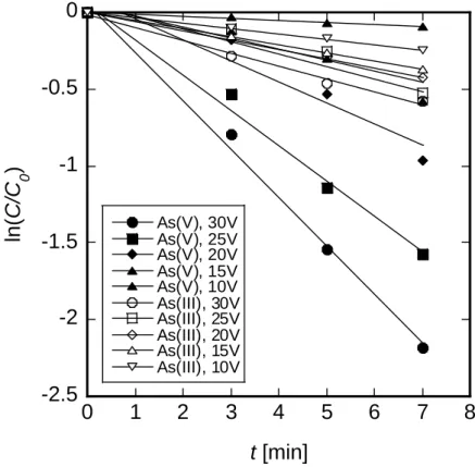
2.2.3.1 Effect of discharged voltage ... 22
2.2.3.2 Effect of pH ... 25
2.2.3.3 Effect of As concentration... 26
2.2.3.3 As removal from geothermal waters by ED process ... 28
2.3 Comparison of Separation Performance of Forward Osmosis and Electrodialysis ... 29
Chapter 3 Removal of Chromium Using Forward Osmosis ... 31
3.1 Introduction ... 31
3.2 Experimental ... 31
3.3 Results and disscussion ... 32
3.3.1 Effect of Cr initial concentration on Cr rejection and water flux ... 32
3.3.2 Effect of draw solution concentration on Cr rejection and water flux ... 33
3.3.3 Effect of pH on Cr rejection and water flux ... 34
3.3.4 Effect of membrane orientation on Cr removal and water flux ... 35
3.4 Conclusion ... 37
Chapter 4 Concentration of Lithium Using Forward Osmosis ... 38
4.1 Introduction ... 38
4.2 Experimental ... 38
4.3 Results and discussion ... 40
4.3.1 Effect of salt concentration in draw solution on water flux and Li rejection ... 40
4.3.2 Effect of pH on water flux and Li rejection ... 43
4.3.3 Effect of Li concentration in feed solution on water flux and Li rejection ... 44
4.3.4 Effect of membrane orientation on water flux and Li rejection ... 45
4.3.5 Concentrating performance of Li from salt lake brine by FO system ... 46
4.4 Conclusion ... 48
Chapter 5 Conclusion ... 50
5.1 Conclusion ... 50
5.2 Suggestion for future work... 51
References ... 52
1
Chapter 1 Introduction
1.1 Background
1.1.1 Membrane and membrane technology
Membrane separation process mainly includes microfiltration (MF), ultrafiltration (UF), nanofiltration (NF), reverse osmosis (RO), ion exchange membrane, electrodialysis, dialysis, gas membrane separation, and liquid membrane. MF, UF, NF, and RO use hydraulic pressure as the driving force, which is caused by a specific pressure difference between both sides of the membrane [1-3]. Apart of the solvent molecules and solutes with the size smaller than the membrane pore can be diffused through the membrane, while the substances larger than the membrane pore size, such as heavy metals, macromolecule compounds of suspended particles are repulsed by the film, thus to achieve the purpose of separation. The pore size of the normal commercial MF membrane ranges from 0.02 to 10 µm and the working pressure is about 0.1 to 1.0 MPa. The pore size range of NF is between RO and UF, about 0.5 to 1.0 nm, the operating pressure is 0.5 to 1.5 MPa. RO is often used to reject the salt in the solution, the pore size is about 0.3 nm, and the operating pressure is 1.0 to 10 MPa [1,2]. Figure 1-1 shows a summary of various membrane procedure applications. The general classification of membrane types in order of decreasing pore size is MF, UF, NF and RO. MF and UF membranes are used as an advanced water treatment process for removing particles including silt and pathogens, while RO and NF are typical process for desalination of saline water [4].
Figure 1-1. The summary of various membrane procedure applications [5].
The general separation mechanism of membrane can be divided into three parts:
Sieving: Molecular sieving is the dominating transport mechanism, when the pore size is comparable to the molecular dimensions. The smaller molecules will permeate, and lager ones will
2
be retained. The dimensions of a molecule are usually described sieving, this is not satisfactory way of stating the molecular size. A shape factor should also be included [1,3].
Charge effect: Due to the special feature of the membrane surface (mostly having fixed negative surface charge), the capacity of separation is influenced by the charge on the surface of the pore (Donnan exclusion phenomena). The charge of the membrane is significant to membrane performance because charge effects the electrostatic repulsion between the ions or charged molecules and the membrane surface [1,3].
Convection-Diffusion mechanism: Selective adsorption/diffusion is mainly utilized for the separation of dense membrane. When fluid flows through the pore as a consequence of either a mechanical or electro- or osmotic pressure gradient, the solute is transported into the pore by both diffusion and convection. The result of these phenomenon is a gradual mixing of material such that the distribution of molecules is uniform. Since the molecules are still in motion and an equilibrium has been established the end result of molecular diffusion is call a dynamic equilibrium [1,3].
Membrane processes are increasingly used for removal of bacteria, microorganisms, particulates, and natural organic material, which can impart color, tastes, and odors to water and react with disinfectants to form disinfection by-products. As advancement are made in membrane production and module design, capital an operating cost continue the decline. The membrane processes discussed here are microfiltration (MF), ultrafiltration (UF), nanofiltration (NF), and reverse osmosis (RO).
1.1.1.1 Microfiltration and ultrafiltration
Microfiltration
Microfiltration refers to filtration processes that use porous membranes to separate suspended particles with diameters between 0.1 and 10 µm, a molecular weight cut-off (MWCO) of greater than 1,000,000 daltons and a relatively low feed water operating pressure of approximately 100 to 400 kPa (15 to 60 psi) [2].
Materials removed by MF include sand [6], silt [1,2], clays [1,2], Giardia lamblia [7], Cryptosporidium cysts [7,8], algae [9], and some bacterial species [10]. MF is not an absolute barrier to viruses. However, when used in combination with disinfection, MF appears to control these microorganisms in water. In its normal operation, MF removes little or no organic matter. However, then pre-treatment is applied increased removal of organic material can occur. MF can be used as a pre-treatment to RO or NF to reduce fouling potential. Both RO and NF have been traditionally employed to desalt or remove hardness from groundwater.
Ultrafiltration
Ultrafiltration uses a fine porous membrane to separate water and microsolutes from macromolecules and colloids. The average pore diameter of the membrane is in the 10–1000 Å range, an MWCO of approximately 10,000 to 100,000 Daltons and an operating pressure of approximately 200 to 700 kPa (30 to 100 psi) [2,3]. The membranes discriminate between dissolved macromolecules of different sizes and are usually characterized by their molecular weight cut-off, a loosely defined term generally taken to mean the molecular weight of the globular protein molecule that is 90 % rejected by the membrane. Ultrafiltration and microfiltration are related processes—the distinction between the two lies in the pore size of the membrane. Microfiltration membranes have larger pores and are used to separate particles in the 0.1–10 µm range, whereas ultrafiltration is generally considered to be limited to membranes with pore diameters from 10 to 1000 Å.
3
UF will remove all microbiological species which can be removed by MF (partial removal of bacterial), as well as some viruses (but not an absolute barrier to viruses) and humic materials. Disinfection can provide a second barrier to contamination and is therefore recommended. The primary advantages of low pressure UF membrane processes which are compared with convection clarification and disinfection processes are:
▪ No need for chemicals (coagulants, flocculants, disinfectants, pH adjustment) ▪ Size-exclusion filtration as opposed to media depth filtration
▪ Constant quality of the treated water in terms of particle and microbial removal ▪ Processes and plant compactness
▪ Simple automation
However, fouling can cause difficulties in membrane technology for water treatment.
1.1.1.2 Nanofiltration and reverse osmosis
Nanofiltration
Nanofiltration membranes have a nominal pore size of approximately 0.001 μm and an MWCO of 1,000 to 100,000 Daltons. Pushing water through these smaller membrane pores required a higher operation pressure than either MF or UF. Operating pressures are usually near 600 kPa (90 psi) and can be as high as 1000 kPa (150 psi). These systems can remove virtually all cysts, bacteria, viruses and humic materials [11]. They provide excellent protection from DBP formation if disinfectant residual is added after the membrane filtration step.
Because NF membranes also remove alkalinity, the product water can be corrosive, and measures, such as blending raw water and product water or adding alkalinity, may be needed to reduce corrosivity. NF also removes hardness from water, which accounts for NF membranes sometimes being called softening membranes. Hard water treated by NF will need pre-treatment to avoid precipitation of hardness ions on the membrane. However, more energy is required for NF than MF or UF.
Reverse Osmosis
Reverse osmosis is a process for desalting water using membranes that are permeable to water but essentially impermeable to salt. Pressurized water containing dissolved salts contacts the feed side of the membrane; water depleted of salt is withdrawn as a low-pressure permeate. Reverse osmosis can effectively remove nearly all inorganic contaminants from water. RO can also effectively remove radium, natural organic substances, pesticides, cysts, bacteria and viruses. RO is particularly effective when used in series with multiple units. Disinfection is also recommended to ensure the safety of water.
Some of the advantages of RO are:
▪ Removes nearly all contaminant ions and most dissolved non-ions,
▪ Relatively insensitive to flow and total dissolved solid (TDS level and suitable for small systems with a high degree of seasonal fluctuation in water demand)
▪ RO operates immediately, without any minimum break in period ▪ Low effluent concentration possible
4
▪ Operational simplicity and automation allow for less operator attention and make RO suitable for small system applications
Some limitations of RO are: ▪ High capital and operating costs
▪ Managing the wastewater (brine solution) is a potential problem ▪ High level of pretreatment is required in some cases
▪ Membranes are prone to fouling
▪ Produces the most wastewater at between 25-50 percent of the feed
Table 1-1 summaries the operational characteristics of the various membrane procedures. The operating pressure for each membrane application is generally based on the pore size of the membranes; typically low pressure range of for MF and UF and higher pressure required for NF and RO. MF separates fine particles which usually involves retaining cells and cell debris while proteins and smaller macromolecules to pass through them. For smaller compounds such as protein and macromolecules, UF membrane with pore size range 1 – 100 nm suited well [12]. In addition to the separation of downstream products of biotechnology industry, UF membrane have also been used to concentrate whey proteins during the production of dairy products [13]. Meanwhile, NF and RO membrane are responsible in separating and recovering much smaller compounds such as solvent, salt, microorganism and dissolved organic compounds due to its smaller membrane pore size. NF and RO separation are based on solution diffusion and charge effects due to the presence of ionisable group on the surface of the membrane [14], thus the properties of these membrane could be exploited either through membrane modification and/or by selecting the best membrane material in order to enhance selective separation of the multivalent ionic species in the feed solution.
Table 1-1. Summary of operating characteristic and the primary mechanism of membrane processes Type Molecular weight cut-off Pressure (bar) Pore size (nm) MTC for water (permeability) Separation Mechanism Application RO 100-300 5-120 0.5 0.05-1.5 L/hm2bar Solution-diffusion
Ultrapure water, Small ions, Micropollutant NF 500-1000 3-20 0.5-2 1.5-30 Solution-diffusion Charge Softening, Small organics, Precursors
UF 5000-10000 0.1-5 2-100 10-1000 Sieving Bacteria, Virus,
Macromolecules
MF 10000 0.1-2
100-10000 1000 Sieving
Turbidity, Protozoa, Bacteria
5
1.1.1.3 Electrodialysis
Electrodialysis is a membrane process driven by a difference in electrical potential over a membrane stack, in which charged compounds are removed from a feed solution. It is a process with a relatively long history, with several papers published in the 1950s on applications, such as the demineralization of sugar solutions [15], desalination [16], and protein separation [17], which are still among applications of interest more than half a century later. What is remarkable is that although the direction has not substantially changed, the interest in electrodialysis has boomed during the past decade [18].
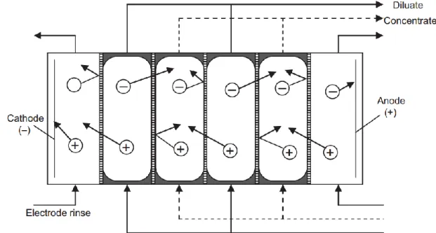
Two kinds of membranes are used in electrodialysis: anion exchange and cation exchange. These two membrane types are alternated in a membrane stack so that a repeating unit is obtained consisting of a compartment with an anion exchange membrane on the left side and a cation exchange membrane on the right, followed by another compartment with an anion exchange membrane on the right side and a cation exchange membrane on the left. Over this membrane stack, a difference in electrical potential is applied using electrodes at both ends of the stack. The feed solution is pumped through the stack. Cations migrate in the direction of the negatively charged cathode and are allowed to migrate through the first cation exchange membrane. The next membrane is an anion exchange membrane, so that the cation cannot migrate further. Anions migrate in the direction of the positively charged anode and can migrate through the first anion exchange membrane. The next membrane is a cation exchange membrane, so that the anion cannot migrate further [18]. The membranes are in principle not permeable for water, although osmosis and electro-osmosis are known to occur in an electrodialysis stack, the ion migration in a salt solution through the membrane stack is shown in Figure 1-2.
Figure 1-2: Ion migration in a salt solution through the membrane stack
In this way, positive as well as negative ions are removed from the feed solution, whereas the neighboring compartments are concentrated. The flow through the feed compartments is usually denoted as the dilute stream; the flow with increasing concentration is denoted as the concentrate stream. The combination of a series of cells (consisting of an anion exchange and a cation exchange membrane, and a dilute compartment and a concentrate compartment) is necessary to decrease the
6
time needed to purify a given stream (in a batch configuration with recycling) or decrease the size of the membranes in the system (in a flow-through system).
Because of the flow of ions through the stack, the electrical current is transferred. The extent to which the electrical current is effectively used for migration of ions that should be removed determines the efficiency of electrodialysis. Apart from the dilute and concentrate flow, an electrode rinse solution is generally applied. The electrodes are positioned in separate compartments to protect the electrode material. At the cathode, hydrogen gas and hydroxyl ions may be formed owing to the dissociation of water (after application of a voltage). The hydroxyl ions may possibly damage the electrode when the electrode material is not carefully selected. An acid is usually added to the rinse liquid of the cathode to prevent damage.
At the anode, the electrode material is at risk because of the formation of metal oxides at the electrode surface (corrosion), which can then dissolve in an acid environment. Possible materials with sufficient resistance are graphite, stainless steel, nickel alloys, or a platinum coating. Reactions with a metal, M, are:
M + xOH- M(OH)
x + xe- (1)
2M + 2xOH- M
2Ox + xH2O + 2xe- (2)
Because of the consumption of OH, hydrogen ions are left, which make the solution more acidic. This dissolves metal ions as:
MOH)x + xH + Mx+ + xOH
-(3)
M2Ox + xH+ 2Mx+ + xH2O (4)
H2, Cl2, and O2 may be formed as a result of oxidation reactions at the anode. These cause
negative effects. Therefore, it is important to make sure that negative ions (such as Cl-) do not have
access to the electrode compartments. For the cathode, this is not problematic because it repels anions, but the anode needs sufficient protection. This can be achieved by using two cation exchange membranes. The electrode rinse solution usually contains SO42-, which would not cause problems at
the anode. Membranes are often exposed to aggressive compounds. Furthermore, because of the electrical resistance, the temperature may increase. Many feed flows (e.g., surface water) contain suspended solids. These may damage the membrane as the result of friction and scouring. The chemical, thermal, and mechanical resistance of the membranes is therefore an important parameter to consider.
The main advantages of ED are, no osmotic pressure, higher quality product, environmentally friendly, no additional chemicals and ion exchange membranes have long useful life. But ED has various limitations. A major disadvantage of ED system is membrane fouling because it reduces the limiting current, reduces the flux, increases the membrane resistance, decreases the ions migration yield and lead to serious polarization problems. Fouling increases with decreasing flow velocity, with increasing current density and colloid concentration [18].
ED has been successfully performed over the last decade mainly in the production of potable water from brackish or seawater, production of pure or ultrapure water, demineralization and deacidification in food or pharmaceutical processing, purification of radioactive wastewater in nuclear power plants, and recovery of water and valuable metals from industrial effluents [19]. The dominant application of electrodialysis is still in desalination. This is a well-established application
7
that can be readily applied. Emerging applications are therefore in the use of electrodialysis for alternative feed waters, ion fractionation, and the use of bipolar membranes in a wide range of production or conversion processes. A typical example of alternative feed water is concentrated brine from an reverse osmosis (RO) plant, in which electrodialysis is used as a technology to prevent damage to marine ecosystems [20]. Fractionation using electrodialysis has main applications for amino acids. Amino acids can be transported selectively across a double membrane system composed of a cation exchange and an anion exchange membrane via pH adjustment of the source phase solution [21]. However, selective removal of other ions is also interesting. One example is the use of monovalent permselective membranes for selective removal of arsenic and monovalent ions from brackish water RO concentrate [22]. In general, transport of monovalent and divalent ions is different because of steric effects and different charge interactions; for example, a removal rate of more than 70% for monovalent ions might correspond to a removal rate below 50% for divalent ions [23]. This can be exploited and optimized for, e.g., the removal of nutrients from wastewater. Electrodialysis with bipolar membranes may be coupled with diffusion dialysis for two-step recovery, with electrodialysis as the second step to recover the remaining concentrations of acid [24]. More applications include the production of morpholine [25]; the separation of lithium and cobalt in view of the recycling of waste lithium ion batteries, in a similar approach as described above for nickel and cobalt [26]. Moreover, there are also more applications in removal processes such as removal of chromium from electroplating wastewater or uranium separation from wastewater [19,27].
1.1.1.4 Forward Osmosis
Forward osmosis (FO) is an emerging membrane technology that utilizes an osmotic pressure difference to drive the water transport through a semi-permeable membrane from the lower osmotic pressure side (referred to as feed solution) to the higher osmotic pressure side (referred to as draw solution) [28]. When a semipermeable membrane separates the solution and a pure solvent, the solution tends to become more diluted by absorbing the solvent through the membrane. If hydraulic pressure is applied on the solution to stop the movement of pure solvent across the membrane and to maintain a condition of equilibrium (no flow of solvent), this equivalent pressure has been termed as osmotic pressure [29]. Osmotic pressure is a colligative property and therefore refers to its chemical potential of the solvent in the solution, or alternatively it includes vapor pressure lowering, boiling point elevation, freezing point depression and osmotic pressure [30].Osmosis therefore describes the natural diffusion of water through a semipermeable membrane from a solution containing a lower salt concentration to a solution containing a higher salt concentration [28]. The osmotic pressure (π) of an ideal dilute solution is given by van’t Hoff’s [31] equation shown below:
π = nMRT (5)
Where n stands for the van’t Hoff factor (refers to the number of individual particles of compounds dissolved in the solution, for example n = 2 for NaCl, n = 1 for glucose); M is the molar concentration (molarity) of the solution; R is the gas constant (R = 0.0821 L·atm·mol-1·K-1); and T is
the absolute temperature (in K) of the solution.
The FO process is in fact an engineered osmotic process in which an artificially high concentrated solution, termed a draw solution (DS), is used on one side of the semi-permeable membrane and the water to be treated is on the other side of the same membrane. Although FO is based on the principle of osmosis, the term ‘forward osmosis’ (FO) has been probably coined to distinguish it from RO, which is the term that has been used for the membrane desalination process for many decades. The semi-permeable membrane, usually made from polymeric materials, acts as a barrier that allows small molecules such as water to pass through while blocking larger molecules such as salts, sugars, starches, proteins, viruses, bacteria, and parasites [32]. Both RO and FO
8
processes use a semi-permeable membrane to separate water from dissolved solutes effectively, although their driving forces are different. The main difference between the two processes is that the driving force in the RO process is created by hydraulic pressure, while the driving force in the FO process is created by the concentration or osmotic difference.
One of the two major challenges of this millennium will no doubt be energy and water, and the need for these two resources is increasing every year to support the rapid population growth and the growing economy as discussed earlier. As the demand for water increases, the issue of water scarcity will continue to grow unless new sources of water are available. Under such circumstances, desalination is expected to play a major role in helping to create new sources of water using the saline water source, which is abundant on the earth. Of the several new potential desalination processes identified, FO has been identified as one of promising emerging technologies for desalination and water reuse applications [33,34]. The FO process operates without the use of any hydraulic energy, and hence, this is one of the main drivers of the FO technology. As the FO process operates at low hydraulic pressure, the cost of the pumps and other membrane accessories would be much lower and ultimately lower capital cost than the RO process. The other perceived advantage of the FO process has been the low fouling issues associated with it. It has been observed through several studies that, fouling issues and challenges are less problematic than the RO process because fouling in the FO process is generally physically reversible thereby avoiding the need for expensive chemical cleaning [35,36].
Despite the inherent advantages and broad application prospects, large-scale commercialization of the FO process has not been adequately possible due to some obstacles such as regeneration and separation of draw solutes, concentration polarization (CP) on the feed side, reverse solute diffusion (RSD), and membrane fouling. Osmosis pressure, which is provided by DS, is the driving force for mass transport. The type and concentration of DS are important factors affecting the performance of FO process [32]. Besides, to separate the draw solutes, energy-intensive methods—such as NF, RO, and membrane distillation (MD) - are often integrated with FO. The investment and energy consumption of the integrated system has become a new problem. Furthermore, CP and RSD are two significant factors impeding FO performance [28]. The water permeation of the membranes will be adversely affected due to the reduced osmotic pressure gradient across the active layer resulting from an increase osmotic pressure on the membrane active layer surface. Also due to the concentration gradient, reverse diffusion of draw solute to the FS seems to be unavoidable. The RSD can not only reduce the concentration gradient and water flux but also increase CP and membrane fouling. Additionally, to reduce membrane fouling, researchers have made a lot of efforts in terms of membrane materials, membrane structures, and process combinations [28].
FO has been studied for a range of applications. Commercial applications, though still limited, are emerging in the water purification field (e.g., extraction bags) and in the pharmaceutical industry (e.g., osmotic pumps). The following section summarizes past and present applications of FO in wastewater treatment and water purification, seawater desalination, food processing, pharmaceutical applications, and power generation. Recently, FO has attracted growing attention in many water treatment/engineering applications in the literature. FO has been used to treat industrial wastewater (at bench scale), to concentrate landfill leachate (at pilot and full scale), and to treat liquid foods in the food industry (at bench scale) [37-39]. FO is also being evaluated for reclaiming wastewater for potable reuse in life support systems (at demonstration scale) [40-42], for desalinating seawater [43], and for purifying water in emergency relief situations [44]. Developments in materials science have also allowed the use of FO in controlled drug release in the body [45,46]. Pressure retarded osmosis (PRO) a closely related process, has been tested and evaluated since 1960s as a potential process for
9
power generation [47,48]. PRO uses the osmotic pressure difference between seawater, or concentrated brine and fresh water to pressurize the saline stream, thereby converting the osmotic pressure of seawater into a hydrostatic pressure that can be used to produce electricity. The FO publications have grown significantly since 2005. Due to the very low hydraulic pressure required, FO delivers many potential advantages such as less energy input [49], lower fouling tendency, easier fouling removal [50,51] and higher water recovery [52,53] over pressure driven processes like reverse osmosis, nanofiltration and ultrafiltration. However, there are still several critical challenges, including CP, membrane fouling, reverse solute diffusion and the need for new membrane development and draw solute design in FO.
1.2.1 Separation and Concentration of Metals by Membrane Separation 1.2.1.1 General separation of metals by membrane separation
Every membrane separation process is characterized by the use of a membrane to accomplish a particular separation. The membrane has the ability to transport one component more readily than other because of differences in physical and/or chemical properties between the membrane and the permeation components. Transport through the membrane take place as a result of a driving force acting on the components in the feed. In many cases the permeation rate through the membrane is proportional to the driving force, i.e., the flux force relationship can be described by a linear phenomenological equation. Proportionality between the flux (J) and the driving force is given by [5]: p dX J A dx = − (6)
where Ap is the phenomenological coefficient and (dX/dx) is the driving force, expressed as the
gradient of X (temperature, concentration, pressure) along a coordinate x perpendicular to the transport barrier.
Dominant mechanism of transport in membrane filtration are hydrodynamic flow of solvent and hindered diffusion of solutes and suspended particulates. While the mechanism for conventional depth filtration is mainly adsorption and entrapment, membranes use sieving mechanism with distinct pore size for retaining larger size particles than the pore diameter. Hence, this technology offers membranes with absolute rating, which highly desirable for critical operation such as sterile filtration of parental fluids, sterile filtration of air and preparation of particulate free water for the industry discharges. Although the pore size is utmost importance in the retention of the membrane separation mechanism, there are some other factor which also affect the particle transport through the membrane. These are briefly summarized in the following:
Sieving effect
Interception or sieving separation is the easiest filtration mechanism to envision. A moving particle is block when it encounters a passageway or hole smaller than itself. The larger the particle relative to the hole size, the greater will be the chance of interception. Think of the screen door which allows air to pass but keeps insects and anything larger than the mesh out. Membrane work in the same way; however, the flow path is not necessarily straight. The pores can be infinitely smaller, and there can be layer after layer of media for liquid/gas to pass through. Sieving in the most common form of retention in both gas and liquid service. Most membranes maximize their sieving interception with torturous flow paths, which increase retention capability of the filters. When particles of diameter higher than 100 nm have to retained, it is possible to use a rather open membrane structure. The hydrodynamic resistance of such membranes is low and small driving forces (low hydrostatic pressure) are sufficient to obtain high fluxes.
10
Solution – diffusion
The mechanism of diffusion interception is attributable to the fact that molecules are inconstant random motion. This motion enhances the opportunity for a particle to become intercepted by the membrane medium. Diffusion interception is more prevalent in particles that are 0.1 to 0.3 m in size, since small particles are most affected by molecular bombardment. The lower gas velocities enhance the capture by diffusion since the residence time of the particle in the pore is longer. Diffusion interception is primarily found in gases due to their inherently low viscosity and high degree of molecular mobility. Lonsdale and Riley et al. had proposed a dissolution-diffusion theory, which explained the desalination mechanism of the RO membrane and among including the following assumptions: (1) the using membrane is ideal surface without porosity or defect; (2) solvent and solute pass through the membrane by 2 steps, the first step is the dissolved in the membrane surface, and the second step is diffusing through the membrane by the adding driving force (concentration or pressure gradient); (3) in the process of dissolution and diffusion, the diffusion control step is following by the Fick’s law diffusion mode [54]. The permeability of the solvent and solute depends not only on the diffusion coefficient but also on the solubility of the solute in the membrane. For the electrolyte aqueous solution, the diffusion coefficient of the solute is much smaller than that of the water molecule, under high pressure, the faster rate of the water permeates through the membrane, and thus causes the larger number of water molecules passing through the membrane than the number of solutes.
Charge effect
Electrical charges may be present on the membrane medium and/or on the particles. Particle deposition can occur due to attractive forces between charges or induced forces due to the proximity of the particle to the medium. Some manufactures purposely alter the surface of the filter medium to enhance electro-kinetic capture. Suppose the membrane is negatively charged, cations in the solution enter the membrane preferentially. When the valence of the cations is as high as three (for example Al3+), the cation become more immobile in the membrane, because of a strong coulombic attractive
force between positive and negatives. When the cationic valence is either two or one, the cation can move through the membrane, under an electrical potential difference between two sides of the membrane. Anions in the solution cannot enter the membrane, due to the coulombic repulsive force, and anions cannot pass through the membrane. Thus, a negatively charged membrane is permeable only to cations and therefore is called a cationic membrane. Similarly, when the membrane is positively charged, it is permeable to anions and is called an anionic membrane. In addition, the different influent conditions will also affect the surface electrical charge and strength of the film.
Donnan effect
An interfere between two liquid or solid phases that each constitutes a partly ionic conductor represents a potential generating system. The phase boundary potential or interfacial potential difference arises mainly from the non-uniform distribution of electrically charged species between the two phases; this involves differences in the single-ion chemical standard potentials. In a more general sense, the electrical boundary potentials are related to or exert a controlling influence on the charge transfer reactions at the interfaces. This implies that, generally, chemical, and electrical potential concentration must be considered in descriptions of ion transport or ion distribution. This phenomenon was called Donnan equilibrium which first found by Donnan, and formulated the equilibrium between electrolyte solutions separated by a porous membrane having the capability to completely prevent the permeation of at least one kind of ion [55]. The Donnan potential established between the two solutions at equilibrium is of the form where the index i refers to any permeating cation or anion. It should be noted that the ion activities at equilibrium are in this case unequal to the
11
initial values since extensive diffusion processes take place across the indifferent membrane before and equilibrium is reached. In contrast, diffusion becomes negligible for ideally homogeneous, compact membranes under zero-current conditions. This leads to inhomogeneities in the interior of the membrane which normally give rise to a diffusion potential [56,57]. Donnan effect is particularly evident while the membrane is consisted with high fixable charged and applied the dilute electrolyte solution, and further enhance the ion’s retention; however, as an increase in ion concentration in the aqueous solution, the influence of Donnan effect is weaken. Accompanied with the variety of ionic charge intensity, a membrane retention efficiency to the ions is also changed.
Concentration polarization
In membrane separation processes, a gas or liquid mixture contacts the feed side of the membrane and permeate enriched in one of the components of the mixture is withdrawn from downstream side of the membrane. Because the feed mixture components permeate at different rates, concentration gradients form in the fluids on both sides of the membrane. The phenomenon is called concentration polarization. The layer of solution immediately adjacent to the membrane surface becomes depleted in the permeating solute on the feed side of the membrane and enriched in this component on the permeate side. Equivalent gradients also form for the other component. This Cp reduces the permeating component’s concentration difference across the membrane, thereby lowering its flux and the membrane selectivity. The importance of the COP depends on the membrane separation process. CP can significantly affect membrane performance in RO, but it is usually well controlled in industrial systems. On the other hand, membrane performance in UF, electrodialysis, and some pervaporation process is seriously affected [28].
1.2.1.2 Arsenic and Chromium
Arsenic
Arsenic (As) is a ubiquitous element that is detected at low concentrations in virtually all environmental matrices. The major inorganic forms of As include the trivalent arsenite and the pentavalent arsenate. The organic forms are the methylated metabolites – monomethylarsonic acid (MMA), dimethylarsinic acid (DMA) and trimethylarsine oxide. Environmental pollution by arsenic occurs as a result of natural phenomena such as volcanic eruptions and soil erosion, and anthropogenic activities [58]. Most As used in industrial processes is used to produce antifungal wood preservatives that can lead soil contamination. Incineration of preserved wood products, pressure treated with chromate copper arsenate was found to be a source of environmental As contamination. In addition, As has been widely used in insecticides and pesticides due to its germicidal abilities [59]. Ground water is a major source of drinking water, and elevated concentration of As in ground water has been associated with various negative health effects in humans. The range of As concentrations found in natural waters is large, ranging from less than 0.5 mg/L to more than 5000 mg/L. Typical concentrations in freshwater are less than 10 mg/L and frequently less than 1 mg/L. Rarely, much higher concentrations are found, particularly in groundwater [60]. The oxyanions of As(V) (H2AsO4, H2AsO4-, HAsO42-) and As(III) (H3AsO3 and
H2AsO3-) are the major species found in ground water. The predominance of As species depends on
the pH and the redox conditions of the ground water. Arsenic contamination in drinking water has a detrimental impact on human health and can profoundly impair quality of life. Because of the adverse health implications of As toxicity, many studies have investigated methods to overcome As contamination [61].
There are different techniques, such as coagulation [62], chemical oxidation [63], chemical precipitation [64], ion exchange [64-66], chemical process adsorption [67,68], and membrane
12
technology [69-73] for reducing the concentration of arsenic in aqueous solution. Some of these techniques require extremely high investment and operation costs and produce high toxic level wastes, which in turn make their treatment and disposal problematic. Among them, the adsorption process has extensive application due to the ease of exploitation, high efficiency, and insensitivity to toxic compounds availability of a wide range of adsorbents. However, it suffers from poor selectivity, slow regeneration and is quite sensitive to the pH of the solution. Moreover, environmental recontamination of As from the toxic waste of the these processes needs to be considered [74].
Membrane processes are a promising technology for removing As from groundwater for drinking water production. Generally, there are several different types of membrane processes that can be used for treatment of As contaminated water, i.e., microfiltration (MF), ultrafiltration (UF), nanofiltration (NF), reverse osmosis (RO), and forward osmosis (FO) [74]. FO is an emerging membrane technology that utilizes an osmotic pressure difference to drive water transport through a semi-permeable membrane from the lower osmotic pressure side (referred to as the feed solution) to the higher osmotic pressure side (referred to as the draw solution) [75]. The main advantage of FO is that it can operate at low or no hydraulic pressure, which is different from other traditional membrane processes. It also results in high rejection of a wide range of contaminants, and due to the low pressure, it may have a lower propensity for membrane fouling than pressure-driven membrane processes. Therefore, FO can be promising in the application for higher recovery of nutrients and valuable elements, although the energy consumption could be high if draw solution regeneration is required. In recent years, FO has attracted increasing interest for its potential applications for seawater desalination to produce drinking water [76,77], treatment of wastewater from oil and gas production and mining operations [78-80], agricultural use for fertigation [81,82], biological wastewater treatment with osmotic membrane bioreactors [83], and removal of trace organic compounds [84-87]. For these applications, a fundamental understanding of trace contaminant removal is very important. Separation of ionic species by the FO method strongly depends on the charge and pore size of the membrane. A membrane with smaller pores is better able to retain ionic species. Likewise, a highly charged membrane is better to exclude co-ions from the membrane structure. Therefore, by a relatively small pore size (0.47 nm) and negatively charged surface of membrane, removal of trace contaminants, such as As, by FO membrane is expected to be effective.
Chromium
Chromium (Cr) is a naturally occurring element present in the earth’s crust, with oxidation states (or valence states) ranging from Cr(II) to Cr(VI) [88]. Cr compounds are stable in the trivalent Cr(III) form and occur in nature in this state in ores, such as ferrochromite. The hexavalent Cr(VI) form is the second-most stable state. Elemental Cr(0) does not occur naturally. Cr enters into various environmental matrices (air, water, and soil) from a wide variety of natural and anthropogenic sources with the largest release coming from industrial establishments. Industries with the largest contribution to Cr release include metal processing, tannery facilities, chromate production, stainless steel welding, and ferrochrome and chrome pigment production. The increase in the environmental concentrations of Cr has been linked to air and wastewater release of Cr, mainly from metallurgical, refractory, and chemical industries.
Cr released into the environment from anthropogenic activity occurs mainly in the hexavalent form Cr(VI) [89]. Hexavalent chromium Cr(VI) is a toxic industrial pollutant that is classified as human carcinogen by several regulatory and non-regulatory agencies. The health hazard associated with exposure to Cr depends on its oxidation state, ranging from the low toxicity of the metal form to the high toxicity of the hexavalent form. All Cr(VI)-contained compounds were once thought to be man-made, with only Cr(III) naturally ubiquitous in air, water, soil, and biological materials.
13
Recently, however, naturally occurring Cr(VI) has been found in ground and surface waters at values exceeding the World Health Organization limit for drinking water of 50 µg of Cr(VI) per liter [90]. Cr is widely used in numerous industrial processes and as a result, is a contaminant of many environmental systems [91]. Commercially Cr compounds are used in industrial welding, chrome plating, dyes and pigments, leather tanning and wood preservation. Cr is also used as anticorrosive in cooking systems and boilers.
There are a number of conventional techniques for Cr removal from industrial and aqueous solutions, such as chemical precipitation, adsorption, biosorption, ion exchange, electrochemical method etc. However, these methods have major drawbacks such as low affordability, difficult application and not being environmentally friendly [92]. Membrane base filtration technologies like reverse osmosis and nanofiltration have some advantages like high efficiency and ease of use and have been extensively applied for the removal of heavy metals. In spite of the high efficiency of RO and NF in heavy metal rejection, they often have to cope with membrane fouling and high hydraulic pressure. [93]. FO is highly attractive due to its lower fouling potential, simplicity, and higher recovery [42], although energy consumption could be high if draw solution regeneration is required. When evaluating FO as a treatment process for water treatment, it is important to ensure that trace contaminants such as Cr are removed from the treated water. Thus, a fundamental understanding of Cr transport in FO membrane processes is critical to the effective development of FO membrane technology. Despite the importance of this aspect, very few studies on the removal of trace contaminants by FO have been reported in the literature. However, the performance of FO membranes in removing the various Cr species from aqueous solution in the presence of different environmental conditions, has not yet been reported. The various factors and related mechanisms that control the removal of Cr by FO membranes need to be elucidated for a better understanding of the separation mechanisms.
1.2.1.3 Lithium
Lithium (Li) and Li compounds have application in many industries, from the manufacturing of glass, ceramics, rubbers, and pharmaceuticals to production of lithium-ion batteries (LIBs) [94]. LIBs used in portable electronics, hybrid cars, and electric vehicles consume 35% of total Li market share. The ceramics and glass sector, with 32% market share, is the second-highest consumer of Li [95]. A recent surge in utilization of LIBs for consumer appliances and automobiles has increased consumption and demand for Li. The traditional process for Li recovery from ores can be summarized as the sequence of roasting, acidic leaching, followed by alkali precipitation to produce lithium carbonate (Li2CO3). Although Li recovery from ores has a long history and the technology is
relatively mature, it can only be considered a supplementary method, owing to its high energy consumption and the shortage of high-content ores compared with the available brine resources [96]. The current resource of Li in continental and salt lake brines is approximately 52.3 million tones, most of which occurs in Chile, Argentina, and Bolivia, of which 23.2 million tones is recoverable [94].
Li from salt lake brine is obtained as Li2CO3 by an evaporation process, which entails
evaporating brines for 12–18 months in solar ponds. Brine contains a mixture of salts, such as chlorides and sulfates of sodium (Na), potassium (K), magnesium (Mg), calcium (Ca), boron (B), and Li, which are recovered by applying a range of technologies [97]. Products of 99.5% to 99.99% Li2CO3 can now be manufactured using brine evaporation, following precipitation of K and Mg and
use of solvent extraction or ion exchange to remove other impurities [94]. Traditionally, the brine required further concentration by evaporator after natural evaporation [98].The evaporator works on electric power that is generated by the consumption of coke or natural gas, which involves not only
14
high costs but also pollution of the environment. Therefore, it is important to develop a new Li concentrating method with low energy consumption, low cost, and that is free from pollution.
In recent years, many kinds of membrane technologies such as microfiltration, ultrafiltration, nanofiltration, and reverses osmosis have been used to treat high salinity leachate wastewater [99]. Studies have shown that RO and NF were capable of concentrating seawater and brines [100]. Moreover, extraction and adsorption can also be introduced to take up Li from brine [101, 102]. However, reverse osmosis and nanofiltration processes require external energy expenditure to force water to pass through the membranes, extraction introduces an organic reagent to cause pollution easily and adsorption has too small treatment capacity. FO is a newly developed membrane separation technique. Compared with the traditional pressure-driven membrane, its driving force comes from the naturally existing osmotic pressure difference between the feed solution and the draw solution [75]. Owing to its inherent advantages, such as low energy expenditure, low membrane fouling, simple configuration and equipment, FO have been applied in various fields [103]. However, it is still a gap for FO application in salt lake brine. Thus, FO is introduced into the system of salt lake brine because it is not only cost-effective but also pollution-free. FO may have potential and high efficiency for concentrating Li from such brine sources, when brine itself can be used as a draw solution.
1.2 Purpose of this work
In this study, the separation and recovery of metals was investigated using ED and FO as typical membrane technologies. Firstly, separation activities of As and Cr by FO were investigated, while separation of As by ED was then examined to make the comparison in separation performance. Lastly, the concentration ability of FO was investigated with Li as a targeted metal. The contents and purpose of this research were as follow:
In chapter 1, the removal of As from aqueous solutions by FO with various operation parameters was examined. The experiments of As removal by ED were also carried out. The comparison was then taken place for better understating of separation mechanism.
In chapter 2, the removal of Cr from water environment by FO was investigated to elucidate the effects of operational parameters, such as initial feed concentration, pH in the feed solution, salt concentration in the draw solution, and surface orientation of the FO membrane.
In chapter 3, to evaluate the effectiveness of the FO system for Li concentration, the various experiment with several physicochemical parameters were examined. The Li concentration of feed solution is mainly fixed concentration, which is assumed the elution of Li from the Li-loaded adsorption column. The performance of FO was represented by water flux and rejection in each operational parameter such as effect of draw solution, pH or initial concentration. In this study, NaCl and MgCl2 were chosen as draw solution. The case study with simulated brine as a draw solution
15
Chapter 2 Removal of Arsenic Using Forward Osmosis and
Electrodialysis
2.1 Removal of Arsenic from Aqueous Solutions by Forward Osmosis 2.1.1 Introduction
To date, studies of the rejected As by the FO membrane processes, as studied here, are rather scarce. The various factors and related mechanisms controlling the removal of As by FO membrane need to be elucidated for understanding of the separation mechanisms. The performance of FO membranes for removing the various As species from aqueous solution in the presence of different environmental conditions, the effect of several physicochemical parameters, e.g., membrane orientation, the initial feed concentration, and the draw solution on the rejection of As, have not yet been reported. Moreover, the intricate relationship between the physicochemical parameters, membrane characteristics, and FO membrane separation behavior is not yet well understood.
In this chapter, As removal from aqueous solutions by FO were investigated to elucidate the effects of operational parameters, such as initial feed concentration, pH in the feed solution, salt concentration in the draw solution, and surface orientation of the FO membrane.
2.1.2 Experimental 2.1.2.1 Materials
Sodium hydrogen arsenate heptahydrate (Na2HAsO4) (Wako Pure Chemical Industries, Osaka,
Japan) and sodium arsenite (NaAsO2) (Wako Pure Chemical Industries) were used in the feed
solution as sources of As(V) and As(III), respectively. Draw solutions of various salt concentrations were prepared using NaCl. The pH was measured using a pH electrode (Horiba pH meter model F-74) and adjusted as needed using HCl and NaOH (Wako Pure Chemical Industries) solutions.
2.1.2.2 FO membrane and experimental module of FO
Commercial flat thin-film composite (TFC) Aquaporin-FO membranes (Sterlitech Corporation, WA, USA) were used in the experiments. The FO membrane cell was made of natural acetal copolymer (CF042 FO, Sterlitech Corporation), a thin polyamide active layer (about 200 nm) deposited on top of polysulfone porous layer (about 50 m) on top of a nonwoven fabric support sheet. The FO membrane module comprised a crossflow membrane cell with two channels for the feed and draw solutions. The channel was 9.2 cm long, 4.6 cm wide, and 0.2 cm high, providing an effective membrane area of 42 cm2. A peristaltic pump was used to recirculate the feed and draw
solutions. A constant crossflow rate of 0.25 L/min was maintained between the two closed loops for the feed and draw solutions in the system. Reservoirs were digitally weighed, and their weight changes were recorded at regular time intervals. pH and conductivity meters were used to monitor the variation of the solutions on 60 min intervals.
2.1.2.3 Experimental procedures of FO
Feed solutions with As(V) and As(III) were prepared by dissolving the required amounts of Na2HAsO4 and NaAsO2 in deionized water. The membrane was used in active layer facing feed
solution (AL-FS) mode, with feed solution facing the active layer and draw solution facing the membrane support layer. The pH of the solution was adjusted (from 4 to 8) by adding 0.1 mol/L HCl or 0.1 mol/L NaOH as required. The total feed solution volume was 0.5 L. Draw solutions were prepared by dissolving NaCl in deionized water for salt concentrations of 0.5, 1.0, 1.5 or 2.0 mol/L,
16
and the total draw solution volume was 0.5 L. NaCl was selected for the preparation of draw solutions because it has low molecular weight, low viscosity, high solubility, and high osmotic pressure and is nontoxic and easily and economically separated and recycled.
The water flux of FO (Jw) was obtained by measuring the weight change of the draw solution
according to Eq. (1): w m m m V J A t A t
= = (1)where ∆V and ∆m are the volume and weight changes, respectively, of the draw solution over the operation time interval ∆t, ρ is the density of feed solution, and Am is the effective membrane area.
The rejection of As, R [%], was defined as the percentage of feed solutes that were retained by the membrane and calculated by Eq. (2):
d d p f / [%] 1 C V V R C = − (2)
where Cd [mg/L] is the As concentration in the draw solution at the end of each FO test, Vd [L] is the
final volume of draw solution, Vp [L] is the volume of the permeate water, and Cf [mg/L] is the As
concentration in the feed solution. Cd [mg/L] was determined by inductively coupled plasma atomic
emission spectrometry (ICP-AES, Shimadzu ICPS-9000). The average and standard deviation of As removal and water flux was obtained experimentally following the time from the collected data. The error bars for each experiment represented the standard deviation of three runs.
2.1.3 Results and discussion
2.1.3.1 Effect of As concentration on water flux and As rejection
To evaluate the effectiveness of the FO system for As rejection, we carried out FO experiments with initial concentrations of As from 5 to 50 mg/L and pH of 8.0. Figure 2-1 shows the relationships between Jw and R [%] and initial concentration of As in the feed solution ([As]). The average Jw for
As(V) and As(III) was 4.1 and 5.6 L m-2h-1, respectively, for the concentration range of [As] = 5 -
50 mg/L. The R of As(V) slightly increased from 85% to 92% and was overall higher than for As(III), which increased from 60% to 73%. The higher R of As(V) was likely due to the larger hydrated radii of As(V) compared with As(III). In addition, the transport of anionic HAsO42- was retarded due to
the electroneutrality of both feed and draw solutions, i.e., since the Na+ concentration in the draw
solution was much higher than that in the feed solution, the Na+ was less likely to diffuse from the
feed side to the draw side to suppress the diffusion of HAsO42- [104]. Consequently, Donnan
equilibrium may also contribute to the high rejections of As by the FO process.
Compared with As(V), the R of As(III) was significantly lower. The R[%] of As(III) was approximately 70%, while that of As(V) increased from 84 to 92% with [As] increases from 5 to 50 mg/L. These observed R differences could be because As(III) species in the feed solution at pH = 8.0 predominantly existed as the uncharged species, H3AsO3.
17
Figure 2-1. Relationships between Jw and R[%] and [As] in the feed solution;
pH = 8.0, [NaCl] = 1.0 mol/L, and the membrane surface orientation = AL-FS.
To accelerate the FO treatment, concentrated draw solutions were utilized in this study. Figure 2-2 shows the relationships between Jw and R and the salt concentration in the draw solution ([NaCl]).
Jw increased with the increasing [NaCl] due to the higher osmotic pressure. When the draw solution
concentration was 0.5 mol/L NaCl, Jw was approximately 3 and 3.75 L m-2h-1 for As(V) and As(III),
respectively. A flux increment of more than 70% was observed when the draw solution [NaCl] was 2 mol/L. However, the increase in Jw was not proportional to the increase in the [NaCl] in the draw
solution. This suggested that the dilution effect of the draw solution in the porous sublayer decreased the effective driving force across the membrane and lowered the water flux. This phenomenon was further intensified by the increased viscosity of the hydracid complex at higher concentrations.
The higher rejection of As(V) compared with As(III) could be attributed to several factors. Because no pressure was applied during the FO process, the effect of convective flow on the ion transport was insignificant. In contrast to NF membrane, the dominant mechanism for solute transport across TFC FO membranes is the solution-diffusion mechanism [75]. Since diffusivity decreases with increasing hydrated radius, metal ions with larger hydration radii can be more easily rejected. In addition, due to the presence of highly concentrated bulky ions in the draw solution, the Donnan equilibrium effect may retard ionic permeation rates across the active layer. For example, in the case of As(V), the dominant species was HAsO42-, with a smaller fraction as H2AsO4-.
Consequently, electrostatic repulsion increased between the negatively-charged FO membrane and the anionic As species. However, in the case of As(III), the dominant species was the neutral H3AsO3
form; the electrostatic repulsion between the FO membrane and As species was insignificant. 0 2 4 6 8 10 0 20 40 60 80 100 0 10 20 30 40 50 60 J w As(III) Jw As(V) R As(III) R As(V) J w [L /m 2 h] R [% ] C [mg/L]
18
Figure 2-2. Relationships between Jw and R [%] and [NaCl] in the draw solution;
[As] = 10 mg/L, pH = 8.0, and the membrane surface orientation = AL-FS.
Figure 2-3 shows the relationships between Jw and R and feed solution pH. The Jw of As(V)
and As(III) were stable at 4 and 5 Lm-2h-1, respectively, for the pH range of 4–8. The R of As(V)
increased with the feed solution pH. This could be attributed to the large differences between the dissociation constants of H3AsO4 (As(V)) and H3AsO3 (As(III)). The dissociation reactions and
dissociation constants of H3AsO4 are as follows [105]: + 3 4 2 2 4 3 H AsO +H O H AsO−+H O (pK1 = 2.3) (3) 2 + 2 4 2 4 3 H AsO +H O− HAsO−+H O (pK2 = 7.08) (4) 2 3 + 4 2 4 3 HAsO +H O− AsO−+H O (pK3 = 11.5) (5)
As(III) is also stable as H3AsO3, H2AsO3-, HAsO32- and AsO33- under slightly reducing aqueous
conditions: + 3 3 2 2 3 3 H AsO +H O H AsO−+H O (pK1 = 9.22) (6) 2 + 2 3 2 3 3 H AsO +H O− HAsO−+H O (pK2 = 12.13) (7) 2 3 + 3 2 3 3 HAsO +H O− AsO−+H O (pK3 = 13.4) (8)
The concentrations of As(V) species at different pHs can be calculated using the pKai (i = 1, 2,
and 3) values. For example, at pH 1.0, As(V) is virtually all in the neutral H3AsO4 form. Between
pH 2.2 and 7.0, As(V) species shift from the neutral H3AsO4 form to the monoanionic H2AsO4- form.
At pH 7.0, the monoanionic H2AsO4- dissociates to form the di-anionic HAsO42- species. The increase
0 1 2 3 4 5 6 7 60 65 70 75 80 85 90 95 100 0 0.5 1 1.5 2 2.5 J w As(III) Jw As(V) R As(III) R As(V) J w [L/ m 2 h] R [%] C [mol/L]
19
in As(V) R at higher pH can be attributed to increased electric repulsion of HAsO42- compared with
H2AsO4- and the larger hydrated radii of HAsO42-. Since the membrane zeta potential charge density
decreases with increasing pH, the membrane becomes more negative at higher pH and further increases the charge exclusion. This is consistent with typical Donnan exclusion behavior and charge interaction that enhances the separation of the negative species mentioned above [106]. The R of As(III) was mostly unaffected by pH changes in the range of pH = 4–8, because the predominant As(III) species was the neutral H3AsO3 form. The rejection of H3AsO3 was attributed to steric
exclusion independent of the electrostatic properties of the membrane.
Figure 2-3. Relationships between Jw and R[%] and the pH of the feed solution;
[As] = 10 mg/L, [NaCl] = 1.0 mol/L, and the membrane surface orientation = AL-FS.
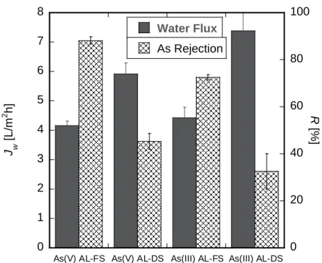
2.1.3.2 Effect of the membrane surface orientation on water flux and As rejection
Figure 2-4 shows the influence of the membrane surface orientation on Jw and R. The surface
orientation with the active layer facing the draw solution (AL-DS) exhibited higher Jw and lower
R[%] compared with the surface orientation with the active layer facing the feed solution (AL-FS).
The differences between these influences on Jw and R was attributed to internal concentration
polarization [75]. In the case of AL-DS, because water permeated from feed solution to draw solution through the porous support layer toward the active layer of the membrane, the concentration of As species diffused to the active layer insignificantly suppressed As rejection. However, in the case of AL-FS, because water permeated through the active layer to the porous support layer and diluted the draw solution in the support layer, As rejection was enhanced, and water flux was suppressed. Thus, since NaCl in the draw solution diffused toward the interface between the active layer and the porous support layer to restore the osmotic driving force, the diffusion of As species was hindered by the support layer. 0 1 2 3 4 5 6 60 65 70 75 80 85 90 95 100 3 4 5 6 7 8 9 J w As(III) Jw As(V) R As(III) R As(V) J w [L /m 2 h] R [% ] pH
20
Figure 2-4. Influence of the membrane surface orientation on the Jw and R;
[As] = 10 mg/L and [NaCl] = 1.0 mol/L.
2.2 Arsenic Removal from Aqueous Solution Using Electrodialysis 2.2.1 Introduction
Nowadays, RO represents a worldwide solution for many desalination problems, but ED could be a promisingly effective solution for many industrial applications of different size. ED with ion exchange membranes represents one of the most important membrane technology [107]. Only a few studies relating the removal of As by ED have been reported [71,108,109]. A previous research by Mendoza et al. investigating the removal of As(V) by ED process showed that removal efficiency of As(V) was more than 98% [71]. In their study, As(III) was also removed after oxidation treatment of As(III) to As(V). The similar research by Ribeiro et al. was performed by batchwise removal of As by ED from the chromated copper arsenate-treated timber waste [108]. However, the performance of ED in removing the various As species from aqueous solution in the presence of different conditions, has not yet been reported. Since the removal of As(III) and As(VI) by ED are influenced by the various factors and operation modes in order to systematically elucidate the separation mechanism, further insight into the removal of As by ED process as well as optimization of ED process should be provided.
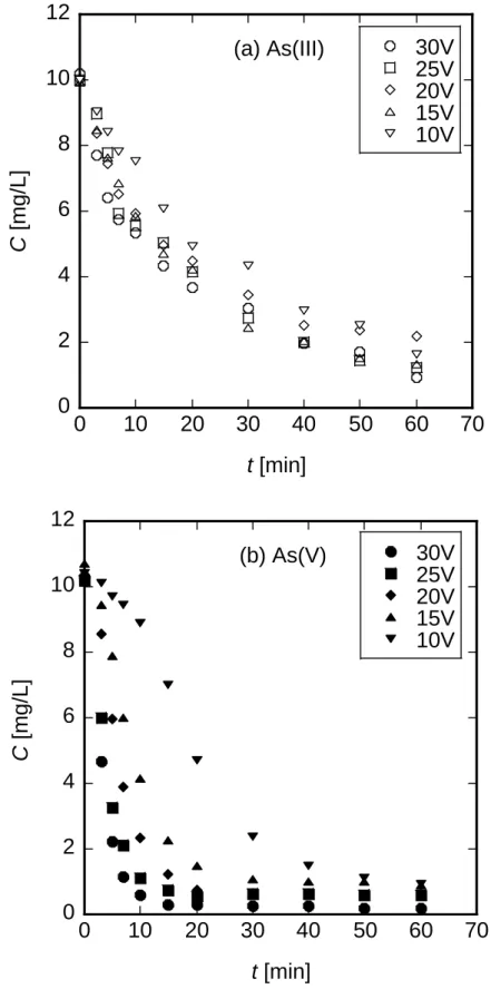
In the present work, the application potential of ED process was investigated for removal of As from aqueous solution. The influences of operational parameters, such as discharged voltage of ED, initial concentration of As and pH of the feed solution were elucidated. In addition, As removal from geothermal water by the ED process was demonstrated as a case study.
0 1 2 3 4 5 6 7 8 0 20 40 60 80 100
As(V) AL-FS As(V) AL-DS As(III) AL-FS As(III) AL-DS Water Flux As Rejection J w [L/m 2 h] R [ % ]
21
2.2.2 Experimental
All chemical reagents were purchased from Wako Pure Chemical Industries, Ltd. (Osaka, Japan). Actual geothermal water was collected at Oniyama-Jigoku in Beppu, Japan. Composition of the elements and pH are as follows: [As] = 5.03 mg/L, [Ca] = 34.3 mg/L, [K] = 176 mg/L, [Li] = 7.43 mg/L, [Mg] = 3.19 mg/L, [Na] = 101 mg/L and pH = 4.0.
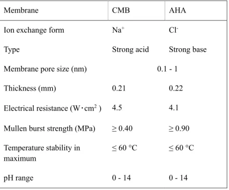
The ED experiments were carried out using an ACILYZER EX3B (ASTOM Corporation, Tokyo, Japan). The ED stack is completely assembled with a cation exchange membrane (CMB membrane), a compartment with the diluted solution, an anion exchange membrane (AHA membrane), and the concentrated compartment, comprising 10 cell pairs, and electrodes (anode: Pt/Ir-MMO coated Ti-stretched metal, cathode: stainless steel). The membrane stack was prepared in series by alternatively placing 10 anion and 11 cation exchange membranes; both the ends were connected to both the electrodes. The properties of membranes installed in the ED stack were given in Table 2-1. Spacers used between ED membranes are made of poly(vinyl chloride). The membrane area was totally 550 cm2 (55 cm2/cell).
Table 2-1. The specifications of membranes installed in ACILYZER EX3B system
Membrane CMB AHA
Ion exchange form Na+ Cl
-Type Strong acid Strong base
Membrane pore size (nm) 0.1 - 1
Thickness (mm) 0.21 0.22
Electrical resistance (W・cm2 ) 4.5 4.1
Mullen burst strength (MPa) ≥ 0.40 ≥ 0.90
Temperature stability in maximum
≤ 60 °C ≤ 60 °C
pH range 0 - 14 0 - 14
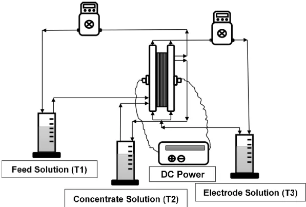
A schematic diagram of the ED apparatus is shown in Figure 2-5. The system consists of three round bottom tanks (T1, T2, and T3), one each for feed, concentrate, and electrode solutions, respectively. Each tank is connected with the pumps that are magnetically coupled and are driven by polypropylene wetted parts. A DC power supply was used to apply an external voltage in the range of 0 – 35 V. The outlet flow rate of the solution was evaluated manually by measuring the time required to fill a graduated cylinder.
![Figure 1-1. The summary of various membrane procedure applications [5].](https://thumb-ap.123doks.com/thumbv2/123deta/8003965.1250228/5.892.154.803.610.979/figure-summary-various-membrane-procedure-applications.webp)
![Figure 2-1. Relationships between J w and R[%] and [As] in the feed solution;](https://thumb-ap.123doks.com/thumbv2/123deta/8003965.1250228/21.892.239.719.133.549/figure-relationships-j-w-r-feed-solution.webp)
![Figure 2-2. Relationships between J w and R [%] and [NaCl] in the draw solution;](https://thumb-ap.123doks.com/thumbv2/123deta/8003965.1250228/22.892.249.721.135.553/figure-relationships-j-w-r-nacl-draw-solution.webp)
![Figure 2-3. Relationships between J w and R[%] and the pH of the feed solution;](https://thumb-ap.123doks.com/thumbv2/123deta/8003965.1250228/23.892.239.721.318.726/figure-relationships-j-w-r-ph-feed-solution.webp)