FACTORY AUTOMATION
MITSUBISHI CNC
NC Specification Selection Guide
M800/M80 Series
1 2
1
2
3
4
5
6
7
8
Contents
OVERVIEW
CNC LINEUP ···3
SELECTION PROCEDURE ···4
PRODUCT LINES ···5
M800/M80 SERIES LINEUP ···7
CNC SYSTEM ···9
M800/M80 SERIES SPECIFICATIONS LIST ···9
HARDWARE ···33
CONTROL UNIT/DISPLAY UNIT ···34
I/O UNIT AND OTHERS ···35
GENERAL CONNECTION DIAGRAM ···36
LIST OF CABLES ···45
DRIVE SYSTEM ···49
SYSTEM CONFIGURATION ···51
SPECIFICATIONS ···55
TYPE ···57
SERVO MOTOR/DIRECT-DRIVE MOTOR/LINEAR SERVO MOTOR 200V ···62
HG Series ···62
TM-RB Series ···65
LM-F Series ···66
SPINDLE MOTOR/ BUILT-IN SPINDLE MOTOR /TOOL SPINDLE MOTOR 200V ···68
SJ-D Series ···68
SJ-DL Series ···71
SJ-BG Series ···78
HG Series ···86
SJ-DG Series ···69
SJ-V Series ···73
SJ-B Series ···79
HG-JR Series ···86
SJ-DJ Series ···70
SJ-VL Series ···77
SJ-PMB Series ···85
HG Series ···87
SERVO MOTOR/LINEAR SERVO MOTOR 400V ···88
HG-H Series ···88
HQ-H Series ···89
LM-F Series ···90
SPINDLE MOTOR /TOOL SPINDLE MOTOR 400V ···91
SJ-4-V Series ···91
HG-JR Series ···93
DRIVE UNIT ···94
MDS-E Series ···94
MDS-EJ/EJH Series ···99
MDS-EH Series ···96
MDS-EM/EMH Series ···98
SELECTION OF THE POWER SUPPLY UNIT ···101
SELECTION OF THE ADDITIONAL AXIS DRIVE UNIT ···108
DEDICATED OPTIONS SERVO OPTIONS···113
DEDICATED OPTIONS SPINDLE OPTIONS ···118
ENCODER INTERFACE UNIT ···124
DEDICATED OPTIONS DRIVE UNIT OPTION ···126
SELECTION OF CABLES AND CONNECTORS ···132
LIST OF CABLES ···143
SOFTWARE TOOLS ···149
GLOBAL SALES & SERVICE NETWORK ···151
We bring together the best minds to
create the best technologies. At
Mitsubishi Electric, we understand
that technology is the driving force of
change in our lives. By bringing
great-er comfort to daily life, maximizing the
efficiency of businesses and keeping
things running across society, we
integrate technology and innovation to
bring changes for the better.
Through Mitsubishi Electric’s vision, “Changes for the Better“ are possible for a brighter future.
Mitsubishi Electric is involved in many areas including the following
Energy and Electric Systems
A wide range of power and electrical products from generators to large-scale displays.
Electronic Devices
A wide portfolio of cutting-edge semiconductor devices for systems and products.
Home Appliance
Dependable consumer products like air conditioners and home
entertain-ment systems.
Information and Communication Systems
Commercial and consumer-centric equipment, products and systems.
Industrial Automation Systems
Maximizing productivity and efficiency with cutting-edge automation technology.
Global Player
GLOBAL IMPACT OF
・
Separated type, a control unit
separated from display
・
Windows-based display is included
in the lineup, which provides
excellent expandability
・
Four expansion slots are provided as
standard specifications, allowing for
expansion using option card slot
Premium CNC provides
expandability and
flexibility
・
Panel-in type, a control unit with
integrated display
・
Multi-CPU architecture allows for high
performance and high functional
graphics
・
Windows-less display provides easy
operability
High-grade CNC well
suited to high-speed
high-accuracy machining
and multi-axis multi-part
system control
・
Panel-in type, a control unit with
integrated display
・
Provided in package (TypeA/TypeB)
for easier selection
・
Windows-less based display provides
easy operability
Standard CNC provides
high productivity
and easy operability
・
Separated type, a control unit
separated from display
・
Windows-based display is included in
the lineup, which provides excellent
expandability
・
Packaged type for selecting a
machine type easily
・
Two expansion slots are provided as
standard specifications, allowing for
expansion using option cards slot
Standard CNC with
expandability and flexibility
High
Performance
Standard
M800W
M80W
M800S
M80
3 4
2
SELECTION PROCEDURE
1
CNC LINEUP
CNC LINEUP
CNC LINEUP
SELECTION PROCEDURE
SELECTION PROCEDURE
Selection procedur
e flow chart
Start selecting the NC specifications!
STEP
1
Check the machine type and specifications
· Machine type: lathe / machining center / grinding machine / special-purpose machine, etc.
· Details of control, required accuracy, with/without auxiliary axes (for workpiece feeding, turret, etc.)
STEP
2
Decide the NC specifications
P7
· Number of axes, axis configuration, number of part systems, with/without spindles, number of I/O points
· Check the position detection method and detection performance (absolute/relative position, number of pulses)
· Select the size of the display unit, keyboard
STEP
3
Decide the servo motor
P62
· Select the servo motor capacity
· Check the outline dimensions, encoder, and whether it has a scale or break
STEP
4
Decide the spindle motor
P68
· Check the spindle's base/maximum rotation speed, output, torque, outline dimensions and whether it has a keyway
· Frame-type or built-in spindle motor
· With/without optional specifications (orientation, spindle/C-axis, synchronization, etc.)
· Check the C axis accuracy and the speed (when C axis is used)
STEP
5
Decide the drive unit
P94
· Check the capacity and the dimensions of a drive unit
· Check the power regeneration/resistor regeneration
STEP
6
Decide the power supply unit
P101
· Select the power supply unit only when a power regenerative drive unit is used
STEP
7
Decide the hardware options
P33,P45,P132
· Check the options
(manual pulse generator, synchronous encoder, availability of network connection and PLC connection, etc.)
· Check the required cables and connectors (In some cases, customers may need to prepare cables and connectors themselves.)
STEP
8
Decide the software options
P9
· Check the number of programs stored (memory capacity), number of variable sets, etc.
· Check the required functions
STEP
9
Check the development tools
P149
· Check the screen development tool (when screen customization is required)
5 6
1
2
3
PRODUCT LINES
1
2
3
PRODUCT LINES
Ethernet
Software
MC
AC reactor
AC power
supply
Power
supply
unit
Power
backup
unit
EcoMonitorLight
Field Network
Drive unit
Remote
I/O unit
Manual
pulse
generator
Machine
operation
panel
• NC Designer2
• NC Trainer2
• NC Trainer2 plus
• NC Explorer
• NC Monitor2
• MITSUBISHI CNC
communication software
(FCSB1224W000)
• MDS-E/EH Series
• MDS-EJ/EJH Series
• MDS-EM/EMH Series
Spindle
motor
• SJ-D Series
• SJ-DG Series
• SJ-DL Series
• SJ-BG Series
Servo motors
• HG Series
• LM-F Series
• TM-RB Series
Tool
spindle
motor
• HG Series
• HG-JR Series
PC server
• Production control system
• CC-Link
• PROFIBUS-DP
Software
• NC Analyzer2
• NC Configurator2
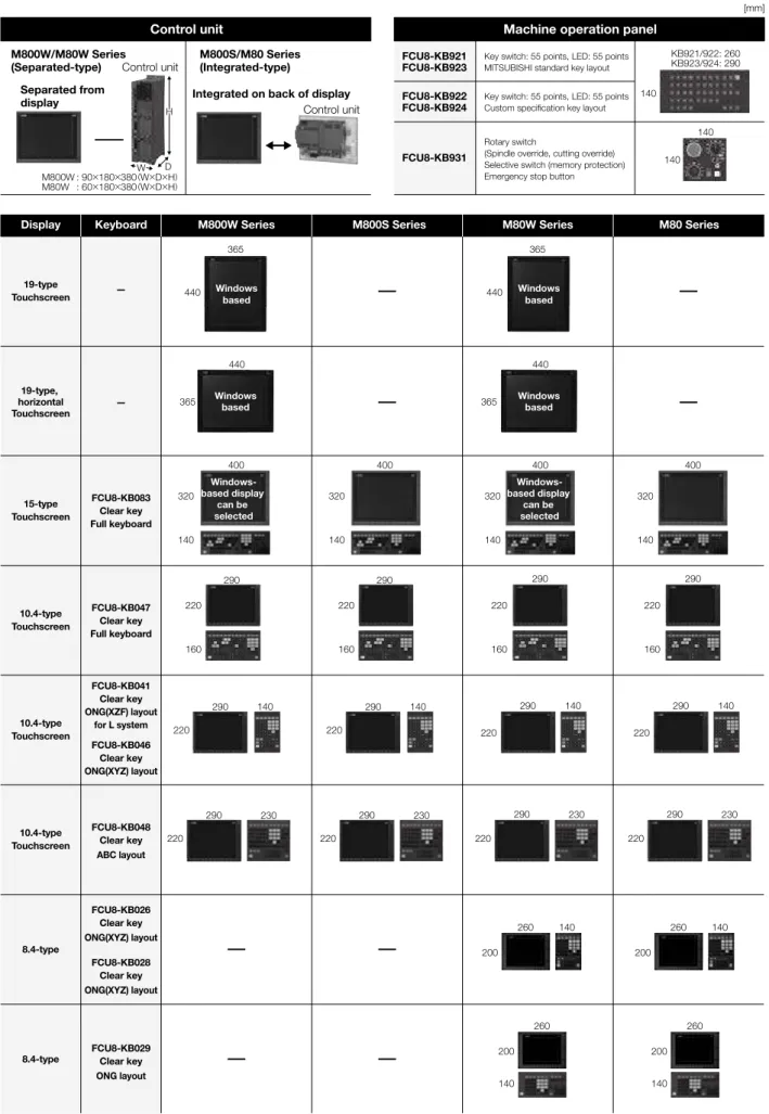
Display-integrated control unit
& Keyboard
M800S/M80 Series
SD card
USB memory
Display
& Keyboard
Control unit
M800W/M80W Series
SD card
USB memory
SD card
* Optional part
* Optional part
* Optional parts are not provided as accessories for NC equipment. Please purchase desired components from a Mitsubishi Electric dealership, etc.
User-prepared
PRODUCT LINES
PRODUCT LINES
7 8
1
2
3
4
M800/M80 SERIES LINEUP
1
2
3
4
M800/M80 SERIES LINEUP
Lathe system
(Display/Control unit separated-type)
(Display/Control unit integrated-type)
(Display/Control unit separated-type)
(Display/Control unit integrated-type)
Model name
M800W Series
M800S Series
M80W Series
M80 Series
M850W
M830W
M850S
M830S
—
TypeA
TypeB
Number of contr
ol axes
Max. number of axes
(NC axes + Spindles + PLC axes)
32
32
12
12
9
Max. number of NC axes
(in total for all the part systems)
32
32
10
10
7
Max. number of spindles
8
8
4+G/B
(*1)4+G/B
(*1)3
Max. number of PLC axes
8
8
6
6
Max. number of PLC indexing axes
8
8
4
4
Number of simultaneous
contouring control axes
8
4
8
4
4
4
Max. number of
NC axes in a part system
12
12
8
8
5
Max. number of part systems (main + sub)
8
8
4
4
2
Max. number of main part systems
8
8
2
2
2
Max. number of sub part systems
8
8
2
2
1
Control unit-side High-speed program server mode
Available
—
Available
—
Display unit-side High-speed program server mode
Available/—
(*2)Available
Available/—
(*2)Available
Front-side SD card mode
Available
Available
Available
Available
Least command increment
1nm
1nm
0.1µm
0.1µm
Least control increment
1nm
1nm
1nm
1nm
Number of tool offset sets
999
999
256
256
99
Max. program capacity
2,000kB
(5,120m)
(1,000)
2,000kB
(5,120m)
(1,000)
500kB
(1,280m)
(1,000)
500kB
(1,280m)
(1,000)
Max. PLC program capacity [steps]
512,000
512,000
64,000
64,000
32,000
Multi-project [number of PLC projects stored]
6
6
3
3
1
Interactive cycle insertion
Available
High-speed machining mode I maximum [kBPM]
33.7
33.7
33.7
33.7
—
High-speed machining mode II maximum [kBPM]
168
168
67.5
67.5
—
High-speed high-accuracy control I maximum [kBPM]
67.5
67.5
33.7
33.7
—
High-speed high-accuracy control II maximum [kBPM]
168
168
67.5
67.5
—
High-speed high-accuracy control III maximum [kBPM]
—
—
—
—
High-accuracy control
Available
—
SSS control (Super Smooth Surface)
Available
—
Tolerance control
Available
—
CC-Link (Master/Local)
Available
PROFIBUS-DP (Master)
Available
MES interface library
Available
Smart Safety observation
Available
Display unit
(*3)19-type touchscreen, 19-type horizontal
touchscreen, 15-type touchscreen, or
10.4-type touchscreen can be selected
15-type touchscreen or
10.4-type touchscreen can be
selected
19-type touchscreen, 19-type horizontal
touchscreen, 15-type touchscreen, 10.4-type
touchscreen, or 8.4-type can be selected
15-type touchscreen, 10.4-type,
touchscreen or 8.4 type can be
selected
Windows
®8 selection
(*3)Available/—
(*2)—
Available/—
(*2)—
* Maximum specifications including optional specifications are listed. Refer to the Specifications List for the details of each option.
(*1) G/B: Guide Bush
(*2) Windows-based dispaly unit/Windows-less displpay unit
(*3) For details, refer to "CNC SYSTEM CONTROL UNIT/DISPLAY UNIT" to be described.
Machining center system
(Display/Control unit separated-type)
(Display/Control unit integrated-type)
(Display/Control unit separated-type)
(Display/Control unit integrated-type)
Model name
M800W Series
M800S Series
M80W Series
M80 Series
M850W
M830W
M850S
M830S
—
TypeA
TypeB
Number of contr
ol axes
Max. number of axes
(NC axes + Spindles + PLC axes)
32
32
11
11
9
Max. number of NC axes
(in total for all the part systems)
16
16
8
8
5
Max. number of spindles
4
4
2
2
Max. number of PLC axes
8
8
6
6
Max. number of PLC indexing axes
8
8
4
4
Number of simultaneous
contouring control axes
8
4
8
4
4
4
Max. number of
NC axes in a part system
12
12
8
8
5
Max. number of part systems (main + sub)
2
2
2
2
1
Max. number of main part systems
2
2
2
2
1
Max. number of sub part systems
2
2
—
—
—
Control unit-side High-speed program server mode
Available
—
Available
—
Display unit-side High-speed program server mode
Available/—
(*2)Available
Available/—
(*2)Available
Front-side SD card mode
Available
Available
Available
Available
Least command increment
1nm
1nm
0.1µm
0.1µm
Least control increment
1nm
1nm
1nm
1nm
Number of tool offset sets
999
999
400
400
400
Max. program capacity
2,000kB
(5,120m)
(1,000)
2,000kB
(5,120m)
(1,000)
500kB
(1,280m)
(1,000)
500kB
(1,280m)
(1,000)
Max. PLC program capacity [steps]
512,000
512,000
64,000
64,000
32,000
Multi-project [number of PLC projects stored]
6
6
3
3
1
Interactive cycle insertion
—
High-speed machining mode I maximum [kBPM]
33.7
33.7
33.7
33.7
16.8
High-speed machining mode II maximum [kBPM]
168
168
67.5
67.5
High-speed high-accuracy control I maximum [kBPM]
67.5
67.5
33.7
33.7
High-speed high-accuracy control II maximum [kBPM]
168
168
67.5
67.5
High-speed high-accuracy control III maximum [kBPM]
270
270
135
135
—
High-accuracy control
Available
SSS control (Super Smooth Surface)
Available
Tolerance control
Available
CC-Link (Master/Local)
Available
PROFIBUS-DP (Master)
Available
MES interface library
Available
Smart Safety observation
Available
Display unit
(*3)19-type touchscreen, 19-type horizontal
touchscreen, 15-type touchscreen, or
10.4-type touchscreen can be selected
15-type touchscreen or
10.4-type touchscreen can be
selected
19-type touchscreen, 19-type horizontal
touchscreen, 15-type touchscreen, 10.4-type
touchscreen, or 8.4-type can be selected
15-type touchscreen, 10.4-type,
touchscreen or 8.4 type can be
selected
Windows
®8 selection
(*3)Available/—
(*2)—
Available/—
(*2)—
M800/M80 SERIES LINEUP
M800/M80 SERIES LINEUP
9 10
1
2
3
4
5
CNC SYSTEM
1
2
3
4
5
CNC SYSTEM
Standard
Optional
Selection Specifications of separated-type display are classified with “Windows-based” and “Windows-less”
S/W ver.C3
class
Lathe system
Machining center
system
Machining center system
General explanation
M800W
M800S
M80W
M80
M800W
M800S
M80W
M80
M850W
M830W
M850S
M830S
—
M80
TypeA
M80
TypeB
M850W
M830W
M850S
M830S
—
M80
TypeA
M80
TypeB
1 Control axes
1 Control axes
1 Number of basic control axes (NC axes)
2
2
2
2
2
2
2
3
3
3
3
3
3
3
The NC axis, spindle, and PLC axis are generically called the control axis. The NC axis can be manually or automatically operated using a machining program. The PLC axis can be controlled using a sequence program.
The number of axes that is within the max. number of control axes, and that does not exceed the max. number given for the NC axis, spindle and PLC axis, can be used.
2 Max. number of axes (NC axes + Spindles + PLC axes)
16
32
16
32
16
32
16
32
12
12
9
16
32
16
32
16
32
16
32
11
11
9
Max. number of NC axes
(in total for all the part systems)
16
32
16
32
16
32
16
32
10
10
7
16
16
16
16
8
8
5
Max. number of spindles
8
8
8
8
4+G/B
4+G/B
3
4
4
4
4
2
2
2
Max. number of PLC axes
8
8
8
8
6
6
6
8
8
8
8
6
6
6
4 Max. number of PLC indexing axes
8
8
8
8
4
4
4
8
8
8
8
4
4
4
The number of PLC axes available to be used as indexing axis.5 Number of simultaneous contouring control axes
8
4
8
4
4
4
4
8
4
8
4
4
4
4
Number of axes with which simultaneous interpolation control is possible.6 Max. number of NC axes in a part system
8
12
8
12
8
12
8
12
8
8
5
8
12
8
12
8
12
8
12
8
8
5
Max. number of NC axes possible to control in the same part system.7 Axis name extension
The axis name (command axis name) to issue the absolute/incremental value command to NC control axis can be expanded to two letters.2 Control part system
1 Standard number of part systems
1
1
1
1
1
1
1
1
1
1
1
1
1
1
One part system is the standard.2 Max. number of part systems (main + sub)
4
8
4
8
4
8
4
8
4
4
2
2
2
2
2
2
2
1
Up to eight part systems for a lathe system, and up to two part systems for a machining center system.
Max. number of main part systems
4
8
4
8
4
8
4
8
2
2
2
2
2
2
2
2
2
1
Max. number of sub part systems
4
8
4
8
4
8
4
8
2
2
1
2
2
2
2
—
—
—
3 Control axes and operation modes
1 Tape (RS-232C input) mode
In this mode, operation is performed using the machining program data from the RS-232C interface built in the CNC unit.2 Memory mode
Machining programs stored in the memory of the CNC module are run.3 MDI mode
MDI data stored in the memory of the CNC unit are executed.4 High-speed program server mode
1 Control unit-side High-speed program server mode
—
—
—
—
—
—
—
—
The machining program stored in SD card can be operated by installing a SD card in the control unit SD card interface.2 Display unit-side High-speed program server mode
/—
/—
/—
/—
/—
/—
The machining program stored in the built-in disk of the display unit can be operated.
The built-in disk of the display unit is mounted in the personal computer for M800W/M80W (Windows-based display unit). For M800S/M80, the SD card inserted into SD card I/F on the back of the display unit is equivalent to the built-in disk of the display unit.
5 Front-side SD card mode
The machining program stored in a SD card can be operated. This SD card is installed to the front-side SD card I/F.6 Front-side USB memory mode
The machining program stored in a USB memory can be operated. This USB memory is installed to the front-side USB memory I/F.2 Input command
1 Data increment
1 Least command increment
The data increment handled in the controller includes the input setting increment and command increment. Each type is set with parameters.Least command increment 1µm
Possible to command in increments of 0.001mm (linear axis) and 0.001° (rotary axis).Least command increment 0.1µm
Possible to command in increments of 0.0001mm (linear axis) and 0.0001° (rotary axis).Least command increment 0.01µm (10nm)
—
—
—
—
—
—
Possible to command in increments of 0.00001mm (linear axis) and 0.00001° (rotary axis).Least command increment 0.001µm (1nm)
—
—
—
—
—
—
Possible to command in increments of 0.000001mm (linear axis) and 0.000001° (rotary axis).2 Least control increment
The least control increment determines the CNC's internal operation accuracy.Least control increment 0.01µm (10nm)
Possible to control in increments of 0.00001mm (linear axis) and 0.00001° (rotary axis).Least control increment 0.001µm (1nm)
Possible to control in increments of 0.000001mm (linear axis) and 0.000001° (rotary axis).3 Indexing increment
This function limits the command value for the rotary axis.2 Unit system
1 Inch / Metric changeover
The unit systems of the data handled in the controller include the metric system and inch system. The type can be designated with a parameterand a machining program.
2 Input command increment tenfold
—
—
—
—
—
—
—
The program's command increment can be multiplied by an arbitrary scale with the parameter designation. This function is valid when a decimalpoint is not used for the command increment.
3 Program format
1 Program format
G code (program) format1 Format 1 for Lathe (G Code List 2, 3)
—
—
—
—
—
—
—
G code list for the lathe system. The G code list is selected by parameter.
2 Format 2 for Lathe (G Code List 4, 5)
—
—
—
—
—
—
—
3 Special format for lathe (G Code List 6, 7)
—
—
—
—
—
—
—
4 Format 1 for Machining center
—
—
—
—
—
—
—
G code list for the machining center system. The G-code list is selected by parameter.
5 Format 2 for Machining center (M2 format)
—
—
—
—
—
—
—
6 MITSUBISHI CNC special format
—
—
—
—
—
—
—
The formats of the fixed cycle for turning machining (G77 to G79), compound type fixed cycle for turning machining (G71 to G76) and fixed cycle for drilling (G80 to G89) can be switched to the MITSUBISHI CNC special formats.2 Program format switch
—
—
—
—
—
—
—
—
—
—
This function is designed to switch the program format (G code list) using G codes or PLC signal. When you run a lathe-based multi-tasking machine, and if you change to the G code list of machining center system, you can use a free-curved surface machining program made with CAM without modifying the program.4 Command value
1 Decimal point input
1
,
2
For the decimal point input type 1, the unit of the last digit of a command without a decimal point is the same as that of the least command increment. For decimal point input type 2, the last digit of a command without a decimal point is interpreted in millimeters during the metric mode, in inches in the inch mode, or in seconds for a time-based command.
2 Absolute / Incremental command
When axis coordinate data are issued in a machining program command, either the incremental command method, which commands a relative distance from the current position, or the absolute command method, which commands a movement to a designated position in a predetermined coordinate system, can be selected.
3 Diameter / Radius designation
—
—
—
—
—
—
—
The designation method of an axis command value can be changed over with parameters between the radius designation or diameter designation. When the diameter designation is selected, the scale of the length of the selected axis is doubled. (moves only half (1/2) the commanded amount)3 Positioning / Interpolation
1 Positioning
1 Positioning
This function carries out positioning at high speed using a rapid traverse rate with the travel command value given in the program.2 Unidirectional positioning
—
—
—
—
—
—
—
The G code command always moves the tool to the final position in the direction determined by parameters.2 Linear / Circular interpolation
1 Linear interpolation
Linear interpolation is a function that moves a tool linearly by the travel command value supplied in the program at the cutting feedrate designatedby the F code.
2 Circular interpolation (Center / Radius designation)
This function moves a tool along a circular arc on the plane selected by the travel command value supplied in the program.3 Helical interpolation
With this function, any two of three axes intersecting orthogonally are made to perform circular interpolation while the third axis performs linearinterpolation in synchronization with the arc rotation. This control can be exercised to machine large-diameter screws or 3-dimensional cams.
4 Spiral / Conical interpolation
—
—
—
—
—
—
—
—
This function interpolates arcs where the start point and end point are not on the circumference of the same circle into spiral shapes.5 Cylindrical interpolation
This function transfers the shape that is on the cylinder's side surface (shape yielded by the cylindrical coordinate system) onto a plane, and when the transferred shape is designated in the program in the form of plane coordinates, the shape is converted into a movement along the linear and rotary axes of the original cylinder coordinates, and the contours are controlled by means of the CNC unit during machining.
M800/M80 SERIES SPECIFICATIONS LIST
M800/M80 SERIES SPECIFICATIONS LIST
CNC SYSTEM M800/M80 SERIES SPECIFICATIONS LIST
11 12
1
2
3
4
5
CNC SYSTEM
1
2
3
4
5
CNC SYSTEM
Standard
Optional
Selection Specifications of separated-type display are classified with “Windows-based” and “Windows-less”
S/W ver.C3
class
Lathe system
Machining center
system
Machining center system
General explanation
M800W
M800S
M80W
M80
M800W
M800S
M80W
M80
M850W
M830W
M850S
M830S
—
M80
TypeA
M80
TypeB
M850W
M830W
M850S
M830S
—
M80
TypeA
M80
TypeB
6 Polar coordinate interpolation
—
—
—
This function converts the commands programmed by the orthogonal coordinate axes into linear axis movements (tool movements) and rotary axis movements (workpiece rotation) to control the contours. It is useful for cutting linear cutouts on the outside diameter of the workpiece, grinding cam shafts, etc.
7 Milling interpolation
—
—
—
—
—
—
—
When a lathe with linear axes (X, Z axes) and rotary axis (C axis) serving as the control axes is to perform milling at a workpiece end face or in the longitudinal direction of the workpiece, this function uses the hypothetical axis Y, which is at right angles to both the X and Z axes, to enable the milling shape to be programmed as the X, Y and Z orthogonal coordinate system commands.
8 Hypothetical axis interpolation
—
—
—
—
—
—
—
—
—
—
This function sets one of the axes of the helical interpolation or spiral interpolation, including a linear axis, as a hypothetical axis (axis with no actual movement), and performs pulse distribution. This enables SIN or COS interpolation, which corresponds to the side view (view from the hypothetical axis) of the helical interpolation or spiral interpolation.
3 Curve interpolation
1 Involute interpolation
—
—
—
—
—
—
—
—
Tools can be moved along the involute curve. This can be used for scroll machining of involute gears or compressors, and smooth accurate machining can be performed without stepping of path from the command by fine segment or without acceleration/deceleration by segment length.2 Exponential interpolation
—
—
—
—
—
—
With this function, the rotary axis movement is changed into exponential functions vis-a-vis the linear axis movements.3 Spline interpolation (G05.1Q2 / G61.2)
—
—
—
—
—
—
—
—
This function automatically generates spline curves that smoothly pass through rows of dots designated by a fine-segment machining program, and performs interpolation for the paths along the curves. This enables high-speed and high-accuracy machining.4 NURBS interpolation
—
—
—
—
—
—
—
—
—
—
This function realizes NURBS curve machining by commanding NURBS curve parameters (number of stages, weight, knot, control point). The path does not need to be replaced with fine segments.5 3-dimensional circular interpolation
—
—
—
—
—
—
—
—
—
—
An arc shape determined by three points (start point, intermediate point, end point) designated in the three-dimensional space can be machined.6 Spline interpolation2 (G61.4)
—
—
—
—
—
—
—
—
This function automatically generates curves that smoothly pass in the tolerance error range, and moves on the paths along the curves. This enables smooth machining.4 Feed
1 Feedrate
1 Rapid traverse rate (m/min)
1000
1000
1000
1000
1000
1000
1000
1000
1000
1000
1000
1000
1000
1000
The rapid traverse rate can be set independently for each axis using parameters.2 Cutting feedrate (m/min)
1000
1000
1000
1000
1000
1000
1000
1000
1000
1000
1000
1000
1000
1000
This function specifies the feedrate of the cutting commands, and gives a command for a feed amount per spindle rotation or feed amount per minute.3 Manual feedrate (m/min)
1000
1000
1000
1000
1000
1000
1000
1000
1000
1000
1000
1000
1000
1000
The manual feedrates are designated as the feedrate in jog mode or incremental feed mode for manual operation and the feedrate during dry run ON for automatic operation. The manual feedrates are set using external signals.4 Rotary axis command speed tenfold
This function multiplies the rotary axis' command speed by ten during initial inching.2 Feedrate input methods
1 Feed per minute (Asynchronous feed)
By issuing a G command, the command from the block is issued directly with a numerical value following F as the feedrate per minute (mm / min orinch / min).
2 Feed per revolution (Synchronous feed)
By issuing a G command, the command from the block is issued directly with a numerical value following F as the feedrate per spindle revolution (mm/ rev or inch / rev).
3 Inverse time feed
—
—
—
—
—
—
—
—
This function can issue one block of machining time (inverse) commands in F commands, in place of normal feed commands. This enables the machining speed on the cutting surface to be constantly controlled and prevents the loss of accuracy, even if radius compensation is applied to the machining program that expresses the free curve surface with fine segment lines.
4 F 1-digit feed
The feedrate registered by parameter in advance can be assigned by designating a single digit, following address F.5 Manual speed command
By enabling a manual speed command and selecting either handle feed or jog (manual) feed in the memory or MDI mode, automatic operation canbe carried out at this feedrate.
7 G00 feedrate designation (,F command)
—
—
Feedrates can be specified for G00 (positioning command).
The speed of tool exchange, axis movement of gantry, etc. can be specified with the machining program so that the mechanical vibration can be suppressed.
3 Override
1 Rapid traverse override
Override can be applied to manual or automatic rapid traverse using the external input signal.2 Cutting feed override
Override can be applied to the feedrate command designated in the machining program using the external input signal.3 2nd cutting feed override
Override can be further applied as a second-stage override to the feedrate after the cutting feed override has been applied.4 Override cancel
By turning on the override cancel external signal, the override is automatically set to 100% for the cutting feed during the automatic operation mode(tape, memory and MDI).
4 Acceleration / Deceleration
1 Automatic acceleration / deceleration after interpolation
Acceleration / deceleration is automatically applied to all commands. The acceleration / deceleration patterns can be selected using a parameter from the following types: linear acceleration/deceleration, soft acceleration / deceleration, exponent function acceleration / deceleration and exponent function acceleration / linear deceleration.
2
Rapid traverse constant inclination acceleration /
deceleration
This function performs acceleration / deceleration at a constant inclination during linear acceleration / deceleration in the rapid traverse mode. Compared to the method of acceleration / deceleration after interpolation, the constant inclination acceleration / deceleration method enables improved cycle time.
3
Rapid traverse constant inclination multi-step acceleration /
deceleration
—
—
—
—
—
—
—
This function carries out the acceleration / deceleration according to the torque characteristic of the motor in the rapid traverse mode during automatic operation. (This function is not available in manual operation.) The rapid traverse constant inclination multi-step acceleration / deceleration method makes for improved cycle time because the positioning time is shortened by using the motor ability to the maximum.
5 Thread cutting
1 Thread cutting (Lead / Thread number designation)
Thread cutting with a designated lead can be performed. Inch threads are cut by designating the number of threads per inch with the E address.2 Variable lead thread cutting
—
—
—
—
—
—
—
By commanding the lead increment/decrement amount per thread rotation, variable lead thread cutting can be performed.3 Synchronous tapping
* With digital I/F spindle1 Synchronous tapping cycle
This function performs tapping through synchronized control of the spindle and servo axis. This eliminates the need for floating taps and enablestapping to be conducted at a highly accurate tapping depth.
2 Pecking tapping cycle
The load applied to the tool can be reduced by designating the depth of cut per pass and cutting the workpiece to the hole bottom with a multiplenumber of passes.
3 Deep-hole tapping cycle
In the deep-hole tapping, the load applied to the tool can be reduced by designating the depth of cut per pass and cutting the workpiece to thehole bottom with a multiple number of passes.
4 Chamfering
—
—
—
—
—
—
—
Chamfering can be enabled during the thread cutting cycle by using external signals.6 Circular thread cutting
—
—
—
—
—
—
—
—
Circular thread in which the lead is in longitudinal direction can be cut.8 High-speed synchronous tapping (OMR-DD)
The servo axis directly detects and compensates the spindle's delay in tracking by using the communication between drive units over thehigh-speed optical servo network. By minimizing the synchronization error, the accuracy of the synchronous tapping is increased.
10 Thread recutting
—
—
—
—
—
—
—
—
The function stores a thread groove position and compensates a start position of spindle thread cutting automatically so that the tool can passalong the memorized position of the thread groove at the thread cutting execution.
11 Thread cutting override
—
—
—
—
—
—
—
—
The thread cutting feedrate can be changed by changing the spindle override depending on rough cutting, finish machining, etc.12 Variable feed thread cutting
—
—
—
—
—
—
—
—
This function changes the cutting feedrate by the spindle override at the time of the thread cutting. The machining condition during thread cutting can be changed.13 Thread cutting time constant switch
"Thread cutting time constant" can be applied to the acceleration/deceleration time constant of the NC control axis during the tread cutting.6 Manual feed
1 Manual rapid traverse
The tool can be moved at the rapid traverse rate for each axis separately. Override can also be applied to the rapid traverse rate by means of therapid traverse override function.