Untestable Fault Identification in Sequential Circuits Using Model-Checking
Jaan Raik
1Hideo Fujiwara
2Raimund Ubar
1Anna Krivenko
11
Department of Computer Engineering,
Tallinn University of Technology,
Raja 15, 12618 Tallinn, Estonia
{jaan | raiub | anna}@pld.ttu.ee
2
Graduate School of Information Science,
Nara Institute of Science and Technology,
Kansai Science City, Nara, Japan
[email protected]
Abstract
Similar to test pattern generation, the problem of identifying untestable faults in sequential synchronous circuits remains unsolved. The previously published works in untestability identification operate at the logic-level and, thus, they do not scale with the increasing complexity of modern designs. Current paper proposes applying model-checking for detecting untestable stuck-at faults at the register-transfer level. In particular, we present a method of generating PSL language assertions for proving untestable register stuck-on faults. Experiments show that the faults identified by the method form in fact a large subset of all the untested stuck-at faults. An additional application of the method is in high-level test synthesis, where testability of sequential designs can be improved simultaneously with minimization of the circuit area. Furthermore, identification of untestable gate-level faults from RT-level can contribute to avoiding over testing and to reducing yield loss.
1. Introduction
Test generation for sequential synchronous designs is a time-consuming task. Automated Test Pattern Generation (ATPG) tools spend a lot of effort not only for deriving test vectors for testable faults but also for proving that there exist no tests for the untestable faults. Because of this reason, the identification of untestable faults has been an important aspect in speeding up the sequential ATPG. The methods proposed previously are based on performing static and dynamic implications at the logic-level. Current paper presents an approach that takes the problem of identifying untestable faults one step further: to the higher abstraction levels. We show that it is possible to very quickly find a large subset of all untestable faults before handing the untestability identification over to classical, logic-level methods.
A number of works have been proposed in order to tackle the problem of untestability identification. The first methods [1] were fault-oriented and based on applying combinational ATPG to the expanded time- frame model of the sequential circuit. However, such approach does not scale because of the size-explosion of the unrolled sequential models. Thus, the fault independent method was introduced by Iyer et al. in [2]. The new algorithm was called FIRES and it implemented illegal state information to complement redundancy analysis. This was followed by a number of fault independent methods including MUST [3], FUNI [4], FILL [4] and others. Liang [5] proposed a simulation based approach for sequential untestable fault identification. However, it was shown in [4] that this method may result in ‘false positives’, i.e. a fault may be declared untestable when there actually exists a test for it. The common limitation of the above methods is that they operate at the logic-level representation of the design. Thus a considerable amount of effort is put on the implication process carried out at the level of logic netlists.
In their previous work [6], the authors introduced a new subclass of untestable faults, called register enable stuck-on faults. However, the paper did not propose any formal method for identifying untestable register faults. In this paper we present a new method that is capable of identifying such type of untestable faults. We propose using model-checking for detecting untestable stuck-at faults at the Register-Transfer Level (RTL). In particular, we present a method for formally generating PSL language assertions for proving untestable stuck-at faults in sequential synchronous designs.
The paper is organized as follows. Section 2 gives the general motivation for targeting register enable stuck-on faults. Section 3 defines the RTL architecture. In Section 4, sufficient conditions for proving untestable registers are introduced. Section 5 presents 17th Asian Test Symposium
17th Asian Test Symposium
the implementation of the untestability identification method based on Cadence IFV model-checker. Finally, experimental results and conclusions are provided.
2. Motivation for targeting register faults
A special case of datapaths where register enable signals are redundant is a pipeline. In pipelines data is transported during each clock-cycle and therefore the registers should be constantly enabled. Enable signals in pipelines are normally omitted and the registers are replaced by buffers consisting of D-flipflops.
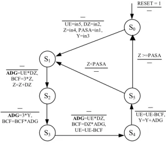
However, there are other cases than pure pipelines, where the redundancy of enable signals is much more difficult to identify. Consider for example the Extended Finite State Machine (EFSM) representation of the Differential Equation (diffeq) benchmark shown in Fig. 1. In this kind of EFSM description, the nodes represent control states and the arrows represent transitions between the states. Shown on the transitions are the enabling functions (on top of the line), i.e. conditions that enable the state transition, and the update functions (below the line) that correspond to datapath register assignments.
Figure 1. EFSM of the Diffeq benchmark Let us focus on register ADG (marked bold in Fig. 1). It can be seen that this register reads during transitions s1→s2, s2→s3, s3→s4. It can also be seen that ADG is in turn an input for two other registers: BCF and Y (shown by grey background). The latter read ADG only during transitions s2→s3, s3→s4, s4→s5. Now let us assume that the enable signal of register ADG is permanently stuck on. In that case, ADG may read faulty values except between the state
transitions s1...s4 when it is also enabled in the fault- free circuit. Note however that ADG is read always one transition later, i.e. between s2...s5. Thus, only fault-free values can be read from ADG and the stuck- on fault of its enable signal is untestable. On the other hand, as an opposite example, enable in register DZ is testable because DZ is read at s1→s2 but DZ reads no value during one of the preceeding transitions: s5→s1. The goal of current paper is to introduce a formal technique for identifying such kind of untestable stuck- at faults from the RT-level. The method presented in this paper not only allows untestable fault identification but it can also be implemented in high- level test synthesis [7-9]. Experiments show that by removing the redundant enable signals around 2 to 6 per cent of the circuit area is minimized. Furthermore, identification of untestable gate-level faults from RT- level can contribute to reducing the yield loss.
In the following, conditions that are sufficient for identifying untestable faults in register enables are introduced. Later on we implement the untestable fault analysis relying on standard model-checking tools. Finally, we carry out experiments on RTL benchmarks in order to assess the relevance of register enable faults among the untestable faults in sequential designs and evaluate the efficiency of the proposed method in untestability identification.
3. Register-transfer level architecture
Let us first consider the general architecture of register-transfer level (RTL) circuits. In RTL descriptions the design is partitioned into a control part (FSM) and a datapath part. The latter consists of registers R, multiplexers M and functional units (FUs) F. The former includes a state register for preserving the control state sj from the set of states S. The set of control signals C enter from the control part into the datapath and are partitioned to register enable signals E and multiplexer address selects A. The control signals C=E∪A are determined by the current control state sj∈S. The status bits B enter from the datapath into the control part FSM. These signals represent the results of comparison FUs and they facilitate the selection of state transitions in the FSM.
When a behavioral or behavioral RTL circuit is synthesized into RTL then the following two main steps are carried out by the high-level synthesis tool: 1) allocation of time-steps for operations, 2) binding of operations and variables into hardware resources: FUs, registers and multiplexers. Depending on the constraints given to the synthesis tool it may try to bind several operations into the same FU or a number of variables into the same register. At different time- S2
S3 S4
S5
RESET = 1
―
S0
S1
― UE=in5, DZ=in2, Z=in4, PASA=in1,
Y=in3
― ADG=UE*DZ,
BCF=3*Z, Z=Z+DZ
Z >=PASA Z<PASA ―
―
― ADG=3*Y, BCF=BCF*ADG
― ADG=UE*DZ, BCF=DZ*ADG,
UE=UE-BCF
― UE=UE-BCF,
Y=Y+ADG
steps registers obtain values from different sources (other registers, FUs or primary inputs). Thus, multiplexers to be controlled by the control part are created to select the correct source at each moment.
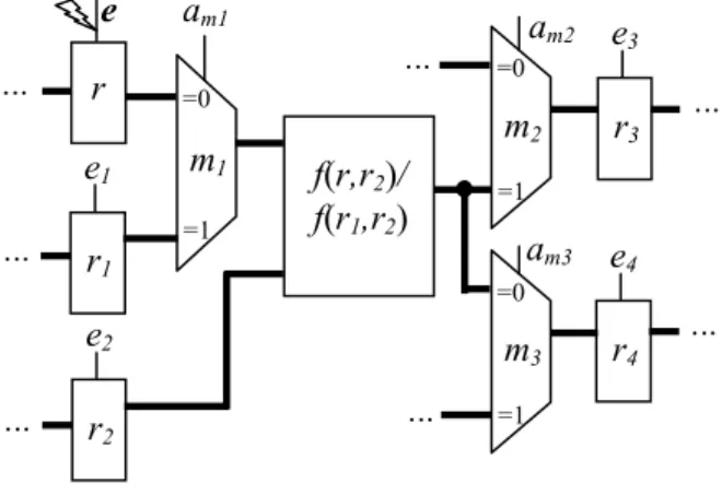
The general case for RTL datapaths is thus, a mux- operation-mux-register form (See example in Fig. 2). In other words, when moving from one register rsrc∈R to register rdst we may pass through an FU f∈F whose inputs may be selected by multiplexers Min⊂M and we
may also need an additional multiplexer mout∈M to allow the target register rdst read from different sources. Reading new data into registers ri∈R is
controlled by the control part FSM via register enable signals ei∈E. Enable signals ei are activated (i.e. ei=1) only when the corresponding registers ri perform a new read operation, otherwise the enable is deactivated (ei=0). Register may also include a global reset input.
Selecting between different sources is controlled by the multiplexers mk∈M whose address signals ak∈A enter from the control part. During these states when register reads new data its multiplexer address value is specified to select the correct source. At any other state the value of the mux address is normally unspecified and this fact makes the untestability analysis of gate- level stuck-at faults from the RT-level difficult and pessimistic. However, in the following Section we propose a property, which allows identification of a large number of untestable faults without knowing the exact logic implementation of the control part.
Figure 2. RTL datapath fragment
4. Identifying untestable registers
In this Section, we present a property for proving untestable register stuck-on faults implementing a commercial model-checking engine. The analysis is carried out at the register transfer level, and the testability of control signals is formally calculated.
Let us introduce some preliminary definitions. Definition 1: For any datapath register r the registers ri whose inputs are reachable from r through combinational logic (multiplexers and FUs) are refered to as the guarding registers of register r. For example, the guarding registers of register r in Figure 2 are r3
and r4. Note, that with the presence of feedback loops register r itself may belong to its guarding registers ri. Definition 2: If the address signals ak of multiplexers mk are set to values that activate a path between two datapath registers r1 and r2 we say that the path activation condition between r1 and r2 holds and denote it by αr1,r2=1. Otherwise, αr1,r2=0.
For example, in Figure 2 the path between registers r and r3 is selected only if the mux address signals am1=0 and am2=1. Thus, αr,r3=am1·am2.
Definition 3: Let us refer to the set of states from where a control state sj∈S can be reached within one clock-cycle as immediately preceding states of sj. Let us denote immediately preceding states of sj by prev(sj).
Throughout this paper we use the superscript notation to show at which state the signal values will be considered. For example, the value of a datapath signal v at the state sj is denoted by vsj.
Theorem 1: Let e be an enable signal controling a datapath register r, let sj, j=1,...,n, n=|S| be the set of control states and ri, i=1,...,m be the set of guarding registers for r.
If , ( )
... 1 ... 1
j j
i
j s prevs
r r s i m i n j
e
e ⋅ →
∀
∀
=
=
α
then the registerenable signal e stuck-at-1 fault is untestable.
In other words, the sufficient condition for untestability of the fault e stuck-at-1 is that for all the states sj where a guarding register ri (enabled by ei) is reading from r (enabled by e) all the immediatly preceding states of sj write values to r.
Proof: If a faulty value from register r is to be propagated to any observable output then it has to be transported via one of the guarding registers ri. Any guarding register ri can read the fault value only at those states sj where eisj= 1. Thus, at the states where
sj
ei = 0 the faulty value of r can not propagate. Furthermore, if the enable signal ei of ri is activated then exactly one activation condition αr*,ri , where r* is r or any other register that can be read by ri, must be equal to 1 (See Section 3 for the definition of RTL architecture!). It is clear that if r* is not r then the faulty value will not propagate to ri at the current state sj. Thus, the prerequisite for fault propagation to a guarding register ri at the state sj is ei·αr,ri=1.
e
r e1
r1
am1
m1 f(r,r
2)/ f(r1,r2) ...
...
=0
=1
e2
r2
...
am2
m2
=0
=1
am3
m3
=0
=1
e3
r3
e4
r4
... ...
...
...
However, if this prerequisite is fulfilled but the register r is enabled at all the states prev(sj) then it will contain only the fault-free value at prev(sj). Thus, the fault e stuck-at-one can not be tested. ■
Note, that the property for register untestability identification introduced in Theorem 1 is only a sufficient condition for the register to be untestable. There may exist untestable register enables that do not match this condition and therefore the property is somewhat pessimistic. However, its main advantage lies in the ease of computation by formal algorithms. Experimental analysis presented in Section 6 shows that in practice the method is well capable of proving untestability in different sequential benchmarks. It is also important to stress that all register enables identified by Theorem 1 are always stuck-at untestable at the logic-level.
5. Reducing untestability identification to
model-checking
This Section will discuss the technical implementation of the RTL untestable fault identification method in VHDL and PSL using Cadence IFV 05.50 model-checker. We forwarded the condition from Theorem 1 to the model-checker. If the model-checker formally proves that the condition always holds for a register r then it can be concluded that the stuck-at-1 fault of its enable signal e is untestable.
The following VHDL code with embedded PSL constructs was generated and included to the VHDL architecture description of the Design Under Test (DUT) for untestability identification of register r:
PROPERTIES: if (ABV_ON) generate begin
write_event_<r> <= <ei·αr,ri> ;
read_event_buffer: process
begin
wait until clock'event and clock = '1' ; read_event_<r> <= <e> ;
end process read_event_buffer ;
-- psl ASSERT_PSL_CHECK_<r> :
-- assert always write_event_<r> -> read_event_<r> -- abort(reset);K
end generate PROPERTIES;
The VHDL signal write_event_<r> was introduced. The signal will be equal to one when some guarding register reads from r. A dedicated VHDL process read_event_buffer was introduced to detect
the time-steps when fault-free values are read to r during the previous clock-cycle. Note, that the value of
read_event_<r> is equal to e but there is a one cycle delay betweeb them. It has been introduced in order to simplify the PSL assertion ASSERT_PSL_CHECK_<r> by allowing a combinational property (implication) to be checked.
There are special cases of registers, which are guarded not only by other datapath registers and thus, the signal write_event_<r> must be treated differently. For registers that are inputs for FUs that generate status bits B the signal write_event_<r> is assigned to value one during those states when B is read by the control part for selecting between alternative state transitions. Moreover, for registers connected to the primary outputs of DUT
write_event_<r> must be constantly tied to one.
6. Impact of register faults at the gate-level
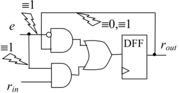
Let us consider the impact of an untestable register enable stuck-on fault at the gate-level. Fig. 3 presents a typical gate-level implementation of a single bit in a datapath register. The arrows mark the untestable stuck-at faults in the register rwhose enable signal e is untestable. As it can be seen, an untestable register enable causes four additional stuck-at signals to be untestable in a register implementing and-or multiplexers. Thus a total number of untestable lines in a register with untestable enable signal is 4n + 1 (Four faults per bit plus the fanout stem of the enable e). In the case of 32-bit register the number of untestable stuck-at faults caused by a register stuck-on fault is as high as 129. Experimental results presented in the following Section show that a large subset of all the stuck-at faults not covered by the sequential ATPG belong in fact into this particular class of faults.
Fig. 3. Gate-level impact of untestable e ≡ 1
e
r
inr
out≡1
≡1
≡0,≡1
DFF
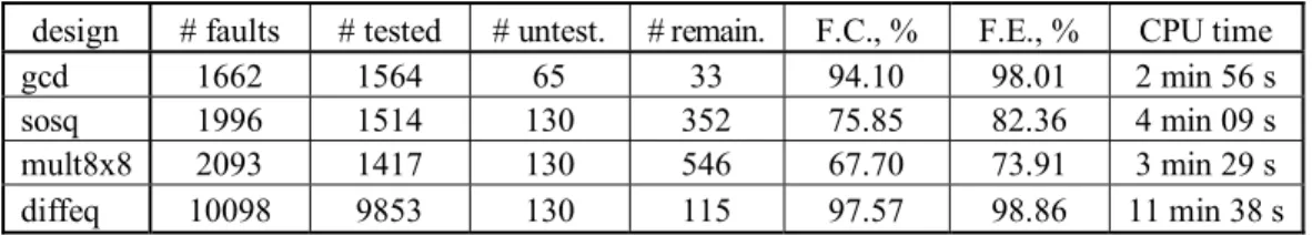
Table 1. Experimental results on identification of untestable faults
design # faults # tested # untest. # remain. F.C., % F.E., % CPU time
gcd 1662 1564 65 33 94.10 98.01 2 min 56 s
sosq 1996 1514 130 352 75.85 82.36 4 min 09 s
mult8x8 2093 1417 130 546 67.70 73.91 3 min 29 s
diffeq 10098 9853 130 115 97.57 98.86 11 min 38 s
7. Experimental results
In Table 1, untestable fault identification experiments on four sequential designs are presented. The benchmarks were chosen from the HLSynth92 and HLSynth95 families and they were synthesized to RT- level from behavioral VHDL descriptions using the high-level synthesis tool SYNT from Synthesia. Subsequently, the RTL descriptions were synthesized to logic-level by Synopsys Design Compiler. The same tool was applied for estimating the circuit area minimization by removal of untestable register enables.
Untestable fault identification was carried out with Cadence IFV model-checker on a SUN Sun-blade 100 Workstation with single 500 MHz UltraSPARC-IIe processor, 500 MB RAM, Solaris 2.9 OS. The circuits were tested by two sequential ATPG tools: a simulation based ATPG SBGEN [10] and a hierarchical ATPG DECIDER [11].
The union of the faults covered by the two test generators was chosen as the number of detected faults (column ‘# tested’) in Table 1. Column ‘# faults’ shows the total number of stuck-at faults in the circuits. Column ‘# untest.’ shows the number of untestable register enable faults identified by the method proposed in this paper. Column “# remain.” shows the number of faults that were neither tested nor identified untestable. Columns ‘F.C.’ and ‘F.E.’ present the achieved fault coverage and fault efficiency (i.e. test coverage), respectively. Finally, column ‘CPU time’ gives the CPU run times for the untestability identification.
As it can be seen from Table 1, a large number of untestable faults has been identified by the method in a relatively short run time. This fact is also supported by the statistics presented in Table 2, which shows that roughly 20-60 per cent (in average 41 %) of the faults not tested in the given benchmark circuits fall into the category of untestable register enable faults. An additional benefit of the approach is the increase in fault efficiency. Identification of untestable faults allows raising the confidence in the test coverage and in the efficiency of the ATPG.
Table 2. Core benefits of the method
gcd sosq mult diffeq average
% untestable from all not tested faults
66.3 27.0 19.2 53.1 41.4 Increase in
fault efficiency,
%
3.91 6.51 6.21 1.29 4.48 Circuit area
minimization,
%
4.70 6.51 6.31 2.12 4.91
Last but not least, untestable fault identification may also be implemented in high-level test synthesis. The last row in Table 2 shows that by removing the redundant enable signals around 2 - 6 per cent of the circuit area is minimized. Furthermore, as mentioned before, identification of untestable gate-level faults can contribute to reducing yield loss.
8. Conclusions
The paper proposed a new method for identification of untestable logic-level stuck-at faults from the register transfer level. The novelty of the approach lies in using an existing commercial model-checking tool for the untestability analysis. In particular, a technique for formally generating PSL language assertions for proving untestable stuck-at faults in sequential synchronous designs was developed. Experiments on well-known sequential benchmarks showed that as much as 20-60 per cent of faults not detected by sequential ATPG were identified untestable in a short run time by the approach.
The proposed untestable fault identification may also be implemented in high-level test synthesis. It was shown that by removing the redundant enable signals in average 5 per cent of the circuit area could be saved. An additional effect of the identification of untestable register enable faults lies in reducing yield loss.
Acknowledgements
The research has been supported partly by EC FP 6 research project VERTIGO, Enterprise Estonia funded ELIKO Development Center, Estonian SF grant 7068, 7483, Estonian Center of Excellence program, EC REGPOT program and by Japan Society for the Promotion of Science (JSPS) under Grants-in-Aid for Scientific Research (B) (No. 20300018).
References
[1] V. D. Agrawal and S. T. Chakradhar, “Combinational ATPG theorems for identifying untestable faults in sequential circuits,” IEEE Trans Comput.-Aided Des. Integr. Circuits Syst., vol. 14, no. 9, pp. 1155–1160, Sep. 1995.
[2] M. A. Iyer, D. E. Long, and M. Abramovici, “Identifying sequential redundancies without search,” in Proc. 33rd Annu. Conf. DAC, LasVegas, NV, Jun. 1996, pp. 457–462. [3] Q. Peng, M. Abramovici, and J. Savir, “MUST:Multiple
stem analysis for identifying sequential untestable faults,” in Proc. Int. Test Conf., Atlantic City, NJ, Oct. 2000, pp. 839– 846.
[4] D. E. Long, M. A. Iyer, and M. Abramovici, “FILL and FUNI: Algorithms to identify illegal states and sequentially untestable faults,” ACM Transact. Des. Automat. Electron. Syst., vol. 5, no. 3, pp. 631–657, Jul. 2000.
[5] H.-C. Liang, C. L. Lee, and E. J. Chen, “Identifying untestable faults in sequential circuits,” IEEE Des. Test. Comput., vol. 12, no. 3, pp. 14–23, Sep. 1995.
[6] J. Raik, A. Krivenko, R. Ubar, M. Kruus. Hierarchical Identification of Untestable Faults in Sequential Circuits. IEEE Euromicro DSD, 2007.
[7] Michiko Inoue, Takeshi Higashimura, Kenji Noda, Toshimitsu Masuzawa, Hideo Fujiwara: A High-Level Synthesis Method for Weakly Testable Data Paths. Asian Test Symposium 1998: 40-45
[8] Marie-Lise Flottes, R. Pires, Bruno Rouzeyre: Alleviating DFT Cost Using Testability Driven HLS. Asian Test Symposium 1998: 46-51
[9] M.L. Flottes, R. Pires, and B. Rouzeyre, “Analyzing Testability from Behavioral to RT Level”, in Proc. European Design & Test Conf., 1997, pp. 159–165.
[10] Turbo Tester test tools, URL: http://www.pld.ttu.ee/tt/ [11] J. Raik, R. Ubar, T. Viilukas, M. Jenihhin. Mixed
Hierarchical-Functional Fault Models for Targeting Sequential Cores. J. of Systems Architecture, Elsevier, 2008