HEAD OFFICE : TOKYO BUILDING, 2-7-3 MARUNOUCHI, CHIYODA-KU, TOKYO 100-8310, JAPAN NAGOYA WORKS : 1-14, YADA-MINAMI 5-CHOME, HIGASHI-KU, NAGOYA, JAPAN
TECHNICAL BULLETIN
[ 1 /4
]
Thank you for your continued support of programmable controller MELSEC iQ-F series.
The following MELSEC iQ-F series FX5 products have also acquired the type approval certifi cate for
Programmable Logic Controller from Lloyd’s (Lloyd’s Register of Shipping).
1. Applicable models
Item Model Name
CPU module
FX5U-32MR/ES, FX5U-32MT/ES, FX5U-32MT/ESS, FX5U-64MR/ES, FX5U-64MT/ES, FX5U-64MT/ESS, FX5U-80MR/ES, FX5U-80MT/ES, FX5U-80MT/ESS, FX5UC-32MT/D, FX5UC-32MT/DSS, FX5UC-64MT/D, FX5UC-64MT/DSS, FX5UC-96MT/D, FX5UC-96MT/DSS
Extension module
FX5-8EX/ES, FX5-8EYR/ES, FX5-8EYT/ES, FX5-8EYT/ESS, FX5-16EX/ES, FX5-16EYR/ES, FX5-16EYT/ES, FX5-16EYT/ESS, FX5-16ET/ES-H, FX5-16ET/ESS-H, FX5-32ER/ES, FX5-32ET/ES, FX5-32ET/ESS, FX5-C16EX/D, FX5-C16EX/DS, FX5-C16EYT/D, FX5-C16EYT/DSS, FX5-C32EX/D, FX5-C32EX/DS, FX5-C32EYT/D, FX5-C32EYT/DSS, FX5-C32ET/D, FX5-C32ET/DSS, FX5-1PSU-5V, FX5-C1PS-5V
Connector conversion adapter FX5-CNV-BC
Connector conversion module FX5-CNV-IF, FX5-CNV-IFC Bus conversion module FX5-CNV-BUS, FX5-CNV-BUSC
Expansion board FX5-232-BD, FX5-485-BD, FX5-422-BD-GOT
Expansion adapter FX5-232ADP, FX5-485ADP, FX5-4AD-ADP, FX5-4DA-ADP
2. Lloyd’s certifi cation
The following table explains the acquired Lloyd’s certifi cation.
(1) Acquired certifi cation
Item Description
Accreditation organization Lloyd’s Register of Shipping Certifi cate No.*
-Category Programmable Logic Controller
Test standard*
-Term of validity*
-* Please ask your local Mitsubishi Electric distributor for the certifi cate No., test standard and term of validity.
[Issue No.] HIME-T-P-0174A
[Title] Lloyd’s Certi
fi
cate Approval and Relevant Requirements for FX5
[Date of Issue] November 2016
TECHNICAL BULLETIN
[ 2/4
]
[Issue No.]
HIME-T-P-0174A
(2) Certifi cation details
The MELSEC iQ-F series FX5 products certifi ed compliant to Lloyd’s Rules must be used in the following
environment.
Item Description Remarks
EMC Any given place on vessel (including Bridge and Deck Zone [Open Deck is excluded])*
Power Supply Supply power from a DC power source other than battery. Refer to section 3.
* Only for FX5-1PSU-5V, any given place on vessel (excluding Bridge and Deck Zone)
3. Requirements
When using the MELSEC iQ-F series FX5 products as Lloyd’s Certifi ed Systems, make sure the following
requirements are observed.
(1) Control cabinet
(a) The control cabinet must be conductive.
(b) Ground the control cabinet with the thickest possible grounding cable.
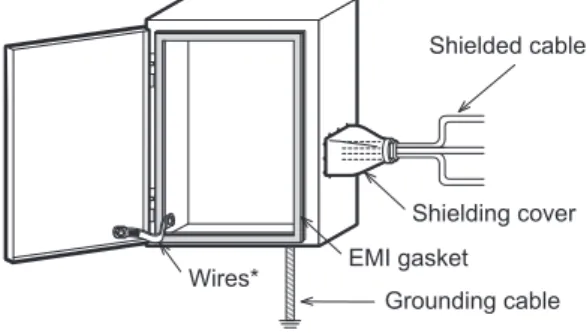
(c) To ensure that there is electrical contact between the control cabinet and its door, connect the cabinet and its doors with thick wires. (See Fig. 1.)
(d) In order to suppress the leakage of radio waves, the control cabinet must be structured with minimal openings. The gap between the control cabinet and its door must be eliminated whenever possible by attaching EMI gaskets between them. To attach an EMI gasket, remove the coating on the contact area between the control cabinet and its door and attach the EMI gasket with conductive adhesive tape. In addition, wrap the cable holes with a shielding cover or other shielding devices. (See to Fig. 1.)
EMI gasket
Shielding cover
Grounding cable Wires*
Shielded cables
* These wires are used to improve the conductivity between the door and control cabinet.
Fig. 1. Control Cabinet Example
(e) In order to avoid the effects of static electricity, make sure to eliminate static electricity when there is a possibility of touching the PLC in the control cabinet during maintenance or servicing.
(2) Cables
TECHNICAL BULLETIN
[ 3/4
]
[Issue No.]
HIME-T-P-0174A
(3) Noise fi lter
Please attach a noise fi lter on the power line. (See to Fig. 2.)
Mitsubishi’s EMC tests were carried out using SOSHIN ELECTRIC HF3010C-SZA.
(a) Separate and lay the input (power source side) and output (device side) cable away from the noise fi lter.
Do not bundle the input cable together and do not lay it close to the output cable. If input and output cables are installed together, interference may result due to noise being induced to the input cable from the output cable.
Bad
Good
Noise filter Noise
filter Noise Noise
Input cable (Power source side) Input cable
(Power source side)
Output cable (Device side) Output cable
(Device side)
Induction
Cabinet Cabinet
Installing the input and output cables together will cause noise induction.
Separate the input cable from the output cable.
Ferrite core Ferrite core
Fig. 2. Precautions on noise fi lter
(b) Grounding wires of the noise fi lter should be as short as possible.
(4) Ferrite core
Always attach a ferrite core to cables that extend outside the control panel, including power cable. Mitsubishi performed the EMC test with 1 turn around SEIWA ELECTRIC E04SR401938.
(5) Power supply
TECHNICAL BULLETIN
[ 4/4
]
[Issue No.]
HIME-T-P-0174A
REVISIONS
Version Date Revision A November 2016 First edition