13th IEEE International Symposium on Design and Diagnostics of Electronic Circuits and Systems (DDECS 2010), pp. 193-196, April 2010.
SREEP: Shift Register Equivalents Enumeration and
Synthesis Program for Secure Scan Design
Katsuya Fujiwara
1, Hideo Fujiwara
2, Marie Engelene J. Obien
2and Hideo Tamamoto
11 Faculty of Engineering and Resource Science Akita University
Akita, 010-8502, JAPAN {fujiwara, tamamoto}@ie.akita-u.ac.jp
2 Graduate School of Information Science Nara Institute of Science and Technology
Nara 630-0192, JAPAN {fujiwara, obien-j}@is.naist.jp
Abstract—We reported a secure scan design approach using extended shift registers that are functionally equivalent but not structurally equivalent to shift registers. The security level of the secure scan architecture based on those shift register equivalents is determined by the probability that an attacker can identify the configuration of the shift register equivalent used in the circuit, and hence the attack probability approximates to the reciprocal of the cardinality of the class of shift register equivalents. In this paper, we clarify the cardinality of each class of shift register equivalents from several linear structured circuits and the cardinality of the whole class of shift register equivalents. We also consider the enumeration problem of shift register equivalents and the synthesis problem of desired shift register equivalents. A program called SREEP (Shift Register Equivalents Enumeration and Synthesis Program) is presented to solve those problems.
Keywords - scan design; shift register equivalents; security; testability; cardinality; enumeration.
I. INTRODUCTION
Both testability and security of a chip have become primordial to ensure its reliability and protection from invasion to access important information. However, both may have conflicting requirements for designers. To guarantee quality, designers use design for testability (DFT) methods to make digital circuits easily testable for faults. Scan design is a powerful DFT technique that warrants high controllability and observability over a chip and yields high fault coverage [2]. However, this also accommodates reverse engineering, which contradicts security. For secure chip designers, there is a demand to protect secret data from side-channel attacks and other hacking schemes [3]. Nevertheless, with improved control and access to the chip through DFT, the chip becomes more vulnerable to attacks. Scan chains can be used to steal important information such as intellectual property (IP) and secret keys of cryptographic chips [4-6]. Despite all these, security chips can be made more susceptible to errors, and thus, not secure, if they are faulty. Therefore, testability is as important as security for secure IC designers to guarantee the quality of security and functionality of the chip. Hence, there is a need for an efficient solution to satisfy both testability and security of digital circuits. To solve this challenging problem, different approaches have been proposed [3-11]. All the
approaches except [8,11] add extra hardware outside of the registers.
In [11], we reported a secure and testable scan design approach by using extended shift registers that are functionally equivalent but not structurally equivalent to shift registers. This approach is only to replace the original scan registers with the modified extended scan register, and hence requires little area overhead and no performance overhead with respect to normal operation. The security level of the secure scan architecture based on those shift register equivalents is determined by the probability that an attacker can identify the configuration of the shift register equivalent used in the circuit, and hence the attack probability approximates to the reciprocal of the cardinality of the class of shift register equivalents. In this paper, we clarify the cardinality of each class of shift register equivalents from several linear structured circuits and the cardinality of the whole class of shift register equivalents. We also consider the enumeration problem of shift register equivalents and the synthesis problem of desired shift register equivalent. A program called SREEP (Shift Register Equivalents Enumeration and Synthesis Program) is presented to solve those problems.
II. SHIFT REGISTER EQUIVALENTS
Definition 1: A circuit whose state transition graph is isomorphic to that of a k-stage shift register is called a k-stage extended shift register.
Definition 2: A circuit C is called functionally equivalent to a k-stage shift register (or SR-equivalent) if the state transition graph of C is isomorphic to that of the shift register and the input/output assignment is the same as that of the shift register. The state assignment is not necessarily the same as that of the shift register. (see Fig. 1(b)).
In the next section, we consider the following seven types of linear circuits that can realize extended shift registers: inversion inserted shift registers (I2SR), linear feed-forward shift registers (LF2SR), linear feedback shift registers (LFSR), linear feed-forward shift registers with inversion (LF2SR+I2SR), linear feedback shift registers with inversion (LFSR+I2SR), shift registers with linear feed-forward and feedback (LF2SR+LFSR), and shift registers with linear feed- forward, linear feedback and inversion (LF2SR+LFSR+I2SR) (see Fig. 2).
13th IEEE International Symposium on Design and Diagnostics of Electronic Circuits and Systems (DDECS 2010), pp. 193-196, April 2010.
(a) Shift register (b) SR-equivalent Figure 1. Shift register and SR-equivalent circuit
(a) I2SR (b) LF2SR
(c) LFSR (d) LF2SR+I2SR
(e) LFSR+I2SR (f) LF2SR+LFSR
(g) LF2SR+LFSR+I2SR Figure 2. Seven types of linear circuits
(a) Not output-equivalent (b) Modified Figure 3. Modification to SR-equivalent
III. CARDINALITY OF SR-EQUIVALENTS
A. I2SR
An inversion inserted shift register (I2SR) is obtained by inserting some inversions in a shift register.
Theorem 1: Any k-stage I2SR with even number of inversions is functionally equivalent to the k-stage shift register.
The total number of k-stage I2SRs is 2k+1-1. On the other hand, the total number of k-stage I2SRs that are SR-equivalent is 2k-1 from Theorem 1.
B. LF2SR and LFSR
Theorem 2: Any LF2SR can be modified to an LF2SR that is SR-equivalent to the k-stage shift register by manipulating the linear sum of the output.
Consider the circuit shown in Figure 3(a), the output assignment is different from that of the shift register only when state transition occurs from states (011), (010), (110), and (111), i.e., only when y2 is 1. Hence, as shown in Figure 3(b), by adding an XOR at the output with inputs from y3 and y2 that is indicated by the broken line arrow, the output assignment of the modified LF2SR becomes the same as that of the shift register of Figure 1(a). With this, only the state assignment is different while the input and output assignments remain the same, thus making it SR-equivalent.
Similarly, the following theorem for LFSR holds. Theorem 3: Any LFSR can be modified to an LFSR that is SR-equivalent to the k-stage shift register by manipulating the linear sum of the input.
Let us consider the cardinality of the classes of LF2SRs and LFSR together with their SR-equivalents. The total number of k-stage LF2SRs is 2k(k+1)/2-1. Similarly, the total number of k- stage LFSR is 2k(k+1)/2-1.
For each (k-1)-stage LF2SR, add one flip-flop to the right end and make it k-stage LF2SR. Since this k-stage LF2SR is not always SR-equivalent, modify it to be SR-equivalent by using Theorem 2. The number of such augmented k-stage SR- equivalent LF2SRs is equal to the total number of (k-1)-stage LF2SRs, and hence 2k(k-1)/2-1. Therefore, the total number of k- stage LF2SRs that are SR-equivalent is 2k(k-1)/2-1. Similarly the total number of LFSRs that are SR-equivalent is 2k(k-1)/2-1. Theorem 4: The cardinality of the class of k-stage LF2SRs (LFSRs) is 2k(k+1)/2-1. The cardinality of the class of k-stage LF2SRs (LFSRs) that are SR-equivalent is
2k(k-1)/2-1.
C. LF2SR+I2SR and LFSR+I2SR
Similar to Theorems 2 and 3, we have the following theorems.
Theorem 5: Any LF2SR+I2SR can be modified to an LF2SR+I2SR that is SR-equivalent to the k-stage shift register by manipulating the linear sum of the output and by adding inverters.
Theorem 6: Any LFSR+I2SR can be modified to an LFSR+I2SR that is SR-equivalent to the k-stage shift register by manipulating the linear sum of the input and by adding inverters.
Regarding the cardinality of the classes of k-stage LF2SR+I2SR, LFSR+I2SR and their SR-equivalents, we have the following theorem.
Theorem 7: The cardinality of the class of k-stage LF2SR+I2SRs (LFSR+I2SRs) is (2k(k+1)/2-1)(2k+1-1). The cardinality of the class of k-stage LF2SR+I2SRs (LFSR+I2SRs) that are SR-equivalent is (2k(k-1)/2-1)(2k-1). D. LF2SR+LFSR and LFSR+LFSR+I2SR
Theorem 8: The cardinality of the class of k-stage
LF2SR+LFSRs is (2k(k+1)/2-1)2. The cardinality of the class of k-stage LF2SR+LFSR+I2SRs is (2k(k+1)/2-1) 2 (2k+1-1).
13th IEEE International Symposium on Design and Diagnostics of Electronic Circuits and Systems (DDECS 2010), pp. 193-196, April 2010. E. Cardinality of Whole SR-equivalents
The cardinality of each class is summarized in Table I. The covering relation among seven classes is illustrated in Figure 4. Let N(k) be the number of all k-stage SR- equivalents. SR-equivalent circuits are the circuits whose state graphs are the same as that of SR except state assignment. The number of states is 2k and the number of state values is 2k, where k is the number of flip-flops. So, the total number of different SR-equivalent state graphs is the number of permutations to assign 2k values to 2k states, which is 2k!. Further, the size of each permutation (of state variables) equivalents is k!. Hence, the number of permutation equivalents is 2k!/k!. Therefore, we have
N(k) = 2k!/k! - 1.
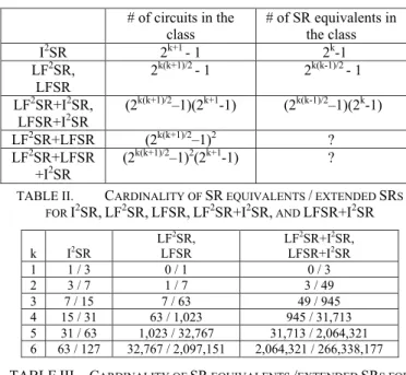
Table I shows the cardinality of each class and the cardinality of SR-equivalents in each class for k-stage circuits. Table II shows the computed values. From Table II, for each class (I2SR, LF2SR, LFSR, LF2SR+I2SR and LFSR+I2SR), we can observe that the cardinality of k-stage circuits in the class is equal to the cardinality of (k+1)-stage SR-equivalents in the class as shown in Theorems 4 and 7.
Figure 4. Covering relation among classes IV. SREEP
We made a program called SREEP (Shift Register Equivalents Enumeration and Synthesis Program) to solve the enumeration and synthesis problems for SR-equivalents [13]. SREEP adopts GUI (graphical user interface) for expressing outcome by circuit diagram and table. SR-ID code is introduced to represent the structure of each extended SR uniquely. Fig. 5 shows an example of outcome by SREEP.
V. ENUMERATION
PROBLEM FOR SR- EQUIVALENTS
For each class (I2SR, LF2SR, LFSR, LF2SR+I2SR, LFSR+I2SR, LF2SR+LFSR, and LF2SR+LFSR+ I2SR), we enumerated all k-stage extended SRs and identified SR- equivalents for k=1, 2, … and 6, in order to obtain the real number of SR-equivalents for each class.
For five classes of I2SR, LF2SR, LFSR, LF2SR+I2SR, and LFSR+I2SR, the real number of SR-equivalents for
k=1, 2, … and 6 obtained by SREEP is the same as the cardinality of SR-equivalents shown in Table II.
For other two classes of LF2SR+LFSR and LF2SR+LFSR+ I2SR, Table III shows the real number of SR-equivalents and the total number of extended SRs for k=1, 2, … and 6 obtained by SREEP.
SREEP can generate all SR-equivalents that satisfy the given desired parameters or constraints such as type of circuit
TABLE II. CARDINALITY OF SR EQUIVALENTS / EXTENDED SRS FOR I2SR,LF2SR,LFSR,LF2SR+I2SR, AND LFSR+I2SR k I2SR
LF2SR, LFSR
LF2SR+I2SR, LFSR+I2SR
1 1 / 3 0 / 1 0 / 3
2 3 / 7 1 / 7 3 / 49
3 7 / 15 7 / 63 49 / 945
4 15 / 31 63 / 1,023 945 / 31,713
5 31 / 63 1,023 / 32,767 31,713 / 2,064,321 6 63 / 127 32,767 / 2,097,151 2,064,321 / 266,338,177
TABLE I. CARDINALITY OF EACH CLASS
# of circuits in the class
# of SR equivalents in the class
I2SR 2k+1 - 1 2k-1
LF2SR, LFSR
2k(k+1)/2 - 1 2k(k-1)/2 - 1 LF2SR+I2SR,
LFSR+I2SR
(2k(k+1)/2–1)(2k+1-1) (2k(k-1)/2–1)(2k-1)
LF2SR+LFSR (2k(k+1)/2–1)2 ?
LF2SR+LFSR +I2SR
(2k(k+1)/2–1)2(2k+1-1) ?
Figure 5. Outcome example by SREEP
TABLEIII. CARDINALITY OF SR EQUIVALENTS /EXTENDED SRS FOR
LF2SR+LFSR AND LF2SR+LFSR+I2SR BY SREEP
k LF2SR+LFSR LF2SR+LFSR+I2SR
1 0 / 1 0 / 3
2 0 / 49 0 / 343
3 12 / 3,969 84 / 59,535
4 905 / 1,046,529 13,575 / 32,442,399 5 198,505 / 1,073,676,289 6,153,655 / 67,641,606,207 6 180,038,401 /
4,398,042,316,801
11,342,419,263 / 558,551,374,233,727
13th IEEE International Symposium on Design and Diagnostics of Electronic Circuits and Systems (DDECS 2010), pp. 193-196, April 2010. structure, number of stages, upper and lower limits of the
number of feed-forwards/feedbacks, etc.
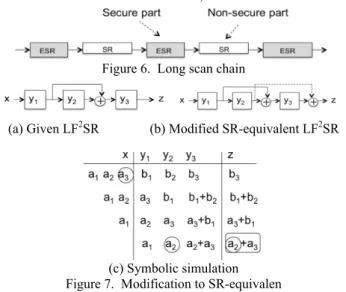
Figure 6. Long scan chain
(a) Given LF2SR (b) Modified SR-equivalent LF2SR
(c) Symbolic simulation Figure 7. Modification to SR-equivalen VI. SYNTHESIS PROBLEM FOR SR-EQUIVALENTS
One of the important problems for secure scan design is how to synthesize SR-equivalents that satisfy desired properties and constraints. For a long scan chain, we can design a long SR-equivalent by concatenating short SR- equivalents. Further, we can reduce area overhead by using SR-equivalents (ESR, extended SR-equivalent to SR) only for secure parts, as shown in Fig. 6.
To generate scan sequences (state-justification and state- observation sequences) easily from the structure of a given SR-equivalent, the five classes of I2SR, LF2SR, LFSR, LF2SR+I2SR, and LFSR+I2SR are more desirable than the classes of LF2SR+LFSR and LF2SR+LFSR+I2SR. To reduce power consumption during scan shift operation, an approach to inserting inverters and feed-forward type XOR gates into a scan chain has been proposed in [12]. Therefore, we can consider the following approach. First, we insert NOT and XOR gates into a scan chain to minimize power consumption during scan operation by using the method of [12]. Next, we check if the augmented scan register or extended SR is functionally equivalent to SR or not. If not, we augment it to SR-equivalent with minimal modification.
Let us consider the problem of modifying a given extended SR into SR-equivalent. Consider a k-stage LF2SR given in Fig. 7(a). Here, k=3. By symbolic simulation illustrated in Fig. 7(c), the output z at time k+1=4 becomes a2+a3. To change a2+a3 into a3, we add another value a2 to the output z, i.e., a2+a3+a2= a3. To do so, we modify the circuit by adding another feed-forward from y2 to z as shown in Fig. 7(b). Then the modified circuit becomes SR-equivalent. In this way, for a k-stage LF2SR, the additional feed-forward line is uniquely determined from the output expression at time k+1 obtained by symbolic simulation.
In case of LFSR, such an additional value can be added to the input x of the LFSR by adding an extra feedback from the flip-flop of the value to the input x. There are cases of adding more than one feed-forward or feedback to make it SR- equivalent, but those are determined uniquely.
For LF2SR+I2SR or LFSR+I2SR, not only feed-forwards or feedbacks are added but also a NOT gate to z or x, if necessary.
VII. CONCLUSIONS
The security level for the secure scan design based on SR- equivalents is related to the attack probability which approximates to the reciprocal of the cardinality of the class of SR-equivalents. In this paper, we clarified the cardinality of each class of SR-equivalents from several linear structured circuits and the cardinality of the whole class of SR- equivalents, and presented the real number of SR-equivalents by enumeration for up to 6-stage SR-equivalents. We also considered the enumeration problem of SR-equivalents and the synthesis problem of desired SR-equivalents. A program called SREEP (Shift Register Equivalents Enumeration and Synthesis Program) was presented to solve those problems.
REFERENCES
[1] S. W. Golomb, Shift Register Sequences, Aegean Park Press 1982. [2] H. Fujiwara, Logic Testing and Design for Testability, The MIT Press
1985.
[3] B. Yang, K. Wu, and R. Karri. "Scan based side channel attack on dedicated hardware implementations of data encryption standard." International Test Conference 2004, pp. 339–344, 2004.
[4] B. Yang, K. Wu, and R. Karri. "Secure scan: A design-for-test architecture for crypto chips." IEEE Trans. on Computer-Aided Design of Integrated Circuits and Systems, Vol. 25, No.10, pp. 2287–2293, Oct. 2006.
[5] D. Hely, M. L. Flottes, F. Bancel, B. Rouzeyre, and N. Berard. “Scan design and secure chip,” 10th IEEE International On-Line Testing Symposium, pp. 219–224, 2004.
[6] J. Lee, M. Tehranipoor, C. Patel, and J. Plusquellic. “Securing designs against scan-based side-channel attacks.” IEEE Trans. on Dependable and Secure Computing, Vol. 4, No. 4, pp. 325–336, Oct.-Dec. 2007. [7] S. Paul, R. S. Chakraborty, and S. Bhunia. “VIm-Scan: A low overhead
scan design approach for protection of secret key inscan-based secure chips.” 25th IEEE VLSI Test Symposium, pp. 455–460, 2007. [8] G. Sengar, D. Mukhopadhyay, and D. R. Chowdhury. “Secured flipped
scan-chain model for crypto-architecture.” IEEE Trans. on Computer- Aided Design of Integrated Circuits and Systems, Vo. 26, No.11, pp. 2080-2084, November 2007.
[9] M. Inoue, T. Yoneda, M. Hasegawa, and H. Fujiwara, “Partial scan approach for secret information protection,” 14th IEEE European Test Symposium, pp.143 -148, May 2009.
[10] U. Chandran and D. Zhao, “SS-KTC: A high-testability low-overhead scan architecture with mult-level security integration,” 27th IEEE VLSI Test Symposium, pp. 321-326, May 2009.
[11] H. Fujiwara and M. E. J. Obien, “Secure and testable scan design using extended de Bruijn graph,” 15th Asia and South Pacific Design Automation Conference, pp.413-418, Jan. 2010.
[12] O. Sinanoglu and A. Orailoglu, “Modeling scan chain modifications for scan-in test power minimization,” International Test Conference 2003, pp. 602-611, 2003.
[13] K. Fujiwara and H. Fujiwara, SREEP: http://sreep.fujiwaralab.net/