Instruction-Based Self-Test for Sequential Modules in Processors
Michiko Inoue Kazuko Kambe Naotaka Hoashi
Hideo Fujiwara
Graduate School of Information Science
Nara Institute of Science and Technology
Abstract
Instruction-based self test of processors attracts atten- tion as a testing strategy achieving at-speed testing without performance penalty or area overhead. This pa- per introduces input temporal spatial constrains of se- quential modules for instruction-based self test of pro- cessors. The proposed constraints are used to gen- erate test sequences for sequential modules, and the obtained test sequences are later transformed into test programs for the modules in instruction-based self test fashion. This paper proposes methods for test program generation and redundancy identification for sequential modules. Experimental results show that the proposed method obtains high fault efficiency.
1 Introduction
Today’s processors with high performance and rich functionality absolutely require accurate and at-speed testing. Though scan design enables systematic test- ing with high test quality and short turn-around time, it induces performance penalty and area overhead due to scan chains, and moreover, it is difficult to achieve at-speed testing. Hardware BIST realizes at-speed test- ing. However, it requires high area overhead and may involve manual efforts to make a circuit BIST- ready. Moreover, test application using nonfunctional and high-switching random patterns consumes more power than normal operation.
Software-based self test of processors attracts atten- tion as a testing strategy achieving at-speed testing. In this strategy, a processor enables self-test by running
This work is supported in part by Semiconductor Technology Academic Research Center (STARC) and Japan Society for the Pro- motion of Science (JSPS) under the Grant-in-Aid for Science Re- search No.15300018.
Currently, Sony LSI Design Inc.
a sequence of instructions called a test program. It does not induce any performance penalty, area over- head or excessive power. A number of approaches [1, 2, 3, 4, 5, 6, 7, 8, 9] are proposed for software-based self testing.
Recent works link tests for modules inside proces- sors with test programs to achieve high fault efficiency for structural fault models. Krantis et al.[5] propose ef- ficient deterministic approach for modules with regu- lar structures. The methods [6, 7, 8, 9] use structural ATPG to generate tests for modules inside processors to get high test quality. In software-base self test, we apply tests for a processor using a test program(a se- quence of instructions of the processor), therefore, val- ues or sequences of values applicable to modules inside the processor are restricted. These works extract such restriction for modules as constraints, then apply ATPG to modules with the extracted constraints. Finally, the generated tests are transformed into test programs. The method proposed in [6] targets path delay faults. The proposed method examines all the pairs of instructions and extract constraints induced by them while identi- fying redundant faults. Singh et al.[7] propose an ap- proach that efficiently identify some untestable path de- lay faults only using high-level information of proces- sors.
The methods in [8] and [9] consider test program generation based on test program templates (or just tem- plates, hereafter) for stuck-at faults. A template is an instruction sequence with unspecified operands that de- livers tests to a module under test and observes the test responses. The methods have an advantage that con- straints can be extracted accurately from each template since the template represent ways to propagate tests from primary inputs and the the test response to primary outputs. Therefore, the generated tests for a module are guaranteed to be transformed into test programs. Chen et al.[8] propose a scalable methodology. However, the
IEEE 5th Workshop on RTL and High Level Testing (WRTLT'04), pp. 109-114, Nov. 2004.
method is required to generate a set of all the possi- bly useful templates in advance, and moreover, the pro- posed template generation method considers only in- put spaces of a module determined by operands of one or two instructions which directly affect the module. We[9] are also proposing a template based test program generation method. In the proposed method, we effi- ciently generate multiple templates so that the first tem- plate covers large input space and the succeeding tem- plates cover different input spaces. The method care- fully considers the input space of a module determined by not only operands of instructions but also registers whose values depend on a series of instructions.
The methods targeting stuck-at faults[5, 8, 9] work effectively for combinational modules, since they con- sider test patterns for modules. However, none of them consider sequential modules explicitly. There exists an approach [10] targeting a specific sequential module. However, it is difficult to extend the ideas for general sequential modules.
In this paper, we propose a test program generation method for sequential modules. We introduce a input temporal spatial constraintfor sequential modules, and then propose test program generation method based on templates. We also consider how to identify redundant faults. Experiment results shows the proposed method obtains high fault efficiency.
The rest of the paper is organized as follows. We briefly explain our template based test program genera- tion method in Section 2. Section 3 introduces a input temporal spatial constraint, and a test program genera- tion method is proposed in Section 4. The experimental results are shown in Section 5, and Section 6 concludes this paper.
2 Template based test program
generation
We are proposing template based test program genera- tion for processors, where we combine test generation for modules and transformation the obtained tests into test program[9]. In software-base self test, we apply tests for a processor using a test program, therefore, val- ues or sequences of values applicable to modules inside the processor are restricted. To generate tests which is guaranteed to be transformed into a sequence of instruc- tion, test generation for a module with constraints is considered, where constraints represents values or se-
LDA loc1 ADD loc2 AND loc3
Figure 1: Test program template.
quences of values which can be applied to a module inside a processor using instructions.
In our method, constraints are extracted by templates. A template is a sequence of instructions with unspeci- fied operands. It consists of instructions which propa- gate tests to a target module from primary inputs and the test response from outputs of the module to primary out- puts. Figure1 shows an example of a template, where , and are operands of instructions but their values are unspecified. For a given processor, it is diffi- cult to obtain an accurate constraint for each module, while we can extract an accurate constraint for each template. However, each template might cover a sub- set of possible input space of the module. In [9], we are proposing efficient template generation method where we generate multiple templates to cover input space for modules. We consider an input space of a module de- termined by not only operands of an instruction but also values of registers whose values depend on a series of instructions such as status registers. The method works efficiently for combinational modules since they require test patterns rather than test sequences.
3 Input temporal spatial con-
straint
In our template based test program generation method, we apply ATPG with constraints to modules inside pro- cessors. Since a sequential module requires a test se- quence to be tested, we should consider a sequence of constraints on the input space. We call it an input tem- poral spatial constraint.
We consider input temporal spatial constraints using a controller of Parwan processor[11] as an example. Parwan processor is an accumulator based 8-bit pro- cessor with 17 instructions(Fig.2). The controller has four inputs (Instruction Register), (Status Regis-
ter), , where and are registers
and and are primary inputs. Two reg- isters and have load control signals as inputs from the controller. The register consists of four
Controller ALU
SHU
AC SR IR
interrupt ready
PC
MAR
#$75 OGOQT[ #&$75
Figure 2: Parwan processor.
flags , , , that represent overflow, carry, zero, sign, respectively. Parwan processor takes multiple cy- cles to execute one instruction.
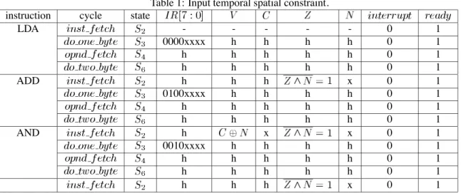
Table1 shows a relation between input spaces and a sequence of instructions shown in Fig.1. An execution of each instruction consists of multiple cycles, and a state and values of inputs of a controller at each cycle are shown. During the execution, we fix and to , respectively. Symbols ’-’ and ’h’ means an unknown value and the same value as the previous cycle, respectively, and ’x’ means any value can be as- signed. From the table, we can find that inputs are up- dated at some specific cycles (temporal constraints) as well as their values are restricted (spatial constraints). An input temporal spatial constraint of a module is a sequence of input constraints, where an input constraint represent a set of values of inputs of the module that are constrained by values at the present and the last cycle. In Table1, each row corresponds to a input constraint, and any continuous cycles correspond to a input tempo- ral spatial constraint.
4 Test program generation
4.1 Outline
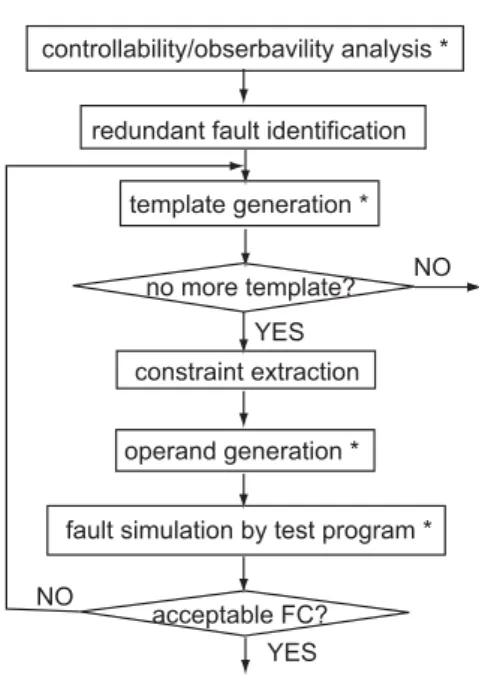
Now we propose a test program generation method for sequential modules. Figure3 shows an outline of a pro- posed method. We adopt template based test program generation like combinational modules. In the proposed method, we first analyze controllability and observabil- ity of registers, and identify some redundant faults. The
controllability/obserbavility analysis *
redundant fault identification
template generation *
constraint extraction
operand generation *
fault simulation by test program * no more template?
acceptable FC?
NO
YES YES
NO
Figure 3: Outline of the method.
results of these pre-processes are used when selecting instructions for templates or setting a target fault cov- erage at later steps. Then we repeatedly generate tem- plates as follows. We first generate a template of a test program for a sequential module under test, and extract an input temporal spatial constraint from the template. We apply sequential ATPG to the module with the ex- tracted constraint and obtain test sequence. Finally, we obtain values of operands from the test sequence. We repeat this process until achieving acceptable fault cov- erage or trying all the generated templates.
In Fig.3, steps marked with ’*’ are proposed in [9], and therefore, we mainly explain other steps in this pa- per.
4.2 Template generation
Since there is no limitation for the length of an in- put temporal spatial constraint, it is impossible to ex- tract all the constraints. Instead, we generate templates so that they can cover possible input space of a tar- get module at some cycle, and then extract constraints from each template. We can use a template generation method for combinational modules([9]) in this purpose. This method efficiently generate multiple templates that cover large input space for combinational modules.
The method generates each template so that it cov-
Table 1: Input temporal spatial constraint. instruction cycle state
LDA - - - 0 1
0000xxxx h h h h 0 1
h h h h h 0 1
h h h h h 0 1
ADD h h h x 0 1
0100xxxx h h h h 0 1
h h h h h 0 1
h h h h h 0 1
AND h x x 0 1
0010xxxx h h h h 0 1
h h h h h 0 1
h h h h h 0 1
h h h x 0 1
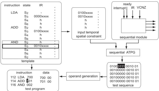
ers some input space for a target module at some cy- cle. We call the cycle a maximal input space cycle of the template. In a method proposed in this paper, we extract an input temporal spatial constraint correspond- ing to cycles that depend on one instruction including the maximal input space cycle of a template. That is because the timing when inputs are updated mainly de- pend on one instruction. Figure4 illustrates how to ex- tract a constraint and how to generate a test program. We consider that the first some cycles till instruction fetch cycle depend on the last instruction as well as the current instruction. Therefore, we extract an constraint from the first cycle of the instruction to the instruction fetch cycle of the next instruction.
Figure 4 illustrates an example of test program gen- eration. Consider a template in Fig.1, and assume that a maximal input space cycle of the template is the second cycle of AND instruction (see Table1). At the cycle, we can justify any value satis-
fying ”0010xxxx”, , ,
and . We extract an input temporal spatial constraint for cycles from
of AND to of the next instruction, since AND includes the maximal input space cycle. We ap- ply sequential ATPG to the controller with the extracted input temporal spatial constraint, then obtain a test se- quence. We generate values of operands appeared in the template from the test sequence and obtain test pro- gram. For example, the lowest 4 bits of correspond to the highest 4 bits of , and of memory addresses1. The lowest 4 bit ”0111” of in the first
1LDA, ADD and AND are 2 byte instruction, and the second byte
vector of a test sequence is transformed ’7’ of the high- est 4 bit of of ADD in a test program (’7’ is in hexadecimal notation).
4.3 Redundant fault identification
We identify redundant faults prior to test program gen- eration. Here, we consider a fault is redundant if no test program detects the faults. In the proposed test pro- gram generation method, we could not identify redun- dant faults since we could not enumerate all the possible templates. However, redundant faults can be identified if we use constraint relaxed enough to cover all the pos- sible input temporal spatial constraints.
To identify some of redundant faults, we consider a circuit composed of a target module and registers at its inputs. We include control signals to the registers if the target module generates them, otherwise, we further in- clude a controller generating the control signals, regis- ters at inputs of the controller and control signals for in- put registers for the target module and the controller. In case of the controller of Parwan processor, we consider the circuit shown in Fig.5. This circuit implicitly repre- sent all the possible temporal constraints, and therefore, if a fault is identified redundant in this circuit, the fault is also redundant in the processor.
represents the lowest 8 bits of the address.
template
input temporal spatial constraint
sequential ATPG sequential module
test sequence operand generation
interrupt ready
IR VCNZ
112 LDA 700 114 ADD 701 116 AND 002
instruction state IR
LDA S2 - S3 0000xxxx S4 h S6 h ADD S2 h S3 0100xxxx S4 h S6 h AND S2 h S3 0010xxxx S4 h
S6 h S2 h
0100xxxx 0010xxxx h h h
test program
01000111 0010 01 00100000 0010 01 00100000 0010 01 00100000 0010 01 00100000 0010 01 instruction data
700 00 701 00
Figure 4: Test program generation.
Controller
SR IR
interrupt ready
Figure 5: Circuit for redundancy identification.
5 Experiment results
We evaluated the proposed method for a controller of Parwan processor. The experiments used a logic syn- thesis tool Design Compiler (Synopsys), test generation tool TestGen (Synopsys). To apply fault simulation for a whole processor, we extract values at primary inputs (DATABUS from memory) of the processor during ex- ecuting the generated test program using RTL VHDL simulator Scirocco (Synopsys). We consider a fault is
detected if some error is propagated at primary output (ADBUS or DATABUS). In the current version, we as- sume that a fault in a controller is detectable if an error is propagated at the outside of the controller. We ob- tained fault coverage under this assumption.
Table2 shows results of the proposed method. We generated 299 templates using the method proposed in [9]. We extracted input temporal spatial constraints from the templates, and then applied sequential ATPG if the same constraint has not been extracted so far. As a result, we applied ATPG with 46 constraints. Among these constraints, 19 constraints actually contributed to get the reported fault coverage. The generated test se- quence detected 600 faults for the controller, and the transformed test program also detected 600 faults. On the other hand, we identified 29 redundant faults. Con- sequently, we can achieve fault efficiency of 93.88%. The number of cycles required to execute the test pro- gram is 398.
In the test program generation, we fixed the value of to 1 because makes the transition to the next state wait (the controller keeps the same state while ) and we do not handle such behavior in the current version. We examined the number of redundant faults when the value of is fixed to , and found
Table 2: Results on Parwan controller
total faults 670
identified redundant faults 29 (4.33%)
generated templates 299
sequential ATPG trial 46
faults detected by sequential ATPG 600 (89.55%) faults detected by fault simulation 600 (89.55%)
fault efficiency 93.88%
test application time (cycles) 398
66 redundant faults. That is, the generated test program can detect 600 faults among 604 faults that may be de- tectable under the condition of .
In a few literatures on software-based self test of processors, fault coverage of Parwan controller are re- ported. L. Chen et al. [8] reports 88.26% and N. Krani- tis et al.[5] reports 87.68%. Their methods do not treat a controller directly, and the fault coverage is obtained by fault simulation of test programs generated for other combinational modules. In addition, they don’t con- sider redundancy identification. On the other hand, our method directly treat a controller and can achieve high fault efficiency. Here, we should note that we as- sume a fault to be detectable if an error is propagated at the outside of a controller. To justify the assumption, we should generate additional instructions to propagate such errors to primary outputs. This is our on-going work, and therefore, we could not give completely fair comparison with related works in the current version.
6 Conclusions
In this paper, we proposed a method for instruction- based self test for sequential modules inside processors. We introduced an input temporal spatial constraint for sequential modules, and proposed a test program gen- eration method using the constraints and redundancy identification method. We demonstrated the effective- ness of the proposed method using a controller of Par- wan processor as an example. The proposed method achieved high fault efficiency. We already proposed effective test program generation method for combina- tional modules. Therefore, we can effectively generate test programs for both combinational and sequential cir- cuits.
References
[1] D. Brahme and J. A. Abraham, “Functional testing of microprocessors,” IEEE Trans. on Computers, vol. 33, pp. 475–485, June 1984.
[2] K. Batcher and C. Papachristou, “Instruction ran- domization self test for processor cores,” in Proc. 17th VLSI Test Symposium, pp. 34–40, 1999. [3] J. Shen and J. Abraham, “Native mode functional
test generation for processors with applications to self-test and design validation,” in Proc. Interna- tional Test Conference 1998, pp. 990–999, 1998. [4] F. Corno, C. Cumani, M. S. Reorda, and
G. Squillero, “Fully automatic test program gen- eration for microproessor cores,” in Proc. Design, Automation & Test in Europe, 2003, pp. 1006– 1011, 2003.
[5] N. Krantis, A. Paschalis, D. Gizopoulos, and Y. Zorian, “Instruction-based self-testing of pro- cessor cores,” Journal of Electronic Testing: The- ory and Application, vol. 19, pp. 103–112, 2003. [6] W.-C. Lai, A. Krstic, and K.-T. Cheng, “Test pro-
gram synthesis for path delay faults in micropro- cessor cores,” in Proc. International Test Confer- ence 2000, pp. 1080–1089, 2000.
[7] V. Singh, M. Inoue, K. Saluja, and H. Fujiwara,
“Instruction-based delay fault testing of processor cores,” in Proc. International Conference on VLSI Design 2004, pp. 933–938, 2004.
[8] L. Chen, S. Ravi, A. Raghunath, and S. Dey, “A scalable software-based self-test methodology for programmable processors,” in Proc. 40th Design Automation Conference, pp. 548–553, 2003. [9] K. Kambe, M. Inoue, and H. Fujiwara, “Efficient
template generation for instruction-based selt-test of processor cores,” in Proc. 13th Asian Test Sym- posium, 2004.
[10] A. Almukhaizim, P. Petrov, and A. Orailoglu,
“Faults in procesor control subsystems: Testing correctness and performance faults in the data prefetching unit,” in Proc. 10th Asian Test Sym- posium, pp. 319–324, 2001.
[11] Z. Navabi, VHDL Analisis and Modeling of Digi- tal Systems. McGraw-Hill, 1997.