ESP1104 Summary Notes (1) © Lim Fang Jeng
1
Lecture 2:
Capacitors, Inductors & Transient Analysis
Capacitor
Capacitor is a voltage device, the current is the result.
Formed by two metal plates separated by an insulator in between - Driven by electrostatic repulsion
- Voltage across the plate will gradually increase until it arrive to the point where it is the same as the supply voltage, then the capacitor is said to be fully charged.
- ∆ = � × ∆� - � = ��
o � = �� = 8.854 × 10⁻¹²� = 1
36� × 10
−9� (dielectric constant in air) o � = cross section of plates; d=distance between plates
o Relative permittivity, � = ���
- Breakdown voltage – Voltage at which the insulating property of capacitor lost
- Dielectric plate should be made as thin as possible to increase capacitance = lower breakdown voltage
Current in capacitor
� = =� �
The smaller the capacitance, faster it get charged up. Capacitive circuits
In series:
� = � + � + ⋯+ ��
In parallel:
� =� + � + ⋯ + �� Energy stored in capacitors
Power is defined as
� = × � = � If the capacitor is initially uncharged, i.e. t=0, v=0,
= � = � = � = � ( )
Practical Capacitor
Capacitors in practical has internal inductance, resistances, usually these are not so significant because the resistance in wires are normally larger than the effects.
ESP1104 Summary Notes (1) © Lim Fang Jeng
2 Inductors
Inductor is essentially a current driven device (create magnetic field) v t = Ldi
dt L= Inductance (Henry (H)) – commonly in mH range Energy stored in Inductors, w(t),
p t = i(t) × v(t) = i t Ldi dt w t = L di
dtdt
t 0
= L di
i 0
=1 2Li
2(t)
Inductive Circuits
In series In parallel
= + +⋯ + = � + � + ⋯+ ��
Practical Inductors
Very often, the capacitance �� and the parallel resistor � is not significant. Hence, we often draw a practical inductor as
This is the resistance of the connecting wires
Position Sensor (Analysis of displacement and voltage)
Let the voltages at A and B be
� = � (� )
� = � (� ) where and are dependent on the position of the ferrite core - If = , ferrite core at the middle, � = � − � =
- If ≠ , ferrite core is shifted, � = � − � = − � � = ��
C is a constant proportional to the displacement distance x with amplitude of output voltage. Transformers
For ideal transformers
�
� =
�
� and
�
� =
�
� � = � ( )
ESP1104 Summary Notes (1) © Lim Fang Jeng
3
Transient Analysis
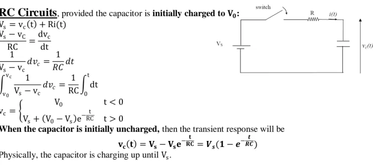
RC Circuits
, provided the capacitor is initially charged to � : Vs = vc t + Ri(t)Vs − vC
RC =
dvc 1 dt
Vs − vc � = 1
� 1
Vs − vc �
vc v0
= 1 RC dt
t
0
vc =
V0 t < 0 Vs + V0− Vs e−RCt t > 0�
When the capacitor is initially uncharged, then the transient response will be
� = � − � − � = � ( − −��) Physically, the capacitor is charging up until Vs.
The advantage of knowing the transients of the RC circuit is that we can minimize distortions of signals by manipulating the time constant, � = �
During charging, we will want to have the result such that the time constant τ T, then the result will be the least distorted. This can be useful in digital circuits.
During discharging, for the voltage across the resistor VR, we prefer τ T in order to decouple DC variations
Figure 1 Charging of Capacitor Figure 2 Voltage discharge across Resistor
Rise Time = Time interval over the wavefrom when it rises from 10% to 90%. Fall Time = Time interval over the wavefrom when it falls from 90% to 10%.
Vc
Vs = 1− e
−RCt
At 10%, 0.1 = 1− e−RCt 1 ; At 90%, 0.9 = 1− e−RCt 2
∴ � = − ≈ . �
Hence, capacitor can be used to decouple DC variations in a circuit which sometimes we do not desire. Whenever a much more complicated circuit is encountered, finding Thevenin’s Voltage and
Resistance first and then carry on the transient analysis.
ESP1104 Summary Notes (1) © Lim Fang Jeng
4
RL Circuits
Provided the inductor has a current i0 vL = Ldi
dt Vs = vL+ iR
= Ldi dt+ iR 1
Vs − iRdi = 1 Ldt
� = �
< 0
� + � −� − > 0�
If the inductor is initially no induced current, then the transient response will be
� =� − − To investigate the voltage across the inductor, utilize v = Ldi
dt,
Ldi dt=
LVs
R 0 + R L e
−RtL
� = � − The time constant is � =
If the inductor circuit is initially connected when t<0 and opened when t>0, then i 0 =Vs
R and i ∞ = 0
i t = 0 + VRs − 0 e−RtL = � e−RtL
When dealing with complicated circuits, always remember to convert the circuit to an equivalent circuit.
During the process, switching of circuits may occur, so one must take note of the change of effective resistance, time constant and the initial and final induced current.
Understanding the transient response of inductor can help in analyzing the motors.
When motors are switched off, a very large negative voltage occurs, which causes sparks. For the example below, we can see that the voltage across the inductor is
vm =−694.4e−6.93t
RLC Time Response
In RLC circuit, second order circuits occurs and there are
Over-damped case
Critically damped case and
Under-damped case
So we should make adjusting to avoid underdamping occurs in circuits.