EXPERIMENTAL STUDY OF TURBULENCE PROPERTIES
FOR A BOUNDED JET FLOW
著者
NOZAKI Tsutomu, NAKASHIMA Masahiro
journal or
publication title
鹿児島大学工学部研究報告
volume
32
page range
9-20
別言語のタイトル
拘束噴流の乱流特性
URL
http://hdl.handle.net/10232/12428
EXPERIMENTAL STUDY OF TURBULENCE PROPERTIES
FOR A BOUNDED JET FLOW
著者
NOZAKI Tsutomu, NAKASHIMA Masahiro
journal or
publication title
鹿児島大学工学部研究報告
volume
32
page range
9-20
別言語のタイトル
拘束噴流の乱流特性
URL
http://hdl.handle.net/10232/00002232
EXPERIMENTAL STUDY OF TURBULENCE PROPERTIES
FOR A BOUNDED JET FLOW
Tsutomu NOZAKI and Masahiro NAKASHIMA*
Abstract
Turbulence properties of a bounded jet flow, such as the turbulence intensity in streamwise, trans
verse and spanwise directions, the turbulence energy, the Reynolds stress and the production term of
turbulence energy, are measured in the mid—plane of a bounded jet flow and in the planes parallel to
this plane, by using the rectangular nozzle whose aspect ratio is 2. The variations of these turbulence
properties both in transverse direction and in spanwise direction are discussed, as compared to those in the initial mixing region of a two—dimensional jet flow. It has been found that the turbulence in tensity in the transverse direction is independent of the existence of the bounding plates and that the variations of the streamwise turbulence intensity correspond to those of the production term of turbu lence energy. Furthermore, at a certain downstream location from the nozzle exit, the mean flow and turbulence properties in the cross section normal to streamwise direction are also investigated. The secondary flow and the streamwise vorticity have been obtained by measuring the mean velocity com ponents in transverse and spanwise directions. The contour lines of the turbulence intensity, the Reynolds stress and the vorticity have been obtained. Turbulence properties of a bounded jet flow are clarified by using these results.
INTRODUCTION
A jet flow issuing from the nozzle into the space bounded by two parallel flat plates is called a bound ed jet flow. In this flow, the mean velocity in the vicinity of the bounding plates is larger than that in the middle part of the flow. This flow can be regarded as a complex turbulent flow, which is the result of interactions of free turbulence as a jet flow in the region far from the bounding plates and wall turbulence as a boundary layer flow in the region near the bounding plates. Therefore, the bounded jet flow is not only important practically but also interesting from the point of view of fluid dynamics.
A bounded jet flow can be found in internal flows such as the wall—reattachment—type fluidic devices[l] or the narrow combustion unit[2]. Several investigations concerning the bounded jet flow have been done in order to improve the performance of these devices and units. The peculiarity[3] of the velocity distribution in transverse direction, the effects[4] of the nozzle aspect ratio on the flow field, the effects[4—6] of the Reynolds number and the turbulence intensity at the nozzle exit as dyna mic initial conditions, and the effects[6,7] of the nozzle shape as geometric condition have been in vestigated so far. In these works, however, only the time—averaged flow properties were discussed.
On the other hand, few investigations concerning the turbulence properties of the bounded jet have been carried out. Gray and Shearer[8] measured the turbulence intensity in streamwise direction. Nakashima et al.[9] investigated the streamwise variations of the turbulence intensity in
wise, transverse and spanwise directions, the integral length scale and the power spectrum. They[10] also studied the effects of the nozzle aspect ratio on these turbulence properties.
By using the k— e model, Nakayama and Ogino[ll] analyzed the flow in the wall—reattachment— type fluidic devices, assuming it to be a two—dimensional turbulent jet flow. In those devices, howev er, the flow is actually three—dimensional and turbulent. Therefore, the usefulness of these calcula
tions and the validity of the turbulence constants assumed there are questionable. From this point of
view, more data on turbulence properties of the bounded jet flow are required.
In this paper, the turbulence intensities in the above mentioned, mutually perpendicular three
directions and the Reynolds stress are measured on the mid—plane of the bounded jet flow. By using
these results, the variations of the turbulence properties in transverse direction, which have not been discussed yet, are investigated. The streamwise variations of the production term of turbulence ener gy are also investigated. These turbulence properties are also measured in planes parallel to the mid-plane, and the similarity of these properties in spanwise direction is discussed. Furthermore, in the
cross secion normal to the main flow, the time—averaged velocity components in mutually perpendicu
lar directions are measured and the contour lines are obtained by using these results.
EXPERIMENTAL APPARATUS AND PROCEDURE
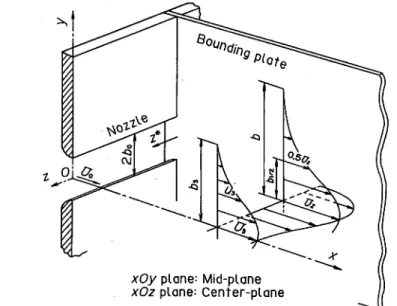
A schematic model of a bounded jet flow and the symbols are shown in Fig.l. Let the origin 0 be taken
at the center of the nozzle exit, the axis of x in streamwise direction, and the axes of y and z perpen
dicular to the axis of x, respectively, as shown in the figure. Let z* be the distance from the bounding
plate. The xOy plane is defined as the mid-plane of the bounded jet flow and the xOz plane as the cen
ter—plane of it.
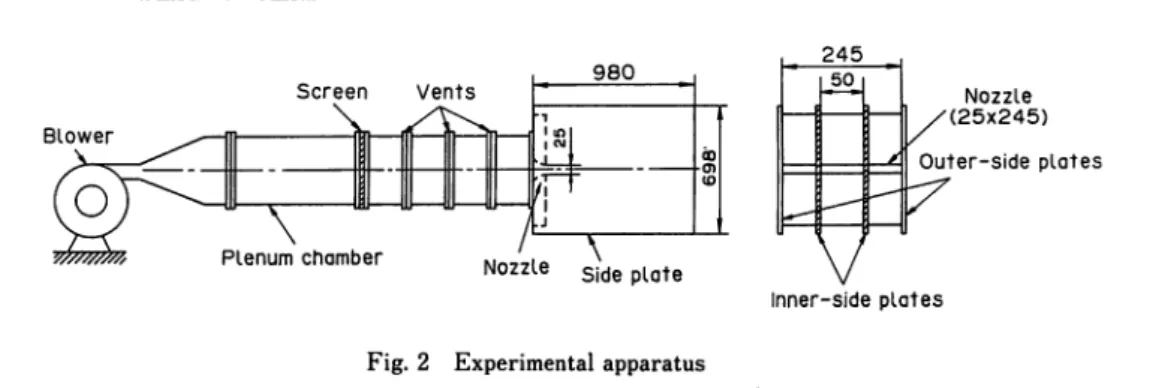
The outline of the experimental apparatus is shown in Fig.2. The air supplied from the centrifu
gal blower (the static pressure 9.8 kPa) passes through three stainless steel screens (8- to 30-mesh)
in the plenum chamber to suppress the flow turbulence and issues from the nozzle with a uniform
velocity. The velocity Uo at the nozzle exit is 18m/s and the nozzle width 2bo is 25mm, the
corres-xOy plane: Mid-plane xOz plane: Center-plane
Blower
Experimental Study of Turbulence Properties for a Bounded Jet Flow 11
980
Nozzle
Fig. 2 Experimental apparatus
245 50 /' Nozzle '(25x245) Outer-side plates Inner-side plates
ponding exit Reynolds number Re is 3.0 X 10⁴. The turbulence intensity at the nozzle exit, that is, the
initial turbulence intensity To, is varied by controlling the width of the vent and the mesh of screens.
In this experiment To is set to be 0.008.
In this experimental apparatus, two inner side plates are placed between two outer side plates, as shown in Fig.2, and these inner side plates act as the bounding plates. The flow between these bound ing plates is measured. The ratio of the distance 2H between the bounding plates to the nozzle width
2bo is defined as the nozzle aspect ratio H/bo. Various nozzle aspect ratios are easily obtained by
changing the distance between the bounding plates. By using such apparatus, the initial turbulence in tensity is held almost constant regardless of the nozzle aspect ratio, since the whole flow rate from the nozzle section is kept constant. In this experiment, the nozzle aspect ratio is 2. This is due to the
following reason; it has been already found that the flow pattern of the reattachment jet flow[12] and
the turbulence properties of the bounded jet flow[10] change greatly near this nozzle aspect ratio. The measurements of the velocity, the turbulence intensity and the Reynolds stress were done by
using the 2—channel hot—wire anemometer system (KANOMAX, 7000 series) and the X—type wires (5
fim diameter—tungsten, 1mm wire distance and 1mm effective length). The X—type wires were set so
that the plane formed by two wires was parallel to the mid—plane of the bounded jet or the
center-plane of it.
EXPERIMENTAL RESULTS AND DISCUSSION Turbulence properties in the mid-plane of the jet
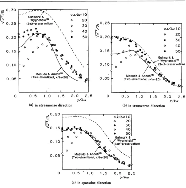
In Fig.3 the streamwise variations of the turbulence intensities in each axial direction normalized by the velocity £/3 on the jet center axis are shown against y which is normalized by the half—value width b\/2 of the jet.
The intensity v i/2/[/3 shown in Fig.3 (a) increases at the beginning of the flow. It has the max
imum value at the downstream location about x/b0 = 30 or 40 and then decreases gradually. Further
more, these distributions are fairly different from that of Gutmark and Wygnanski[13], which has been obtained in the state of self—preservation. This fact is related to the boundary layers developing on the bounding plates. It has been found from the calculations^4] that these boundary layers reach the mid—plane at the downstream location x/6q = 32.3 in the case of H/bo= 2. Therefore, from these ex perimental results shown in Fig.3 (a), it becomes clear that the boundary layer has a considerable
effect on the distribution of v u2/Uz in ^direction, not only on the distribution in the center—plane
of the jet, as Nakashima et al.[9] discussed before.
Furthermore, at the downstream location x/b0=20 the turbulence intensity is compared with that
^0.30
0 . 2 5 - 0 . 2 5 0 . 2 0 0 . 15 0. 15 0 . 10 0 . 10 9i \
ox/bo=]0 e 20 © 30~ o 40 • 50H Gutmark & ;(I3) $^^ Wygnanski"1 ^ N (Self-preservation) X- ^ I — l i---"
/ n
o X/bo= 1 0 Gutmark & \ Wygnanski"3' NN e 20\
©
30~
(Self-preservation) \ o 40 r • >"?^e u • x e *\p \ •50-/e
T
\9
°
° d
\ <r o \ \V *
o\ °
\
\ »
\
-" oX
8
*
9 / \ eoMasuda & Andoh"8' \ • a
(Two-dimentionaI, x/b^oX. e§ ^
" • i i
0 . 0 5 - 0 . 0 5
Masuda & Andoh(,8) (Two-dimentional, x/bo=
0 . 5 1 .0 1 . 5 2 . 0 2 . 5
y/bw (a) in streamwise direction
_l_ 0 . 5 1.0 \ / Wygnanski"" MSelf-preservation) 0 . 10 0 . 0 5 -o / Nfc o
Masuda & Andoh"' (Two-dimentional, x/bo=20)"
0 0.5 '1.0 1.5
(c) in spanwise direction
Fig. 3 Streamwise variation of the turbulence intensity
_]_ 1 . 5 •**1 2 . 0 2 . 5 y/bt/g (b) in transverse direction
is smaller and the intensity in y/6i/2<1.0 is larger than that of the two—dimensional jet. These facts correspond to the distribution of the production term of turbulence energy, which will be discussed
later.
Next, distributions of the turbulence intensity V v2/Uz are shown in Fig.3(b). In contrast to the
distributions of V u2/U& V «/2/[/3 increases downstream monotonously and tends to approach the re
sult of Gutmark and Wygnanski [13]. Furthermore, the distribution at x/bo±?20 is similar to that of a two—dimensional jet flow. It can be seen from these results that the velocity fluctuation v in y—direc tion is independent of existence of the bounding plates. Consequently, it is found that the fluctuation
v has relatively large effect upon the flow field, considering that the distribution of v u2/Uz depends
somewhat upon the bounding plates.
Experimental Study of Turbulence Properties for a Bounded Jet Flow 13
bounding plates, the distributions of v w2/Uz are small as a whole, comparing with the distribution of
V u2/ Us shown in Fig.3 (a) and v v2/ Uz in Fig.3 (b) at each downstream location. They are similar
each other in the range of x/bo > 30. This is due to the fact that in this range the boundary layers developing on the bounding plates reach the mid—plane and distributions of the velocity Uz on the jetcenter—plane are similar each other regardless of the downstream location.
Next the turbulence intensity in each axial direction obtained above and the distributions of the auto—correlations of u, v and w\ which have been reported by Nakashima et al.[10], will be discussed
together.
At the downstream location near the nozzle exit, the order of magnitude for the turbulence in
tensity is Vu2/Uz > V v2/Uz^=r Vw2/Uz- Therefore, this flow field is the cigar—type turbulent flow
field having the axis in x—direction and is similar to that of Makita et al.[16]. They investigated the anisotropy of turbulent flow field and the process to the isotropy of it, by using an artificial turbu lence generator to realize a strong turbulence flow field with large scale eddies in small wind tunnel. Thus free turbulence is predominant in the region near the nozzle exit.
At the location further downstream, the boundary layer develops gradually and its effect extends to the fluctuation w first and to u succesively. Thus, the order of magnitude for the turbulence in
tensity varies gradually such as Vu2/Uz =N= Vv2/Uz > ^1 to2/ Uz* The type of the turbulent flow field
changes from the cigar—type to the pancake—one little by little. This pancake—type flow field has the axis in z—direction and is different from that of Uberoi[17], where the energy transfer in isotropic turbulence has been investigated by using the low turbulence wind tunnel behind one inch square mesh
biplane grid. Furthermore, the flow field has the axis in x—direction and the order of magnitude is
n^/uz <-Hp/Uz # JV*/ih.
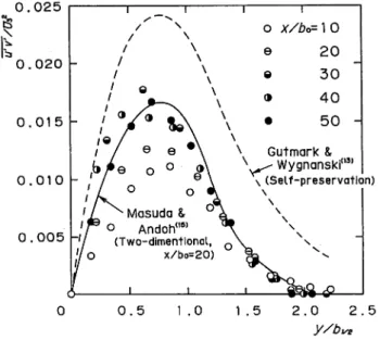
Next, distributions of the Reynolds stress uv are shown in Fig.4. It is clear from this figure that the stress uv is fairly small as a whole, compared with the results of Gutmark and Wygnanski[13] and Masuda and Andoh[15], This is due to the velocity normalizing the Reynolds stress.
0.025
s
0 . 0 2 0 0.015 0 . 0 1 0 0 . 0 0 5-0.005 <r -0.010 -0.015 ^p"" F"' ' J^^rd^o-•QD 1
^ O
/&
\eo % o e x / bo=10 20\# °J
Q 303^twx<
3 40 V\f • 50 Q Masuda &Andoh(M5> (*//>o=16) i i i 1 0.5 1.0 1.5 2.0 2.5 y/bu2Fig. 5 Production term of turbulent energy
Namely, since the velocity Uz on the jet center axis of the bounded jet flow is influenced by the dis placement of the boundary layer, Uz decreases more slowly than the velocity U^ on the jet center line of a two—dimensional jet flow, so that Uz is larger than U% at the same downstream location. On the other hand, the Reynolds stress uv is normalized by the velocity Uq at the nozzle exit, so the magni tude of the stress is discussed. The Reynolds stress of the bounded jet flow is larger than that of the
two—dimensional one in the range of 1.3 < y/b\^ Since the velocity distribution of the bounded jet flow is so called a cross—over type, as pointed out by Holdeman and Foss[3], the velocity gradient of the bounded jet flow is larger than that of a two—dimensional one. As a result, this effect appears a
little in the distribution of the Reynolds stress.
Next, one of the production terms of turbulence energy, the term uv (3 u /3y) is discussed in this paper. The spline function of the third order is used for the estimations of the velocity gradient 3 u / 3 y. The production term is shown in Fig.5, normalized by the velocity Uz and the half—value width bi/2 of the jet. The solid line in this figure shows the values at the downstream location x/bo
= 16 in a two—dimensional jet flow, as mentioned previously. Strictly speaking, this line shows uv
X |( 3 u/ 3 y) + (3 v/ 3 x)\ , so this line is shown only for reference. The magnitude of the term uv
X(3 u/3 y) becomes maximum near the downstream location x/60= 30. This fact corresponds well to
that the turbulence intensity J u2/U3l as shown in Fig.3 (a), has the maximum value at this down
stream location. Moreover, regardless of the downstream location, in the range of y/b\/2 > 1.0 their magnitude are larger than that shown by the solid line which is for a two—dimensional jet flow. Thisis due to that the turbulence intensity Vu2/U3 is larger than that of a two—dimensional jet flow in
this range.Turbulence properties in plane parallel to the mid-plane
In previous investigations concerning the bounded jet flow, the flow field near the nozzle exit was
studied. For example, in the approximate calculations[18,19] of the mean velocity field, the calculated
results were compared with the experimental results at the downstream location x/bo=20. Therefore,
in this paper the turbulence properties in plane parallel to the mid—plane of the bounded jet flow were obtained at the same downstream location and the similarity of the distributions of these prop
erties are discussed.
Illustration of the distributions of turbulence intensities Vu2/Uz and Vw2/Uz are omitted here,
because it is easy to understand that these intensities are small in the region near the bounding plates and these distributions become similar to those in the mid—plane gradually as the measuring plane
Experimental Study of Turbulence Properties for a Bounded Jet Flow 0 . 2 0 0 . 1 5 1 1 <?Oo I i o > e 3nl&B#?R^m _
a—&--?^®^©(few»
T \ ^ ^\
^Vu
Masuda & <^\<fa
Andoh(,9)
<S
\% ~ (Two-dimentional, x/bo=20) z*/bc z*/bo o =0.2 o) =1 .2"^^a
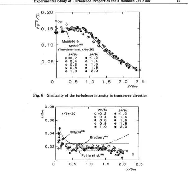
© 0.4 © 1.4 ^ © 0.6 © 1.6 © 0.8 © 1.8 © 1 . 0 • 2.0 I I i 0 . 1 0 -0 . -0 5 0 . 5 1 . 0 1 . 5 2 . 0 2 . 5 y/bx/2Fig. 6 Similarity of the turbulence intensity in transverse direction
0 . 0 8 0 . 0 6 -z*/bo x/fco=20 O =0.2 e 0 . 4 © 0 . 6 © 0 . 8 © © i.o
_^x
lshlgaki<20)
©^/
Bradbury'20
Z*/6o • =1.2 © 1 . 4 © 1 . 6 © 1 . 8 • 2 . 0 Fujita et al.ww i i i 0 . 0 4 0 . 0 2 -0 . 5 1 . 0 1 . 5 2 . 0 2 . 5 y/bi/zFig. 7 Spanwise variation of the mixing length
15
approaches this plane. In contrast with the distributions of turbulence intensities Vu2/Uz and v w2/
Uz, the distributions of
V v2/U^ shown in Fig.6 are almost similar in each plane, except
z*/60 = 0.2 and 0.4. Furthermore, it is interesting that the distribution of Jv2/U3 is also similar to
that of a two—dimensional jet flow. Considering these results together with the facts discussed in the previous section, it can be seen that the velocity fluctuation in y—direction is hardly influenced by the bounding plates over the wide range of the flow field. Consequently, the diffusion of the flow is promoted even in the vicinity of the bounding plates. This fact also supports the striking feature of the velocity of the bounded jet being large near the bounding plates.The Reynolds stress uv was also measured in these planes. By using this stress and the velocity gradient 3 u/ 3 y, the mixing length i , which is often used in modeling for the turbulent flow field, was estimated. This result is shown in Fig.7, normalized by the half—value width of the jet. The length i/bi/2 is slightly smaller than the result calculated by Ishigaki[20] as well as the experimental result of a two—dimensional jet flow issuing from the cruciform nozzle[22]. It can be seen from this fi gure that values of t/bi/2 vary little in ^-direction and that the scatter is fairly small. Consequently,
except the regions of the center part and the outer part of the jet, the length I /b\/2 in the bounded jet flow may be assumed to be 0.18 for calculation of the turbulence flow regardless of the spanwise
location.
Turbulence properties in the cross section normal to streamwise direction
At the downstream location x/bo = 20, the contour lines of the turbulence properties were obtained in
the cross section normal to streamwise direction.
The secondary flow is shown in Fig.8, by using the velocity vector diagram obtained from the measurements of the time—averaged velocity components v and w in y- and z—direction, respectively. For the sake of reference, the contour lines of the velocity of the main flow are also shown in this figure. In the region near the bounding plates, the flow from the center part to the outer part of the jet is generated. On the other hand, in the region close to the mid—plane, the flow occurs from the outer part of the jet toward the center part because of the flow entrainment. From these two flows a
large scale swirl is generated around the point (y/bo = 2.2, z*/bo == 1.0). Consequently, the contour
lines of the velocity are deflected considerably toward the bounding plates because of this large scale swirl. Nozaki et al.[5] have found from the experiment for the case H/bo = 1 that at the location x/bo = 10 this swirl exists in the vicinity of the bounding plates. Considering their results together with
the results obtained in this paper, this swirl develops step by step and largely affects the whole flow field.
The contour lines of the turbulence intensity in each axial direction were obtained in this cross
section. Since they are fairly similar to the contour lines of the turbulence energy
-<l'2 = ^(u'2+v'2 + w'2),
5 . 0 4 . 5 4 . 0 3 . 5 -3 . 0 2 . 5 2 . 0 1 . 5 1 . 0 -0 . 5Experimental Study of Turbulence Properties for a Bounded Jet Flow 17
only this energy is shown in Fig.9. The maximum value of the turbulence energy locates in the range of 0.9 < y/bo < 1.7 and 0.8 < z /bo < 2. 0. The secondary flow affects the local excess of the con
tour lines of the velocity in the case of free turbulence[23]. Meanwhile, it affects the local excess of the contour lines of the turbulence intensity for wall turbulence[24]. Taking account of these facts, in this experiment the effects of the secondary flow appear in both contour lines to the same degree. This is due to the fact that wall turbulence predominates in the vicinity of the bounding plates and
free turbulence predominates in the region near the mid—plane.
The contour lines of the Reynolds stress in this cross section is shown in Fig.l0. The maximum
value of uv locates in the region of 1.0 < y/bo < 1.8 and 0.9 < z*/bo < 2.0 and this location corre
sponds well to that showing the maximum value of the turbulence energy. This location also corre
sponds to the place where the velocity gradient | 3 u/3y\ shows the maximum value.
It has been found by Foss and Jones[25] that the contour lines of the velocity are largely dis
torted in the region near the bounding plates unlike those of a two—dimensional jet. In order to in vestigate this phenomenon, Holdeman and Foss[3] measured the streamwise vorticity component near the nozzle exit, by using the vorticity meter. However, this result does not give the quantitative in formation perfectly. In this paper the streamwise vorticity
n* =
3 w 3 v
3 y 3 z
was calculated by using the time—averaged velocity components v and w obtained in the previous sec tion. The contour lines of the vorticity is shown in Fig.l 1, normalized by the velocity Uz on the jet
5 . 0 \ 4 . 5 4 . 0 3 . 5 3 . 0 2 . 0 1 . 5 1 . 0 0 . 5
Fig. 9 Contour lines of the turbulence energy (x/bo = 20) 4 . 5 -4 . 0 3 . 5 3 . 0 2 . 5 -2 . 0 1 . 5 1 . 0 0 . 5 0.5. o . o i o 0.008 0.006 0.004 0.002 1.5 2.0 z*/bo
Fig. 10 Contour lines of the Reynolds shear stress (x/bo = 20)
5 . 0 4 . 5 4 . 0 3 . 5 -3 . 0 &#-34; 2 . 5 2 . 0 1 . 5 1 . 0 0 . 5
Fig. 11 Contour lines of the vorticity (x/bo ~ 20)
center axis and a half width bo of the nozzle exit. The positive vorticity is distributed widely around
the point (y&0 =2.8, z*/bo = 0.5) and these contour lines of the vorticity are largely stretched out in
^direction. In addition to this, there exist two small scale negative vorticity regions near the
mid-plane and the center-mid-plane, respectively. In the region near the center-mid-plane, the displacement from
the bounding plates and the large scale swirl interact mutually. In the region near the mid-plane, the
entrainment and this swirl interact each other. Existence of the vorticities having different signs have
been recognized in the paper of Holdeman and Foss[3].CONCLUSIONS
In the mid-plane of the bounded jet flow, distributions of turbulence properties such as the turbu
lence intensity, the Reynolds stress, the production term of turbulence energy, which have been hardly
investigated in a bounded jet flow, were measured by using an apparatus having a nozzle aspect ratio
of 2. These properties were compared with those of a two-dimensional jet flow in the initial mixing
region and in the self—preserving region, respectively.As a result, in the mid—plane it has been found that the turbulence intensities in streamwise and
spanwise directions are considerably influenced by the bounding plates for fairly downstream location.
On the contrary, it has been made clear that the turbulence intensity in transverse direction is hardly
influenced by the bounding plates and affects the flow field.Turbulence properties on the plane parallel to the mid-plane were also measured and their simi
larity toward spanwise direction were investigated. As a result, it has been found that the distribu
tions of the turbulence intensity in transverse direction are similar over the wide range of the flow
field. Moreover, they are also similar to the distribution in the initial mixing region of a
two—dimen-Experimental Study of Turbulence Properties for a Bounded Jet Flow 19
sional jet flow.
Next, the contour lines of the turbulence energy and the Reynolds stress were obtained in the
cross section normal to streamwise direction. Their distributions correspond well with each other
over the wide range of the flow field. Furthermore, the time—averaged velocity components of the
secondary flow in each axial direction were measured. The secondary flow generating in the bounded
jet flow was indicated by the velocity vector diagram. Moreover, the contour lines of the vorticity
were obtained by using these results. These lines are largely stretched out in transverse direction. It
has been recognized that there exist two regions where vorticity has different signs.
NOMENCLATURE 2bo Nozzle width, mm
bi/2 Half value width of the jet, mm
H/bo Nozzle aspect ratio, dimensionless
I
Mixing length (I2 =- mV /((3 u/3 y) \ 3 u/ 3 y | ), mm
Re Reynolds number, dimensionless
To Initial turbulence intensity, which is the RMS value of u normalized by the velocity l/o,
dimensionless
Uo Mean velocity at the nozzle exit, m/s
U3 Mean velocity on the jet center axis, m/s
U2 Mean velocity on the jet center line for a two—dimensional jet flow, m/s vtw Mean velocity component in y— and z—direction, respectively, m/s
u,v,w Fluctuation component of the velocity in x =, y = and z—direction, respectively, m/s
uv Reynolds shear stress, m2/s2
xfy,z Cartesian streamwise, transverse and spanwise co-ordinates, respectively, mm z Distance from the bounding plate, mm
Ox Vorticity component in x—direction, 1/s
REFERENCES
1) Iwata, H., et al., Study of Refrigerant Distributor Making Use of Fluidics in Refrigeration Cycle, Trans. Jpn. Soc. Mech. Eng. (in Japanese), Vol.52, No.475, B(1986), p.1394.
2) Yonezawa, Y., et al., Ignition by a Flame Jet Ejected from a Narrow Channel, Trans. Jpn. Soc. Mech. Eng. (in Japanese), Vol.52, No.475, B(1986), p.1118.
3) Holdeman, J. D. and Foss, J. F., The Initiation, Development, and Decay of the Secondary Flow in a Bounded Jet, Trans. ASME, J. Fluid Eng., (1975), p.342.
4) Mamiya, T., et al., The Effect of Initial Turbulence and Aspect Ratio on Internal Jet Behavior, Prepr. 14th Fluidics Symp. (in Japanese), (1979), p.l.
5) Nozaki, T., et al., Experimental Study of a Bounded Jet Flow (Mechanism of the Secondary
Flow), Proc. 4th Int. Symp. Flow Visual., (1986), p.495.
6) Nozaki, T., et al., Study of a Bounded Jet Flow Considering the Initial Turbulence (Experiments with a Nozzle Having Aspect Ratio of 3), Bull. Jpn. Soc. Mech. Eng., Vol.27, No.234, (1984), p.
2730.
7) Abe, J., et al., The Effect of Different Shapes of Nozzles Affected on the Spread of a Bounded Jet, Prepr. 17th Fluidics Symp. (in Japanese), (1982), p. 1.
Fluid—Amplifier—Type Jets, Trans. ASME, J. Dynamic System, Measurement, and Control,
(1971), p. 53.
9) Nakashima, M., et al., Study of a Bounded Jet Flow Considering the Initial Turbulence (4th Re port, Turbulence Properties for the Nozzle Aspect Ratio of 2), Trans. Jpn. Soc. Mech. Eng. (in Japanese), Vol. 54, No. 503, B(1988), p. 1622.
10) Nakashima, M., et al., Effects of a Nozzle Aspect Ratio on the Turbulence Properties of a Bounded Jet Flow Considering the Initial Turbulence, Proc. 4th Asian Congress of Fluid Me
chanics, Vol. 1, (1989), p. A93.
11) Nakayama, Y. and Ogino, H., Characteristics of the Turbulent Flow Field in a Wall Attachment Device (In the case of No Control Port One Output Port Closed), Trans. Jpn. Soc. Mech. Eng. (in Japanese), Vol. 52, No. 473, B(1986), p. 34.
12) Nozaki, T., Reattachment Flow Issuing from a Finite Width Nozzle (4th Report, Effects of Aspect Ratio of the Nozzle), Bull. Jpn. Soc. Mech. Eng., Vol. 26, No. 221, (1983), p. 1884. 13) Gutmark, E. and Wygnanski, I., The Planar Turbulent Jet, J. Fluid Mech., Vol.73, (1976), p. 465. 14) Nakashima, M., et al., Study of a Bounded Jet Flow Considering the Initial Turbulence (2nd Re port, In the case of Relatively Large Nozzle Aspect Ratio), Bull. Jpn. Soc. Mech. Eng., Vol. 29,
No. 253, (1986), p. 2042.
15) Masuda, W. and Andoh S., Hot—Wire Measurements in the Initial Mixing Region of a Plane Jet, Trans. Jpn. Soc. Mech. Eng. (in Japanese), Vol. 54, No. 497, B(1988), p. 45.
16) Makita, H., et al., Evaluation of the Characteristic Features of a Large—Scale Turbulence Field (3rd Report, on the Scales and the Anisotropy of the Turbulent Flow Field), Trans. Jpn. Soc. Mech. Eng. (in Japanese), Vol. 54, No. 497, B(1988), p. 37.
17) Uberoi, M. S., Energy Transfer in Isotropic Turbulence, phys. Fluids, Vol. 6, (1963), p. 1048. 18) Nakashima, M., et al, Study of a Bounded Jet Flow Considering the Initial Turbulence (3rd Re
port, A Method of Approximate Calculations for the Mean Velocity Field), Trans. Jpn. Soc. Mech. Eng. (in Japanese), Vol. 52, No. 478, B(1986), p. 2367.
19) Nakashima, M., et al., Study of a Bounded Jet Flow Considering the Initial Turbulence (Report 3, Effects of the initial Turbulence on the Shape Parameter), Theoretical and Applied Mechanics, Vol. 37, (1989), p. 63.
20) Ishigaki, H., A Numerical Calculation of Turbulent Jet, J. Jpn. Soc. Aerosp. Sci. (in Japanese), Vol.28, No. 313, (1980), p. 102.
21) Bradbury, L. J. S., The Structure of a Self-preserving Turbulent Plane Jet, J. Fluid Mech. Vol. 23, No. (1965), p. 31.
22) Fujita, S., et al., Three—Dimensional Jet Issuing from the Cruciform Nozzle (2nd Report, Turbu lence Properties), Trans. Jpn. Soc. Mech. Eng. (in Japanese), Vol. 51, No. 467, B(1985), p. 2281. 23) Osaka, H., et al., The Structure of Turbulent Wake Behind a Cruciform Circular Cylinder (2nd
Report, The Streamwise Development of Turbulent Flow Fields), Trans. Jpn. Soc. Mech. Eng. (in Japanese), Vol. 48, No. 432, B(1982), p. 1456.
24) Furuya, Y., et al., Turbulent Boundary Layer Along a Streamwise Bar of a Rectangular Cross Section Placed on a Flat Plate, Trans. Jpn. Soc. Mech. Eng. (in Japanese), Vol. 42, No. 359,
B(1976), p. 2091.
25) Foss, J. F. and Jones, J. B., Secondary Flow Effects in a Bounded Rectangular Jet, Trans.