Electrical Conductivity-Relay between Organic
Charge-Transfer and Radical Salts toward
Conductive Additive-Free Rechargeable Battery
著者
Yui Fujihara, Hiroaki Kobayashi, Shinya
Takaishi, Takaaki Tomai, Masahiro Yamashita,
Itaru Honma
journal or
publication title
ACS Applied Materials & Interfaces
volume
12
number
23
page range
25748-25755
year
2020-05-15
URL
http://hdl.handle.net/10097/00131801
doi: 10.1021/acsami.0c036421
Electrical Conductivity-Relay between Organic
Charge-Transfer and Radical Salts toward
Conductive Additive-Free Rechargeable Battery
Yui Fujihara,†,‡ Hiroaki Kobayashi,*,† Shinya Takaishi,‡ Takaaki Tomai,†
Masahiro Yamashita,‡,§,∥ and Itaru Honma†
†Institute of Multidisciplinary Research for Advanced Materials, Tohoku University, 2-1-1
Katahira, Aoba-ku, Sendai, Miyagi, 980-8577, Japan.
‡Department of Chemistry, Graduate School of Science, Tohoku University, 6-3
Aramaki-Aza-Aoba, Sendai 980-8578, Japan.
§WPI Research Center, Advanced Institute for Materials Research, Tohoku University, 2-1-1
Katahira, Aoba-ku, Sendai 980-8577, Japan.
2 ABSTRACT
In recent years, organic electrode materials have been strongly considered for use in sustainable batteries. However, most organic electrode materials have low electrical conductivity and require a lot of conductive additives, which decrease effective capacity based on the entire electrode weight/volume. In this study, we propose a novel electrical conductivity-relay system that imparts electrical conductivity to organic small molecular electrodes without any conductive additive throughout the charge/discharge cycles. It consists of the combination of the charge-transfer phenomenon in a pristine state and the formation of organic radical salts in redox states. Herein we demonstrate this electrical conductivity-relay system using a simply mixed molecular crystal couple of tetrathiafulvalene (TTF) and tetracyanoquinodimethane (TCNQ) as a cathode without any conductive additive and an aqueous sodium bromide as an electrolyte. During charge/discharge, electrical conductivity of the cathode is supported by charge-transfer at the TTF/TCNQ interface and (TTF)Brn and NaTCNQ radical salts, and the cathode exhibits the
specific capacity of 112 mAh g–1 and the retention rate of 80.7% at the 30th cycle. Furthermore,
the molecular crystal couple electrode of TTF and TCNQ shows the better charge/discharge performance than the pure charge-transfer complex electrode, indicating that this system expands the candidate for organic electrode materials to various pairs and mixing ratio of small molecules even not forming charge-transfer complexes.
KEYWORDS
3 INTRODUCTION
Secondary batteries are widely used in society today (e.g., portable devices, EVs, and stationary power supplies), and demand for these batteries is increasing considerably with economic growth. However, most contemporary batteries contain minor metals such as nickel and cobalt in their electrodes. Therefore, researches on more sustainable secondary batteries have been essential and actively pursued in recent years. Organic electrode materials, which use redox-active organic compounds as active materials, are attracting attention as an alternative to conventional inorganic electrodes.1-5 They have further advantages over inorganic materials as shown below:
l Various molecular designs due to high susceptibility to chemical modification.
l Synthesized under mild conditions consuming less energy during synthesis compared with inorganic materials.
l High specific capacity derived due to multiple redox reactions.
l Structural flexibility for insertion of the large carrier ions applicable to next-generation batteries such as sodium ion batteries and zinc ion batteries.3, 6, 7
Notably, batteries that utilize organic electrodes and an aqueous electrolyte are promising because they offer safety, robustness, and environmental friendliness.6, 8-11 However, there is the critical
drawback of low electrical conductivity, such that most of these electrodes require a significant amount of conductive additives, resulting in a low effective capacity based on the entire electrode weight/volume. Furthermore, there are problems of high elution to the electrolyte and low cycle stability. Although there have been various researches conducted on organic electrode materials, the materials that perform charge/discharge without the addition of a lot of additives are limited to
4
a few conductive polymers such as polyaniline (PANI), polythiophene (PTh), and polypyrrole (PPy).12, 13 To the best of our knowledge, the charge/discharge without any conductive additive
has not been achieved in small molecular compounds. Conductive polymers are highly promising materials in terms of good stability and electrical conductivity,4 but polymerization often requires
a complicated synthetic process and it limits the candidates for an electrode material. Polymerization also gives rise to a decline of capacity due to increase in the formula weight via polymerization. Hence, the exploration for simple methods other than polymerization that impart electrical conductivity to small organic molecular materials is crucial for opening up a future for research on organic electrode material.
The application of organic conductors in battery electrodes is one of the solutions to considerably improving the electrical conductivity of small organic molecules. Organic conductors are commonly employed in the fields of sensors and organic electronics, and their electrochemical behavior has been extensively studied, but they have not been successfully utilized in battery electrodes.14-18 Very recently, in one of the very few reports of such a strategy, Lee et al. reported
using organic charge-transfer (CT) complexes as cathodes in a lithium ion battery to enhance electrical conductivity.19 The CT phenomenon is well known in the field of organic electronics,
and in many cases, it enhances electrical conductivity by transferring an electron from a donor molecule to an acceptor molecule. Although electrical conductivity of the organic cathode was enhanced in that study, a decline in specific capacity was observed as the amount of conductive additive decreased, which indicates that the electrical conductivity of the active material is insufficient. This insufficient electrical conductivity is probably attributable to the electrical conductivity of the CT complex decreasing significantly during charge-discharge reactions by change in its electronic state. Thus, electrical conductivity needs to be maintained both in the
5
pristine state and in the redox states (states during charge/discharge reaction) to solve the problem of the low electrical conductivity of organic electrodes.
To maintain the electrical conductivity of organic electrodes both in the pristine state and the redox states, we developed a cathode system in which the electrical conductivity of different redox states is supported by several mechanisms. To achieve a mechanism that imparts electrical conductivity to even small molecular compounds, we focused not only on the charge-transfer
phenomenon for the electrical conductivity in the pristine state, but also organic radical salts for
the electrical conductivity in the redox states. As for the pristine state, there are two types of charge-transfer phenomena: one is CT complex as reported which is a co-crystal of donor and acceptor molecules20-22 and the other is the occurrence of charge-transfer at an interface without
any particular change to the crystal structure.23, 24 The latter phenomenon occurs when the donor
and acceptor particles are physically in contact with each other. So, it enables various donor/acceptor couples of molecular crystals to apply organic electrodes by a very simple method of mixing the crystalline particles to impart the electrical conductivity. Conversely, organic
radical salt is a crystal salt made from a molecular radical and small inorganic ions. When an
organic radical salt creates a particular crystal packing and structure, it has a good electrical conductivity due to its electronic state. Some of the materials in the organic radical salt can be used as the redox states of an electrode material because they are generated by direct electrochemical insertion of small ions into organic crystals.18, 25-28 Therefore, in combining the charge-transfer
phenomenon as a conductor for the pristine state with the organic radical salt as a conductor for the redox states, the electrical conductivity of the entire electrode material can be synergistically increased and maintained to achieve a conductive additive-free organic electrode material of small molecular compounds.
6
In this study, we demonstrate this electrical conductivity-relay concept by providing continuous electrical conductivity to organic electrodes without any conductive additive using the well-known donor/acceptor molecules of tetrathiafulvalene (TTF) and tetracyanoquinodimethane (TCNQ), with aqueous sodium bromide solution as the electrolyte. Though TTF and TCNQ themselves are insulators (10–12 S cm–1 and 10–10 S cm–1, respectively),19, 29 they give rise to
charge-transfer between themselves,20, 23 and both TTF and TCNQ form organic radical salts with
bromide ion and sodium ion electrochemically, respectively.30, 31 The schematic mechanism is
illustrated in Figure 1. As a pristine state, crystals of TTF and TCNQ are mixed and bound together to form the Molecular Crystal Couples (MCC) cathode. The electrical conductivity derived from the charge-transfer phenomenon occurs at the interfaces between TTF crystal and TCNQ crystals to promote the first charge step. Second, bromide ions are inserted into TTF to make a conductive radical salt, (TTF)Brn (0.7 ≤ n ≤ 0.8; electrical conductivity ≈ 102 S cm–1) during charge.28, 30 The
high electrical conductivity of the entire electrode is maintained by this salt rather than the charge-transfer phenomenon. During discharge, (TTF)Brn is reduced to TTF to recover the charge-transfer
phenomenon at interfaces, followed by TCNQ reduction to form NaTCNQ with sodium insertion. Although this NaTCNQ is not as highly conductive as (TTF)Brn, this electrical conductivity is
about 105 times higher than that of pure TCNQ. Hence, the formation of NaTCNQ also supports
the electrical conductivity of the entire electrode. Therefore, these three mechanisms: charge-transfer between TTF and TCNQ, and the organic salts of (TTF)Brn and NaTCNQ, function as
7
Figure 1. Schematic illustration of the relay of electrical conductivity via the charge-transfer
phenomenon and organic radical salts using tetrathiafulvalene (TTF) and tetracyanoquinodimethane (TCNQ) and aqueous NaBr electrolyte.
8 EXPERIMENTAL SECTION
Reagents: TTF (>98.0%) and TCNQ (>98.0%) were purchased from Tokyo Chemical Industry
Co., Ltd. and other chemicals were purchased from FUJIFILM Wako Pure Chemical Corporation. All chemical reagents were used without further purification.
Electrode fabrication: For the typical fabrication of TTF-TCNQ MCC cathode, TTF (20 mg,
0.098 mmol) and TCNQ (20 mg, 0.098 mmol) were ground together in an agate mortar and a pestle for about 20 minutes. Note that their molecular weights are almost same (204.34 g mol–1 and
204.19 g mol–1, respectively), so their weight ratio was almost 1:1. The mixture was further ground
with 3 mg of polytetrafluoroethylene (PTFE) for about 10 minutes so that the weight ratio of TTF:TCNQ:PTFE was 46.5:46.5:7. Thus obtained sheet was cut into 7 mm diameter disk of typically 6.5 mg and pressed on an Au mesh current collector (10×10 mm, 100 mesh) at 4 kN to serve as the cathode. As a control, TTF cathode, TCNQ cathode, and TTF-TCNQ charge-transfer (CT) complex cathode were fabricated using TTF, TCNQ, or TTF-TCNQ CT complex (93wt%) and PTFE (7wt%) in the same way. The TTF-TCNQ CT complex was synthesized as reported.20
For conductive carbon added cathodes, the organic active materials (46.5wt%) were blended with acetylene black (AB, 46.5wt%) and PTFE (7wt%).
Material Characterization: The electrical conductivity of pristine TTF-TCNQ MCC cathode was
measured at 300 K in Quantum Design PPMS (Physical Property Measuring System) MODEL 6000 by using the four-probe method. The electrical leads were attached to a single crystal with carbon paste (Dotite XC-12 in diethyl succinate). To check the reproducibility, we performed the measurements on 12 times (3 different pellets). Raman spectra were measured in HORIBA, LabRAM HR-800 using 532 nm laser. XRD measurements were performed using Bruker D8
9
advance. SEM-EDX was performed in JEOL JSM-6010LA and JSM-7800F with acceleration voltage of 10 kV.
Electrochemical measurements: Electrochemical tests were performed in Biologic VMP-3 with
three electrode cell using 1 M NaBr aqueous electrolyte and a single junction Ag/AgCl reference electrode (+0.199 V vs. SHE) with internal saturated KCl solution separated by porous glass. Fabrication of working electrode was described above. Counter electrode was fabricated with activated carbon (Maxsorb MSC-30), AB, and PTFE in the weight ratio of 8:1:1, pressed on Au mesh current collector. For the electrochemical cell, the electrolyte was treated with 2 hours of N2
bubbling before use. The working electrode and the counter electrode were immersed in the electrolyte and the cell was vacuumed for 30 minutes to remove air inside the electrodes. All measurements were performed with N2 bubbling at 25ºC. Each measurement started just after open
circuit voltage for 30 minutes. As for charge-discharge cycle test, cut off potential was from – 0.6 V to 0.6 V, and current density was 524 mA g–1. All capacity values in this study are calculated
as the specific capacity per gravimetric amount of active material. CV was performed in the same voltage range, oxidation first, and sweep speed was 5 mV sec–1. Electrochemical impedance
spectroscopy (EIS) measurements were performed using 10 mV amplitude in the frequency range from 100 kHz to 1 Hz. The obtained EIS data were analyzed using Zview software.
10 RESULTS AND DISCUSSION
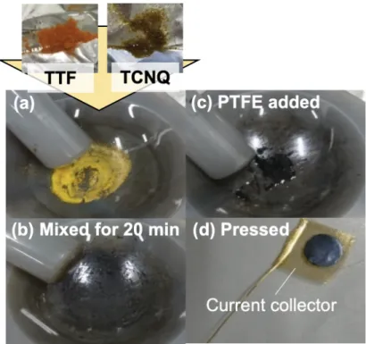
The MCC cathode was fabricated by simple mixing of equimolar ratio of TTF and TCNQ crystals using an agate mortar and a pestle. Orange TTF powder and brown TCNQ powder were ground together, followed by compositing with polytetrafluoroethylene (PTFE) binder, to serve as the cathode (Figure 2). The yellow mixture turned black color within 20 minutes. A SEM-EDX image of the mixed powder before binding with PTFE is shown in Figure 3. Particles with the grain size of 1–10 μm were observed, and according to the EDX mapping, distribution of TTF and TCNQ particles are observed by monitoring sulfur (TTF) and carbon (TCNQ) signals. TTF has unique sulfur content, and TCNQ has a higher ratio of carbon than other components including signals of nitrogen not isolated from carbon signals because of close energy levels and low energy resolution. After binding it with PTFE, the mixture developed a luster. A four-probe measurement revealed that the actual electrical conductivity of this cathode was 0.2–0.4 S cm–1 at room
temperature (Figure S1). This significantly high value was obtained without any conductive additives and is much higher than that of pure TTF and TCNQ.
11
Figure 2. Pictures of the MCC cathode fabrication process. (a) Just started mixing. (b) Mixed for
20 minutes. (c) PTFE added. (d) Pressed to gold current collector.
Figure 3. (a) An SEM image and (b) an EDX mapping of the mixed powder before binding with
12
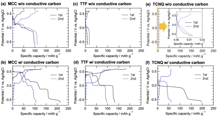
Charge/discharge performances were carried out using 1 M NaBr aqueous electrolyte (Figure 4a) and then compared to the performance using 46.5wt% of conductive carbon (AB) added cathode (Figure 4b). In addition, the charge/discharge performance was compared to the tests of the TTF cathode and TCNQ cathode, which were made of TTF or TCNQ with/without conductive carbon bound with PTFE (Figure 4c~4f). In Figure 4a and 4b, the MCC cathode with and without conductive carbon exhibited multi-plateaus attributed to TTF/TCNQ redox reactions as described later. The MCC cathode without conductive carbon exhibited a discharge capacity of around 100 mAh g–1 in the 1st and 2nd cycle. Although the cathode without conductive carbon has
a smaller capacity than the conductive carbon added cathode in the 1st cycle, the discharge capacity in the 2nd cycle is comparable to the conductive carbon added cathode. The reason why the conductive carbon added cathode has a larger capacity only in the 1st cycle is discussed later. Conversely, the TTF cathode and TCNQ cathode without conductive carbon have little capacity less than 20 mAh g–1 while the conductive carbon added cathodes showed over 100 mAh g–1 in
the initial discharge. This indicates that the use of insulating active materials would not work without conductive additives. From these results, the MCC cathode obtains enough electrical conductivity for charge/discharge with only simple mixing. In addition, EIS of the MCC cathode during 1st cycle was investigated as shown in Figure 5. According to the fittings, the solution resistance (Rsol) including electrical resistance in the electrode keeps constant value, and the charge
transfer resistance (Rct) affected by both ionic (Br– and Na+) conductivity and electrical
conductivity also keeps constant value except at the end of charge/discharge. These behaviors suggest that the electrode maintains enough electrical conductivity during charge/discharge.
13
Figure 4. 1st (black) and 2nd (blue) voltage curves. (a) MCC cathode without conductive carbon
and (b) with conductive carbon. (c) TTF cathode without conductive carbon and (d) with conductive carbon. (e) TCNQ cathode without conductive carbon and (f) with conductive carbon. Inset shows magnification.
Figure 5. (a) Electrochemical impedance spectra of the MCC cathode during 1st cycle. Dots and
lines are observed data and fitting curves, respectively. Overall spectra are shown in Figure S2. (b) Resistance fitted using the inserted equivalent circuit. Rsol: solution resistance; Rct:
charge-transfer resistance; CPE: constant phase element; W: Warburg element.
10 5 0 –Z'' / Ω 10 5 0 Z' / Ω (a) Before charge Half charged Full charged Half discharged Full discharged 1 2 4 6 8 10 2 4 6 8 100 2 R esi st an ce / Ω Before
charge chargedHalf chargedFull dischargedHalf dischargedFull W Rct Rsol CPE (b) Rsol Rct
14
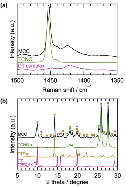
To confirm the expected electrical conductivity-relay mechanism during the charge/discharge process, analyses of both the pristine and redox state of the system was carried out. For the analysis of the pristine state, first, Raman spectra were measured to probe the valence state of the MCC cathode (Figure 6a). The Raman peaks of the TTF are much weaker than those of the TCNQ, such that that the peaks of the TTF could not be observed for the MCC cathode. So, a Raman peak of TCNQ was used to probe the state of charge-transfer between TTF and TCNQ in the MCC cathode. The MCC cathode had a strong peak at 1453 cm–1 and a broad weak peak at
around 1420 cm–1, which corresponds to the C=C stretching Ag mode of a pure TCNQ and
TTF-TCNQ CT complex, respectively.32 Because the charge state of TCNQ in the CT complex is –0.59,
both the state of the TCNQ0 (non-charge-transferred) and TCNQ0.59– (charge-transferred) exist in
the MCC cathode. However, the proportion of these states could not be quantified due to their scattering cross-sections being different. Secondly, the bulk crystal structure was investigated using XRD patterns (Figure 6b). In the pattern with the MCC cathode, sharp peaks attributed to TTF and TCNQ and the other broad peaks attributed to the CT complex were observed, suggesting that most of the bulk TTF and TCNQ remains, but partial CT complex formation occurs via the mixing process. The charge-transfer at the interface and the CT complex of TTF and TCNQ are similar in terms of the charge-transfer phenomenon and high electrical conductivity (TTF-TCNQ CT complex: 102~103 S cm–1 at room temperature,33 TTF-TCNQ charge-transfer at interface: 1~30
kΩ per square),23 excluding crystal structure and lattice energy. The high electrical conductivity
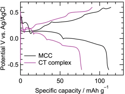
of the MCC cathode is probably derived from both types of charge-transfer. However, the pure CT complex cathode has poorer performance than the MCC cathode (Figure 7). Although the shape of the voltage curves of each cathode is similar, the CT complex cathode exhibited larger polarization than the MCC cathode. The CT complex cathode has a homogeneous structure and
15
the CT crystals inside are strongly packed with coulomb interaction in addition to π-stacking. This structure makes the insertion of carrier ions difficult to have larger over potentials (Figure 7). Note that an overshooting potential is observed especially at 0–10 mAh g–1, 0.1–0.2 V with CT complex
cathode. Such behavior has often been observed in cathode materials for lithium-ion battery,34 and
explained by the nucleation of new phase domains.35, 36 In the case here, the overshooting occurs
due to the large carrier ions of Br– and Na+ which cause large structure change to the cathode
16
Figure 6. (a) Raman spectra of the MCC cathode, CT complex, and TCNQ. (b) XRD patterns of
17
Figure 7. Comparison between the MCC cathode and the pure CT complex cathode in the 2nd
cycle.
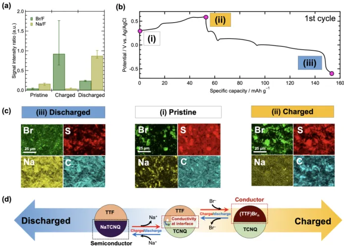
For the analysis of the electrodes during the charge/discharge process, SEM-EDX was performed to confirm the reversible insertion of Br– and Na+ into the MCC cathode. Figure 8a
presents quantitative amounts of Br and Na normalized using F in the PTFE binder. After the 1st charge, the amount of Br increased, suggesting Br– insertion to TTF crystals at the charge. After
discharge, the Br amount decreased and in turn, the Na amount increased, suggesting both Br–
desertion and Na+ insertion to TCNQ crystals at the discharge. The EDX mappings support the
quantitative analysis (Figure 8b and 8c). In the EDX mapping of the pristine state (i), a TTF-rich region and a TCNQ-rich region were distinguished by monitoring sulfur (TTF) and carbon (TCNQ) as described above, and similar distributions were also observed in the charged state (ii) and discharged state (iii). In the pristine state, weak signals of Br and Na are observed, localized to the sulfur-rich (TTF-rich) region and the carbon-rich (TCNQ-rich) region, respectively. This is because Br– and Na+ are stuck to the local charge of TTF0.59+ and TCNQ0.59–, respectively, at the
18
state, a Br signal appeared strongly in the sulfur-rich (TTF-rich) region and the localized Na signal disappeared. On the other hand, in the discharged state, a Na signal appeared in the carbon-rich (TCNQ-rich) region and a Br signal was weak and not localized. In the combination with quantitative analysis, these mappings strongly indicate that dual carrier ions were properly inserted into the active materials to form (TTF)Brx (x = n, 1, 2) after charge and Nay(TCNQ) (y = 1, 2) after
discharge. These results are consistent with the expected charge/discharge process of TTF and TCNQ, and proved that redox reactions of both TTF and TCNQ occurred.
Figure 8. Analyses of redox state of the MCC cathode with SEM-EDX. (a) Quantitative analyses
19
states of the MCC cathode. The values are the average of more than 5 points. (b) A voltage curve of the MCC cathode in the 1st cycle. (c) EDX mappings of the state at (i) (pristine), (ii) (charged), and (iii) (discharged). (d) Expected reaction scheme of the MCC cathode when charged and discharged.
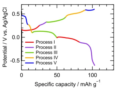
Each set of plateaus corresponding to redox pairs was confirmed using cyclic voltammetry (CV) and denoted as Process I ~ V as shown in Figure 9 (See Section S2 in Supporting Information for details). Then these Processes were assigned to equations 1~4, considering the reaction potential previously reported and the possible oxidation states. The reaction for Process II is still under investigation.
(Process I) TTF + nBr– ⇄ (TTF)Brn + ne– (1)
(Process III) NaTCNQ ⇄ TCNQ + Na+ + e– (2)
(Process IV) TTFBrn + (1 – n)Br– ⇄ (TTF)Br + (1 – n)e– (3)
(Process V) (TTF)Br + Br– ⇄ (TTF)Br2 + e– (4)
Based on the assigned redox reactions, the conductive radical salt, (TTF)Brn, was generated in the
charge of Process I, while the semiconducting radical salt, NaTCNQ, was generated in the discharge of Process III, indicating that the electrical conductivity of the charged/discharged electrode was supported by the organic salts formed. Surprisingly, for the entire electrode, further oxidation of the conductive (TTF)Brn appears to have proceeded (Process IV, V). This is
presumably attributed to there being a partial remnant of the conductive substances, such that charge-discharge cycles with stable capacity continued due to the residual electrical conductivity
20
of this remnant. Overall, the expected reaction occurred, and the expected conductive mechanisms worked during charge/discharge reactions.
Figure 9. Assignment of redox pairs (Process I ~ V) in the charge-discharge curve of the MCC
cathode in the 2nd cycle.
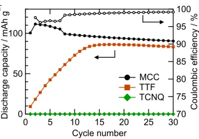
Next, the cyclability test was investigated as shown in Figure 10. The MCC cathode without conductive carbon exhibited the largest discharge capacity (112 mAh g–1) in the 2nd cycle
and a good capacity retention rate of 80.7% in the 30th cycle with the coulombic efficiency of >98% after 8th cycle. For comparison, the cyclability of the TTF cathode and TCNQ cathode were also investigated. While the TCNQ cathode showed low capacity during entire cycles, the TTF exhibited gradual capacity improvement over each cycle, going from 10 mAh g–1 to 86 mAh g–1
over 15 primary cycles. This can be explained through the gradual formation of conductive (TTF)Brn salt during early cycles, which then work as a conductive domain in the electrode.
Because the MCC cathode also contains TTF, the MCC cathode should also have the advantage -0.5 0.0 0.5 Po te nt ia l / V vs. Ag /Ag C l 100 50 0
Specific capacity / mAh g–1
Process I Process II Process III Process IV Process V
21
of the electrical conductivity of this salt. However, the amount of TTF in the MCC cathode is only about half that of the TTF cathode, and its cyclability is different from that of the TTF cathode, especially in its early cycles. Furthermore, the plateau of Process III remains even in the 30th cycle (Figure S4), which means the redox of TCNQ worked for long as well as the redox of TTF, and the reactions of MCC cathode in charge/discharge remain different from those of TTF cathode. Therefore, the continuous electrical conductivity of the MCC cathode cannot be explained only by the formation of (TTF)Brn. Hence, the electrical conductivity of (TTF)Brn in the MCC cathode
should only be partial, and the electrical conductivity of the MCC cathode is probably maintained by the combination of these radical salts such as (TTF)Brn and NaTCNQ and the charge-transfer
phenomenon. This result proves the electrical conductivity-relay concept. Next, a charge/discharge cycle of this MCC cathode without conductive carbon was performed in other aqueous electrolytes such as NaCl and LiCl (see Section S4 in Supporting Information for details). In these cases, the initial discharge capacity was comparable to that of the NaBr system due to the formation of conductive radical salts such as (TTF)Cln and LiTCNQ. The cyclability was clearly lower than in
NaBr electrolyte due to the higher solubility of the organic salts formed. Consequently, the low solubility, as well as electrical conductivity of organic salts formed during redox reactions is the crucial factor for high cyclability. Finally, the cyclabilities of the MCC cathode without/with conductive carbon were compared (Figure S6). In the cathode with conductive carbon, although the capacity of initial cycle was very high, cyclability was much worse than the electrode without conductive carbon. This is attributed to irreversible reactions occurring at the end of a charge (the plateau at 0.57 V) and discharge (the plateau at about –0.5 V) attributed to TTF2+Br–
2 formation
and Na+
2TCNQ2– formation, respectively.31 In the cathode without conductive carbon, these
22
process because (TTF)Brn turned to insulating (TTF)Br at the end of the charge, and the electrical
conductivity of the NaTCNQ was insufficient by itself to initiate further reduction during discharge. The EIS analyses in Figure 5 support increase in the electrode resistance at the end of charge/discharge. Because of this electrical conductivity-relay mechanism, reactions that lower the cyclability were prevented, and the cathode with superior electrical conductivity and cyclability was fabricated in an extremely easy way.
Figure 10. Capacity retention of the MCC cathode, TTF cathode, and TCNQ cathode without a
conductive additive. The coulombic efficiency of the MCC cathode is also shown. 100 50 0 D isch arg e ca pa ci ty / mAh g –1 30 25 20 15 10 5 0 Cycle number 100 95 90 85 80 75 70 C ou lo mb ic ef fici en cy / %
per active material
MCC TTF TCNQ
23 CONCLUSION
We demonstrated a novel electrical conductivity-relay system using TTF and TCNQ molecules as the active materials and aqueous sodium bromide as the electrolyte to make small organic molecules usable as electrode active materials without any conductive additive. This system recorded 112 mAh g–1 as its highest capacity, with a retention rate of 80.7% in its 30th
cycle. This system worked to impart electrical conductivity to the organic electrode materials both at the pristine state and the redox state with a combination of charge-transfer phenomenon and the formation of radical salts during the charge-discharge processes. Moreover, the Molecular Crystal Couples (MCC) electrode of this system shows the better charge/discharge performance than the pure charge-transfer complex electrode, suggesting that various pairs and mixing ratio of molecules even not forming charge-transfer complexes are applicable for organic conductive electrode materials. From these perspectives, this electrical conductivity-relay system using a MCC electrode expands the candidate to various small molecules.
24 ASSOCIATED CONTENT
Supporting Information
The Supporting Information is available free of charge on the ACS Publications website at DOI: 10.1021/xxxxx.
Electrical conductivity with four probe method, EIS spectra, assignment of electrochemical reactions, comparison of charge-discharge behaviors (PDF)
AUTHOR INFORMATION
Corresponding Author
*E-mail: [email protected].
ORCID: 0000-0001-6705-9515 Notes
The authors declare no competing financial interest.
ACKNOWLEDGMENTS
We thank Mr. Hideyuki Magara for his support about SEM-EDX measurement. This work was supported in part by "Dynamic Alliance for Open Innovation Bridging Human, Environment and Materials" from the Ministry of Education, Culture, Sports, Science and Technology of Japan (MEXT) and JSPS KAKENHI Grant Number JP19K15668. M. Yamashita thanks the support by the 111 project (B18030) from China.
25 REFERENCES
(1) Liang, Y.; Tao, Z.; Chen, J. Organic electrode materials for rechargeable lithium batteries. Adv.
Energy Mater. 2012, 2 (7), 742-769.
(2) Xie, J.; Zhang, Q. Recent progress in rechargeable lithium batteries with organic materials as promising electrodes. J. Mater. Chem. A 2016, 4 (19), 7091-7106.
(3) Zhao, Q.; Lu, Y.; Chen, J. Advanced organic electrode materials for rechargeable sodium-ion batteries. Adv. Energy Mater. 2017, 7 (8), 1601792.
(4) Lu, Y.; Chen, J. Prospects of organic electrode materials for practical lithium batteries. Nat.
Rev. Chem. 2020, 4, 127-142.
(5) Shea, J.; Luo, C. Organic Electrode Materials for Metal Ion Batteries. ACS Appl. Mater.
Interfaces 2020, 12 (5), 5361-5380.
(6) Kundu, D.; Oberholzer, P.; Glaros, C.; Bouzid, A.; Tervoort, E.; Pasquarello, A.; Niederberger, M. Organic cathode for aqueous Zn-ion batteries: taming a unique phase evolution toward stable electrochemical cycling. Chem. Mater. 2018, 30 (11), 3874-3881.
(7) Bai, Y.; Fu, W.; Chen, W.; Chen, Z.; Pan, X.; Lv, X.; Wu, J.; Pan, X. Perylenetetracarboxylic diimide as a high-rate anode for potassium-ion batteries. J. Mater. Chem. A 2019, 7 (42), 24454-24461.
(8) Tomai, T.; Mitani, S.; Komatsu, D.; Kawaguchi, Y.; Honma, I. Metal-free aqueous redox capacitor via proton rocking-chair system in an organic-based couple. Sci. Rep. 2014, 4, 3591. (9) Liang, Y.; Jing, Y.; Gheytani, S.; Lee, K.-Y.; Liu, P.; Facchetti, A.; Yao, Y. Universal quinone electrodes for long cycle life aqueous rechargeable batteries. Nat. Mater. 2017, 16 (8), 841-848. (10) Emanuelsson, R.; Sterby, M.; Strømme, M.; Sjödin, M. An all-organic proton battery. J. Am.
Chem. Soc. 2017, 139 (13), 4828-4834.
(11) Perticarari, S.; Sayed-Ahmad-Baraza, Y.; Ewels, C.; Moreau, P.; Guyomard, D.; Poizot, P.; Odobel, F.; Gaubicher, J. Dual Anion–Cation Reversible Insertion in a Bipyridinium–Diamide Triad as the Negative Electrode for Aqueous Batteries. Adv. Energy Mater. 2018, 8 (8), 1701988. (12) Mike, J. F.; Lutkenhaus, J. L. Recent advances in conjugated polymer energy storage. J.
Polym. Sci. B Polym. Phys. 2013, 51 (7), 468-480.
(13) Xie, J.; Gu, P.; Zhang, Q. Nanostructured conjugated polymers: toward high-performance organic electrodes for rechargeable batteries. ACS Energy Lett. 2017, 2 (9), 1985-1996.
26
(14) Mukherjee, B.; Mukherjee, M. High Performance Organic Thin Film Transistors with Solution Processed TTF-TCNQ Charge Transfer Salt as Electrodes. Langmuir 2011, 27 (17), 11246-11250.
(15) Marzouk, S. A.; Cosofret, V. V.; Buck, R. P.; Yang, H.; Cascio, W. E.; Hassan, S. S. A conducting salt-based amperometric biosensor for measurement of extracellular lactate accumulation in ischemic myocardium. Anal. Chem. 1997, 69 (14), 2646-2652.
(16) Khan, G. F.; Ohwa, M.; Wernet, W. Design of a stable charge transfer complex electrode for a third-generation amperometric glucose sensor. Anal. Chem. 1996, 68 (17), 2939-2945.
(17) Cano, M.; Palenzuela, B.; Rodríguez-Amaro, R. A TTF–TCNQ Electrode as a Voltammetric Analogue of an Ion-Selective Electrode. Electroanalysis: An International Journal Devoted to
Fundamental and Practical Aspects of Electroanalysis 2006, 18 (11), 1068-1074.
(18) Wooster, T. J.; Bond, A. M.; Honeychurch, M. J. An analogy of an ion-selective electrode sensor based on the voltammetry of microcrystals of tetracyanoquinodimethane or tetrathiafulvalene adhered to an electrode surface. Anal. Chem. 2003, 75 (3), 586-592.
(19) Lee, S.; Hong, J.; Jung, S.-K.; Ku, K.; Kwon, G.; Seong, W. M.; Kim, H.; Yoon, G.; Kang, I.; Hong, K. Charge-transfer complexes for high-power organic rechargeable batteries. Energy
Stor. Mater. 2019, 20, 462-469.
(20) Ferraris, J.; Cowan, D.; Walatka, V.; Perlstein, J. Electron transfer in a new highly conducting donor-acceptor complex. J. Am. Chem. Soc. 1973, 95 (3), 948-949.
(21) Goto, H.; Fujinawa, T.; Asahi, H.; Inabe, T.; Ogata, H.; Miyajima, S.; Maruyama, Y. Crystal structures and physical properties of 1, 6-diaminopyrene-p-chloranil (DAP-CHL) charge-transfer complex. Two polymorphs and their unusual electrical properties. Bull. Chem. Soc. Jpn. 1996, 69 (1), 85-93.
(22) Jacobsen, C. S.; Mortensen, K.; Andersen, J. R.; Bechgaard, K. Transport properties of some derivatives of tetrathiafulvalene-tetracyano-p-quinodimethane (TTF-TCNQ). Phys. Rev. B 1978,
18 (2), 905.
(23) Alves, H.; Molinari, A. S.; Xie, H.; Morpurgo, A. F. Metallic conduction at organic charge-transfer interfaces. Nat. Mater. 2008, 7 (7), 574-580.
27
(25) Adeel, S. M.; Martin, L. L.; Bond, A. M. Redox-induced solid-solid state transformation of tetrathiafulvalene (TTF) microcrystals into mixed-valence and π-dimers in the presence of nitrate anions. J. Solid State Electrochem. 2014, 18 (12), 3287-3298.
(26) Bond, A. M.; Fiedler, D. A. In situ electrochemical and electron spin resonance studies of microcrystals mechanically attached to an electrode surface. J. Electrochem. Soc. 1997, 144 (5), 1566-1574.
(27) Wooster, T. J.; Bond, A. M. Ion selectivity obtained under voltammetric conditions when a TCNQ chemically modified electrode is presented with aqueous solutions containing tetraalkylammonium cations. Analyst 2003, 128 (11), 1386-1390.
(28) Shaw, S. J.; Marken, F.; Bond, A. M. Detection of new features associated with the oxidation of microcrystalline tetrathiafulvalene attached to gold electrodes by the simultaneous application of electrochemical and quartz crystal microbalance techniques. Electroanalysis 1996, 8 (8-9), 732-741.
(29) Wooster, T. J.; Bond, A. M.; Honeychurch, M. J. Resistance transitions detected by analysis of the voltammetry of tetrathiafulvalene microparticles adhered to electrode surfaces under conditions of dynamic resistance compensation. Electrochem. Commun. 2001, 3 (12), 746-752. (30) Scott, B.; La Placa, S.; Torrance, J.; Silverman, B.; Welber, B. The crystal chemistry of organic metals. Composition, structure, and stability in the tetrathiafulvalinium-halide systems. J.
Am. Chem. Soc. 1977, 99 (20), 6631-6639.
(31) Bond, A.; Symons, P. The relationship between the electrochemistry and the crystallography of microcrystals. The case of TCNQ (7, 7, 8, 8-tetracyanoquinodimethane). Analyst 1998, 123 (10), 1891-1904.
(32) Takahashi, Y.; Hayakawa, K.; Naito, T.; Inabe, T. What Happens at the Interface between TTF and TCNQ Crystals (TTF= Tetrathiafulvalene and TCNQ= 7, 7, 8, 8-Tetracyanoquinodimethane)? J. Phys. Chem. C 2012, 116 (1), 700-703.
(33) Thomas, G.; Schafer, D.; Wudl, F.; Horn, P.; Rimai, D.; Cook, J.; Glocker, D.; Skove, M.; Chu, C.; Groff, R. Electrical conductivity of tetrathiafulvalenium-tetracyanoquinodimethanide (TTF-TCNQ). Phys. Rev. B 1976, 13 (11), 5105.
(34) Kobayashi, H.; Hibino, M.; Ogasawara, Y.; Yamaguchi, K.; Kudo, T.; Okuoka, S.-i.; Yonehara, K.; Ono, H.; Sumida, Y.; Oshima, M. Improved performance of Co-doped Li2O
28
cathodes for lithium-peroxide batteries using LiCoO2 as a dopant source. J. Power Sources 2016,
306, 567-572.
(35) Sasaki, T.; Ukyo, Y.; Novák, P. Memory effect in a lithium-ion battery. Nat. Mater. 2013, 12 (6), 569-575.
(36) Netz, A.; Huggins, R. A. Amorphous silicon formed in situ as negative electrode reactant in lithium cells. Solid State Ionics 2004, 175 (1-4), 215-219.
29 ABSTRACT GRAPHIC