3D MODELING OF OUTDOOR SCENES FROM OMNIDIRECTIONAL RANGE AND COLOR IMAGES
7
0
0
全文
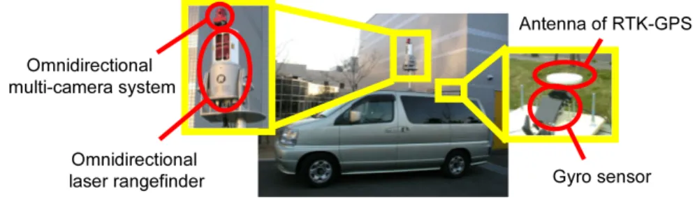
(2) 2 Antenna of RTK-GPS Omnidirectional multi-camera system. Omnidirectional laser rangefinder. Figure 1.. Gyro sensor. Sensor system mounted on a car.. ages. Section 3 explains the 3D modeling method which integrates range and color images obtained at multiple positions. In Section 4, experimental results with the proposed method are described. Finally, Section 5 gives summary and future work.. 2.. Sensor System. 2.1. Data Acquisition. Fig. 1 illustrates the sensor system mounted on a vehicle. The system equips the omnidirectional laser rangefinder (Riegl, LMS-Z360), omnidirectional camera (Point Grey Research, Ladybug), and RTK-GPS. Fig. 2 shows an acquired omnidirectional range image in which the distance from the rangefinder is coded in intensity. Fig. 3 shows a generated omnidirectional color image from images acquired by OMS. Note that the maximum measurable range of rangefinder is about 200m and its measurement accuracy is within 12mm. Ladybug has radially located six camera units in a camera block and their positions and orientations are fixed. Since each camera can acquire a 76821024 image, the Ladybug can acquire high-resolution omnidirectional color images which covers more than 75% of full spherical view. The Ladybug is calibrated geometrically and photometrically in advance[8]. RTK-GPS and gyro sensor are used to measure the position and orientation of the sensor system. The measurement accuracy is about 3cm. The orientation of the sensor system is measured by the gyro sensor whose measurement accuracy is within 0.5 deg. Usually, yaw value measured by gyro sensor usually includes an accumulative error. In this paper, to avoid the accumulative error, the measurement yaw value of gyro sensor is corrected by interlocking with RTK-GPS.. 2.2. Alignment of Coordinate Systems. There are four coordinate systems in the sensor system; the rangefinder, the OMS, the RTK-GPS, and the gyro sensor coordinate systems. Geometrical.
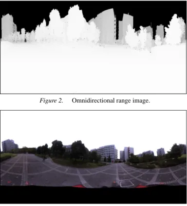
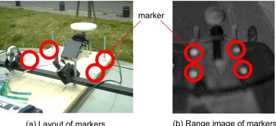
(3) 3. Figure 2.. Omnidirectional range image.. Figure 3.. Omnidirectional color image.. relationship among the coordinate systems is fixed, and these coordinate systems are registered to RTK-GPS(global) coordinate system as shown in Fig. 4. The method for estimating the transformation matrixes which represent the relationship among the coordinate systems is described below.. (a) Matrix between OMS and rangefinder coordinate systems. By giving the corresponding points of range and color images, the transformation matrix can be estimated by [8]. (b) Matrix between rangefinder and gyro sensor coordinate systems. The transformation matrix can be estimated by measuring more than three markers whose positions in the gyro sensor coordinate system are known. The markers are placed at positions which can be measured by the rangefinder as shown in Fig. 5(a). The positions of markers in rangefinder coordinate system are estimated by the range data as shown in Fig. 5(b). (c) Matrix between gyro sensor and global coordinate systems. Z-axis of the gyro sensor coordinate system can correspond with Alt-axis of the global coordinate system when the gyro sensor is powered up. The transformation matrix usually consists of rotation and translation components. The translation.
(4) 4 zL. yL xL zr. OMS. (a) Alt.. rangefinder. yr. RTK-GPS. xr. (b) xg. Lon.. gyro sensor. (c). Lat. global coordinate system. Figure 4.. yg zg. Relationship among the coordinate systems of the sensors.. marker. (a) Layout of markers Figure 5.. (b) Range image of markers. Alignment of rangefinder and gyro sensor coordinate systems.. component of the transformation matrix can be acquired by RTK-GPS. On the other hand, the rotation component can be estimated by the gyro sensor. However, only offset of yaw direction in gyro sensor coordinate system and yaw direction in global coordinate system is unknown. The x-axis of gyro sensor coordinate system is aligned with Lat-axis of global coordinate system by measuring a same point in the real scene with rangefinder from two different points.. 3.. 3D Modeling of Outdoor Environmets. 3.1. Registration of Multiple Range Images. In order to register the multiple range images, the ICP algorithm is used[9, 10]. The position and orientation of the rangefinder are acquired by the RTKGPS and the gyro sensor, respectively. The error of orientation value influences.
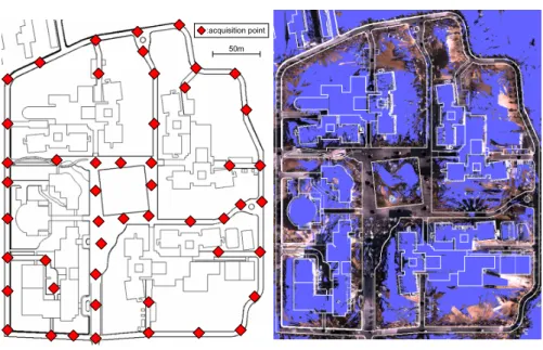
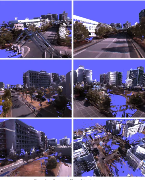
(5) 5 parts far from the rangefinder, therefore the acquired position by RTK-GPS is used as position of range data, though the acquired orientation of gyro sensor is used as the initial value of orientation of range data. In the conventional ICP algorithm, the distance between points in paired range data is defined as an error, and the transformation matrix is calculated so that the error is minimized. The present rangefinder measures the distance by rotating the laser scan, thus the spatial density of data points depends on the distance; that is, close objects are measured densely and far objects are measured sparsely. This causes a problem in registering range data obtained at different positions. In order to overcome this problem, we define an error by computing the distance between a point in one data set and a plane determined by adjacent points in the other data set[11].. 3.2. Texture-mapping of Color Images on 3D Shape. The 3D shape obtained in the previous section is texture-mapped by omnidirectional color images. Each triangular patch on the 3D shape is colored by the texture from the image which gives the highest resolution. However this strategy fails when an occlusion occurs. The occlusion is detected when the whole 3D shape intersects with a triangular pyramid determined by triangular patch vertexes and the projection center of camera. In such a case, the second highest resolution image is selected.. 4.. Experiments. We have carried out experiments of reconstructing our campus. In experiments, the range and color images are acquired at 50 points in our campus (about 250m2 300m). Fig. 6 shows the acquisition points of data in our campus. The sensor coordinate systems are aligned in advance with the proposed method described in Section 2.2. The resolution of each omnidirectional range image is 9042450. The number of polygons of the generated 3D model is 2,930,462. Fig. 7 illustrates a 2D CAD data of our campus overlaid with the generated model. We confirm that the generated model has no large distortion. Examples of rendering the generated model are shown in Fig. 8.. 5.. Conclusion. This paper has proposed a 3D modeling method which is based on integrating omnidirectional range and color images for wide area outdoor environments. In experiments, a 3D model is actually generated from omnidirectional range and color images acquired 50 points in our campus. We can move viewpoint and look around the model freely. However, the sense of incongruity is observed in the generated model, when different images are selected in neighboring polygons. Such an effect is mainly caused by the varying illumination.
(6) 6 :acquisition point 50m. Figure 6.. Range data acquisition points.. Figure 7. 2D CAD data overlaid on generated 3D model. conditions during the measurement of whole area. This problem in generating textured 3D model should further be investigated.. References [1] T. Sato, M. Kanbara, N. Yokoya and H. Takemura: “Dense 3-D Reconstruction of an Outdoor Scene by Hundreds-baseline Stereo Using a Hand-held Video Camera,” International Jour. of Computer Vision,Vol. 47, No. 1-3, pp. 119–129, 2002. [2] C. Tomasi and T. Kanade: “Shape and Motion from Image Streams under Orthography: A Factorization Method,” International Jour. of Computer Vision, Vol. 9, No. 2, pp. 137–154, 1992. [3] M. Okutomi and T. Kanade: “A Multiple-baseline Stereo,” IEEE Trans. on Pattern Analysis and Machine Intelligence, Vol. 15, No. 4, pp. 353–363, 1993. [4] S. F. El-Hakim, C. Brenner and G. Roth: “A Multi-sensor Approach to Creating Accurate Virtual Environments,” Jour. of Photogrammetry & Remote Sensing, Vol. 53, pp. 379–391, 1998. [5] H. Zhao and R. Shibasaki: “Reconstruction of Textured Urban 3D Model by Fusing Ground-Based Laser Range and CCD Images,” IEICE Trans. Inf. & Syst., Vol. E-83-D, No. 7, pp. 1429–1440, 2000. [6] P. K. Allen, A. Troccoli, B. Smith, S, Murray, I. Stamos and M. Leordeanu: “New Methods for Digital Modeling of Historic Sites,” IEEE Computer Graphics and Applications, Vol. 23, pp. 32–41, 2003. [7] C. Fru h and A. Zakhor: “Constructing 3D City Models by Merging Aerial and Ground Views,” IEEE Computer Graphics and Applications, Vol. 23, pp. 52–61, 2003..
(7) 7. Figure 8.. Generated 3D model with the texture.. [8] S. Ikeda, T. Sato, and N. Yokoya: “Panoramic Movie Generation Using an Omnidirectional Multi-camera System for Telepresence,” Proc. 13th Scandinavian Conf. on Image Analysis, pp. 1074–1081, 2003. [9] P. J. Besl and N. D. McKay: “A Method for Registration of 3-D Shapes,” IEEE Trans. on Pattern Analysis and Machine Intelligence, Vol. 14 No. 2, pp. 239–256, 1992. [10] T. Oishi, R. Sagawa, A. Nakazawa, R. Kurazume and K. Ikeuchi: “Parallel Alignment of a Large Number of Range Images,” Proc. International Conf. on 3D Digital Imaging and Modeling, pp. 195–202, 2003. [11] K. Pulli: “Multiview Registration for Large Data Sets,” Proc. International Conf. on 3D Digital Imaging and Modelling, pp. 160–168, 1999..
(8)
図
+2
関連したドキュメント
Standard domino tableaux have already been considered by many authors [33], [6], [34], [8], [1], but, to the best of our knowledge, the expression of the
We generalized Definition 5 of close-to-convex univalent functions so that the new class CC) includes p-valent functions.. close-to-convex) and hence any theorem about
We generalized Definition 5 of close-to-convex univalent functions so that the new class CC) includes p-valent functions.. close-to-convex) and hence any theorem about
Applications of msets in Logic Programming languages is found to over- come “computational inefficiency” inherent in otherwise situation, especially in solving a sweep of
Shi, “The essential norm of a composition operator on the Bloch space in polydiscs,” Chinese Journal of Contemporary Mathematics, vol. Chen, “Weighted composition operators from Fp,
[2])) and will not be repeated here. As had been mentioned there, the only feasible way in which the problem of a system of charged particles and, in particular, of ionic solutions
Using variational techniques we prove an eigenvalue theorem for a stationary p(x)-Kirchhoff problem, and provide an estimate for the range of such eigenvalues1. We employ a
Khovanov associated to each local move on a link diagram a homomorphism between the homology groups of its source and target diagrams.. In this section we describe how this
