VGクラスタにおけるパラレルポートを利用した低コストハードウェアバリアの性能評価
6
0
0
全文
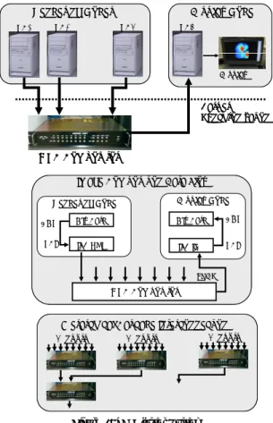
(2) Currently, both the complete VG Clusters (MPC VGCluster) and the image composition device (MPC Compositor) are available on the market [4]. The MPC Compositor shows high image composition performance. However, this device has adopted the synchronous image composition approach which requires barrier synchronization before each image composition step. Because this system does not possess any hardware synchronization mechanism, it is required to use an external synchronization method. The simplest solution is to use MPI_Barrier [5], the well-known software barrier used in the distributed memory programming approach. The performance of the MPI_Barrier and other software based barrier synchronization mechanisms is highly dependent on the network condition, such as bandwidth and traffic. In this report, we present a simple hardware barrier synchronization device which utilizes parallel ports of the PC Cluster nodes. We have evaluated this device on our nine-node VG Cluster and verified a substantial improvement especially when using Fast-Ethernet and also when the network is congested. This is also expected to be especially useful in larger VG Cluster systems where the software barrier synchronization performance is affected more. 2. VG Cluster System VG Cluster is a result of the joint research project started by the National Institute of Advanced Industrial Science (AIST) and Mitsubishi Precision Co. Ltd. (MPC) with the aim of developing a cost-effective, high performance visualization system. The main distinction from other solutions is the original image composition device. Currently, this device is also being sold separately enabling users to build their own VG Cluster based on their budget. This device has high scalability which enables the building of large VG Cluster systems of up to 512 computing nodes through the use of hierarchical cascade interconnection. The image composition hardware kit is composed of the MPC Compositor itself,. Rendering Nodes PC1. PC2. Display Node PC8. PC9. . . . Display. Barrier Synchronization. MPC Compositor Image Composition Data Flow Display Node. Rendering Node AGP. Gfx Card. Gfx Card. AGP. PCI. IFB OUT. IFB IN. PCI. LVDS. MPC Compositor. Hierarchical Cascade Interconnection 8 inputs. 8 inputs. 8 inputs. . . .. . . .. Figure 1: VG Cluster System. PCI-based Interface cards called IFB IN/OUT, and Low Voltage Differential Signaling (LVDS) cables. Currently, there is only one model of MPC Compositor available on the market and it has one output and eight input ports. These ports are connected through the LVDS cables to the IFB cards (IFB IN / OUT) on the PC side. The current device driver allows only one IFB card per PC, thus the minimum configuration VG Cluster will constitute nine nodes. Figure 1 shows the simplified diagram of the VG Cluster system. The IFB cards have 4MB of memory to store the 24-bit RGBA images to be composited, thus enabling a maximum image size of 2048x2048 to be composited in a single step. However, MPC Compositor does not possess a buffer for storing the images to be composited, and synchronous data transfer is required. Because this system does not possess any hardware synchronization mechanism, the global synchronization is handled by the application. A natural solution is to use functions available on parallel programming libraries such as MPI_Barrier.. −26− -2-.
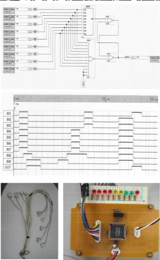
(3) 3. Parallel-port based Hardware Barrier Barrier synchronization is a collective operation commonly used in parallel and distributed applications. Most of the parallel and distributed programming libraries have the barrier operation included as part of their specifications. The MPI, the de facto standard message passing library, has the function MPI_Barrier function for performing barrier synchronization. During the barrier synchronization, all processes involved should wait until completion before proceeding to the next step. Thus, it becomes highly important to minimize the amount of time spent waiting for the barrier synchronization. MPI_Barrier as well as other software based barrier operations, utilizes the interconnection network making the performance dependent on the network condition and the quantity of nodes involved. In order to overcome this problem, several hardware solutions have been proposed so far. One of the most interesting solutions for. COTS PC Cluster is the TTL_PAPERS [6], which is a low-cost solution designed to perform a set of aggregate operations. Our hardware device is similar to this solution, however we have only implemented the static barrier synchronization mechanism. Mainboards of PCs usually have several on-board I/O ports which are not used in the cluster. Among these ports, the parallel port has been widely utilized in assisting the synchronization process. For instance, we can point out the use in aggregate communication [6], clock synchronization [7], performance measurement [8], and software genlock [9]. Its popularity is in part due to the simplicity of hardware architecture and its easy programmability. Depending on the operating system being used, this port can be accessed directly without the use of a device driver. For instance, Linux offers the ioperm system call which enables user level access to I/O ports. When making full use of the MPC Compositor, all nodes should be synchronized before each image composition step. In this case, a static barrier synchronization which involves all nodes is sufficient. In this first trial, we have designed and implemented only a static barrier synchronization mechanism using COTS components. All the. Figure 3: VG Cluster. Figure 2: Parallel-port-based Hardware Barrier. −27− -3-.
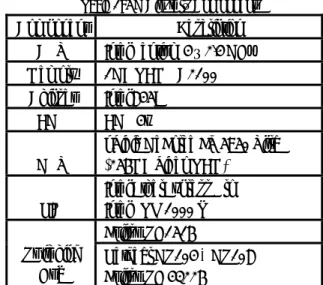
(4) utilized components were bought from ordinary electronic components store. Although we have utilized FPGA (32 macro-cell ALTERA PM7032), it can easily be replaced by traditional logic ICs, thus does not require any highly specialized components or tools for assembly. The implemented barrier synchronization logic is shown in Figure 2. Although parallel port supports eight-bit bi-directional communication, we have only used one bit for both the output and input. Regarding input signal, it was possible to use hardware interruption (IRQ). However, considering that processes should wait until other nodes reach the barrier point, we adopted the use of poling which makes the software implementation simpler. As this is not dependent on the hardware, we can use other ports on the PC. This system shows high scalability and it is theoretically possible to support even the full configuration 512-node VG Cluster. Although we have implemented this prototype utilizing different components to the TTL_PAPERS, they have similar working behavior. Instead of using the simplest solution, hardwired AND with external reset mechanism, we adopted the use of an additional logic circuit to provide barrier signal in both high and low levels as we can see in Figure 2. The synchronization latency of this device can be described as: TTotal = TInternal + ( 3 x TGates ). For the utilized FPGA, TInternal corresponds to approximately 11.7 ns. and TGates corresponds to 3.3 ns. Thus the total latency is in the order of an insignificant 21.6 ns.. Table 1: VG Cluster’s Components. Component CPU. Description Intel Pentium 4 – 2.4 GHz. Memory. 1GB RAM PC2100. Chipset. Intel 845E. AGP. AGP 4x. GPU. nVidia GeForce FX 5950 Ultra (256MB Video RAM). NIC. Intel EtherExpress Pro Intel PRO 1000 T Fujitsu SH1516. Switching Hub. Netgear GS104 + GS108 Fujitsu SH 43226. provide faster communication. Eight of the nodes are designed to act as hardware-assisted rendering nodes and one front-end node for display and user interaction. The main hardware components of each node are shown in Table 1. We have used SCore 5.2.0 as the cluster management software, which makes it possible to utilize the lightweight PM/Ethernet communication protocol. Each node runs the RedHat Linux 7.3, kernel 2.4.18-3SCore, and we have used C++ with MPI library (MPICH/PM) as well as Image Compositor library (MPC Compositor API) for building the parallel graphics applications. Assuming that parallel rendering applications have generated 24-bit RGBA images at each rendering node in high frame rate, the image composition process starts by transferring these image data to the IFB OUT cards to be. 4. Performance Evaluation. Fujitsu SH43226. Fujitsu SH1516. We have used a minimum configuration VG Cluster for the performance evaluation. This VG Cluster was built mainly for investigating its potential in assisting local collaborative visualization [10] and remote visualization of large volume data by using volume data streaming technique [11]. Our VG Cluster consists of nine COTS PCs (Fujitsu w600) interconnected by Fast Ethernet network. An additional Gigabit Ethernet interconnection network has been added to. −28− -4-. Netgear GS104 + GS108. . PC1. PC2. .. . PC8. Figure 4: Network Interconnection. PC9.
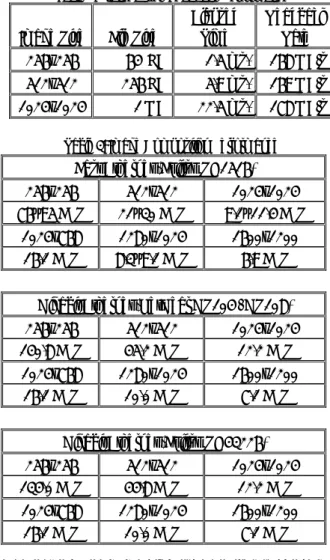
(5) Table 2: Framebuffer Readback Performance. Image Size. File Size. Elapsed Time. Readback Rate. 256x256. 64 KB. 1.5 ms.. 168 MB/s. 512x512. 256 KB. 5.9 ms.. 169 MB/s. 1 MB. 22.5 ms.. 178 MB/s. 1024x1024. Table 3: Image Composition Performance. Fast Ethernet (Fujitsu SH1516) 256x256 76~95 FPS. 512x512 21~30 FPS. 1024x1024 9.1~11.4 FPS. 1024x768 16.1 FPS. 1280x1024 8.3~9.1 FPS. 1600x1200 6.9 FPS. Gigabit Ethernet (NetGear GS104 / GS108) 256x256 140.8 FPS. 512x512 45.2 FPS. 1024x1024 12.2 FPS. 1024x768 16.1 FPS. 1280x1024 10.0 FPS. 1600x1200 7.1 FPS. Gigabit Ethernet (Fujitsu SH43226) 256x256 134.0 FPS. 512x512 44.8 FPS. 1024x1024 12.2 FPS. 1024x768 16.1 FPS. 1280x1024 10.0 FPS. 1600x1200 7.1 FPS. composited. This is called framebuffer readback. In order to evaluate this framebuffer readback performance, we utilized the OpenGL glReadPixels function and three RGBA images of the sizes usually used for performance evaluation of graphics applications. The corresponding framebuffer readback overhead is shown in Table 2. For subsequent evaluation, we have added three more RGBA images simulating the full resolution of commonly used displays. After barrier synchronization, the image data is sent to the MPC Compositor and the resulting image is stored on the IFB IN card at the display node. This resulting image is then transferred to the graphics card framebuffer for subsequent display. We utilized the OpenGL glDrawPixels function to execute this data transfer. In order to verify the maximum image composition performance, we have simulated a continuous image composition process by executing the. aforementioned steps in a loop. To verify how interconnection network affects the overall performance, we evaluated this image composition process using different network configurations. The obtained results are shown in Table 3. This result confirms that the overall performance is dependent on the network configuration. We have evaluated the MPI_Barrier call in order to verify the overhead caused by each call to this function. In order to avoid external factors in this measurement, we disconnected the cable to the external network. The obtained results are shown in Table 4 and we have found a drastic difference between Fast and Gigabit Ethernet. In an artificially congested network created by simulating high traffic rate, the synchronization times have exceeded 10 ms and 0.5 ms respectively on Fast and Gigabit Ethernet network confirming the performance dependency on the network conditions. In order to verify the overhead of our proposed hardware barrier, we have measured the synchronization latency. The average time required to write to (OUT) and read from (IN) parallel port at each node is shown in Table 5. Even when including the delay time of the FPGA circuit we can obtain synchronization in less than three microseconds.. −29− -5-. Table 4: MPI_Barrier Performance. Network. Time. Fast Ethernet. 3.7 ms.. Gigabit Ethernet. 0.1 ms.. Table 5: Latency of Parallel Port. Node. OUT. IN. Total. PC1. 1.24 us.. 1.36 us.. 2.76 us.. PC2. 1.24 us.. 1.37 us.. 2.61 us.. PC3. 1.26 us.. 1.36 us.. 2.61 us.. PC4. 1.25 us.. 1.35 us.. 2.62 us.. PC5. 1.26 us.. 1.36 us.. 2.61 us.. PC6. 1.25 us.. 1.36 us.. 2.62 us.. PC7. 1.24 us.. 1.36 us.. 2.61 us.. PC8. 1.24 us.. 1.38 us.. 2.60 us.. PC9. 1.24 us.. 1.42 us.. 2.63 us..
(6) References. Table 6: Image Composition Performance. Fast Ethernet + Hardware Barrier 256x256 144.9 FPS. 512x512 45.8 FPS. 1024x1024 12.3 FPS. 1024x768 16.5 FPS. 1280x1024 10.0 FPS. 1600x1200 7.1 FPS. After setting the hardware synchronization device on the VG Cluster, we have executed the same performance evaluation for the purpose of comparison. The obtained results are shown in Table 6. When compared to Table 3 we can verify the greatest improvement when using Fast Ethernet. Even slight improvement is also noticeable in the case of Gigabit Ethernet. More significant gains are expected when using a larger VG Cluster or in a congested network. This situation can occur when utilizing remote rendering or distributed rendering approach. In addition, considering that VG Cluster can be used for executing both numerical simulations and visualization on the same system, it is expected that this device will contribute to reducing the barrier overhead during numerical simulations.. 5. Conclusion We presented a simple yet powerful hardware device for assisting barrier synchronization on VG Clusters built using COTS PCs. This device shows high scalability and has proven especially useful in VG Clusters built using a low-speed network or those connected to congested networks. Moreover, the use of FPGA brings us flexibility for further enhancements. As future works, we are planning to further utilize the FPGA by adding functions such as dynamic barrier synchronization [12]. This function will bring more flexibility to the parallel and distributed applications. In addition, we are also considering the implementation of software genlock [9] for enabling the use of an active stereoscopic display system to enhance the VG Cluster’s use.. [1] R.A. Earnshaw, N. Wiseman, “An Introductory Guide to Scientific Visualization,” Springer-Verlag, Berlin, (1992) [2] K-L. Ma, E.B. Lum, S. Muraki, “Recent Advances in Hardware-Accelerated Volume Rendering,” Computer & Graphics, Vol. 27, pp. 725-734, (2003) [3] S. Muraki, M. Ogata, K-L. Ma, K. Koshizuka, K. Kajihara, X. Liu, Y. Nagano, K. Shimokawa, “Next-Generation Visual Supercomputing using PC Clusters with Volume Graphics Hardware Devices,” In Proc. SC 2001, CD-ROM, (2001) [4] http://www.mpcnet.co.jp/prodct/vg/index_vg.html [5] http://www-unix.mcs.anl.gov/mpi/ [6] H. G. Dietz and R. Hoare and T. Mattox, “A Fine-Grain Parallel Architecture Based on Barrier Synchronization,” In Proc. ICPP’96, pp. 247-250, (1996) [7] J. Nonaka, G. H. Pfitscher, K. Onishi, H. Nakano, “Low-Cost Hybrid Internal Clock Synchronization Mechanism for COTS PC Cluster,” In Proc. Euro-Par 2002, pp. 121-124 (2002) [8] M. Haridasan, G. H. Pfitscher, “Use of the Parallel Port to Measure MPI Intertask Communication Costs in COTS PC Cluster,” In Proc. IPDPS 2003, (2003) [9] J. Allard, V. Gouranton, G. Lamarque, E. Melin, B. Raffin, “Softgenlock: Active Stereo and Genlock for PC Cluster,” In Proc. Joint IPT/EGVE'03 Workshop, (2003) [10] J. Nonaka, N. Kukimoto, M. Watanabe, Y. Ebara, T. Matsuzawa, M. Kanazawa, K. Koyamada, “Remote Visualization Framework for Promoting Cooperative Visualization,” In Proc. AFI/TFI 2004, pp. 165-170 (2004) [11] Y. Ebara, Y. Watashiba, K. Koyamada, K. Sakai, A. Doi, “Remote Visualization Using Resource Monitoring Technique for Volume Rendering of Large Datasets,” In Proc. IEEE SAINT 2004, pp. 309-312 (2004) [12] T. A. Johnson, R.R. Hoare, “Cyclical Cascade Chains: A Dynamic Barrier Synchronization Mechanism for Multiprocessor Systems,” In Proc. IPDPS 2001, pp. 2061-2068 (2001). −30− - 6 - End.
(7)
図
+2
関連したドキュメント
Recent advances in combinatorial representation theory RIMS, Kyoto University... Quantum
If Φ is a finite root system, and if we take H 0 to be the category of representations of an alternating quiver corresponding to Φ , then our generalized cluster complex is the
We construct critical percolation clusters on the diamond hierarchical lattice and show that the scaling limit is a graph directed random recursive fractal.. A Dirichlet form can
In this paper we develop an elementary formula for a family of elements {˜ x[a]} a∈ Z n of the upper cluster algebra for any fixed initial seed Σ.. This family of elements
The layout produced by the VDCB algorithm is more evenly distributed according to the CP model, and is more similar to the original layout according to the similarity measures
Nakanishi, “Exact WKB analysis and cluster algebras II: simple poles, orbifold points, and generalized cluster algebras”, arXiv:1401.7094.. 13
Keywords Cluster algebra · Quiver mutation · Periodic quiver · Somos sequence · Integer sequences · Pell’s equation · Laurent phenomenon · Integrable map · Linearisation ·
Given that we computed the M -triangle of the m-divisible non-crossing partitions poset for E 7 and E 8 and that the F -triangle of the generalised cluster complex has been computed
