熊本大学学術リポジトリ
Diesel exhaust control using a magnetic pulse compressor
journal or
publication title
Digest of Technical Papers‑IEEE International Pulsed Power Conference
volume 2003
page range 1270‑1273
year 2003‑06
URL http://hdl.handle.net/2298/9713
doi: 10.1109/PPC.2003.1278045
DIESEL EXHAUST CONTROL
USING A MAGNETIC PULSE COMPRESSOR
D. Wang, K. Fujiya, T. Namihira
ξ, S. Katsuki and H. Akiyama Department of Electrical and Computer Engineering, Kumamoto University
2-39-1 Kurokami, Kumamoto 860-8555, JAPAN
ξ
email: [email protected]
Abstract
A magnetic pulse compressor was used to control the exhaust gases from a diesel generator employing a wire- to-plate plasma reactor. The energy efficiency of NO
Xremoval increased by increasing the number of wires and increasing the wire-to-wire distance of the plasma reactor.
This was due to the decreased impedance of the plasma reactor. The lower impedance of the plasma reactor re- sults in higher energy transfer efficiency from the mag- netic pulse compressor to the plasma reactor, enhancing the energy efficiency of NO
Xremoval.
I. INTRODUCTION
Air pollution caused by emission of pollutants pro- duced by a variety of sources must be substantially re- duced as mandated by recent national legislation and in- ternational agreements. Several techniques have been used to remove pollutants from air in recent years with various degrees of success. Non-thermal plasmas, in which the mean energy of electrons is substantially higher than that of the ions and the neutrals, offer a major advan- tage in reducing the energy requirements to remove pol- lutants. The application of short duration pulsed power to a gaseous gap at atmospheric pressure results in the pro- duction of a non-thermal plasma. Applications of pulsed streamer discharges for the removal of NO
X(=NO+NO
2) have been reported at various energy efficiencies [1-4].
In the present work, a magnetic pulse compressor (MPC) has been used to remove NO
Xfrom a diesel gen- erator exhaust in a wire-to-plate plasma reactor. The ef- fects of the number of wires, wire-to-wire distance of the plasma reactor, and energy transfer efficiency of the MPC on the NO
Xremoval ratios are reported.
II. EXPERIMENTAL SET UP AND PROSEADURE
Fig.1 shows the schematic diagram of the wire-to-plate electrode. The diameter of the stainless steel wire was 0.5 mm, and the length and width of the plate were 500 and 300 mm, respectively. Three plates were placed in paral- lel. The distance between each neighboring plates was 60
mm, and the wires could be arranged on center with each neighboring plate and electrically connected to one an- other. The distance between the wire and plate was 30 mm. The minimum gap of the neighboring wires was 40 mm. The positive high voltage pulses were applied to the wire, and the plates were grounded. Therefore, the wires and plates acted as the anode and cathode, respectively.
Fig.2 shows the experimental set up. Three wire-to- plate electrodes were employed as a plasma reactor to remove NO
Xfrom the diesel generator exhaust. The die- sel generator (SGD 3000S-III, 3.2 kW, SUBARU, Japan) was driven at 2.38 kW. The exhaust gases from this gen- erator containing NO
Xwere directed through the plasma reactor. The gas temperature was 411 K at inlet of the plasma reactor and 318 K at outlet. The flow rate was 236.7 L/min. A MPC with a maximum output voltage of 60 kV, a maximum pulse repetition rate of 500 pulses per second (pps), and pulse duration of about 130 ns, was used to process the exhaust gases. The applied voltage to the plasma reactor was measured using a resistive voltage divider (ratio, 20×10
3), which was connected between the anode and the cathode. The current into the plasma rector was measured using a Rogowski coil (Pearson current monitor, Model 2878, Pearson Electronics). A Hewlett Packard digital oscilloscope (HP 54542A) with a maxi- mum bandwidth of 500 MHz and a maximum sample rate of 2G samples/s recorded the signals. A pulse repetition rate of 100 to 400 pps was used. The concentrations of NO and NO
2were measured using a gas analyzer (Testo 350, Hodakatest, Japan) after a steady state condition was reached. In the present work, the peak of the pulsed volt- age applied to the plasma reactor was maintained constant for all experiments by adjusting the charging voltage of the MPC.
A. Effects of Number of Wires
In this experiment, the wire-to-wire distance was fixed at 40 mm. The number of wires strung through the plasma reactor was either 24 or 48.
B. Effects of Wire-to-Wire Distance
To understand the plasma physics on wire-to-plate
plasma reactor, different wire-to-wire distances were ex-
amined. The total number of wires was fixed at 24, and
the wire-to-wire distance was adjusted to 40, 80, and 120
mm corresponding to one, two, or three electrodes, re- spectively.
Figure 1. Schematic diagram of the wire-to-plate elec- trode.
Figure 2. Experimental set up for treatment of diesel gen- erator exhaust using the wire-to-plate plasma reactor.
III. RESULTS AND DISCUSSIONS
A. Effects of Number of Wires
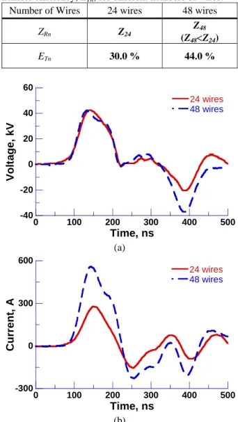
Fig.3 (a) and (b) show the typical waveforms of the ap- plied voltage and the discharge current to the plasma reac- tor for different numbers of wires. The peak value of the applied voltages was 42.4 ± 0.1 kV for both cases. The peak of the current was 278.5 A and 558.9 A for 24 and 48 wires, respectively. The input energy to the plasma reactor per pulse was calculated from the voltage and the current waveforms, and was 0.67 and 1.44 J/pulse for 24 and 48 wires, respectively. The characteristics of these results suggest that the impedance of the plasma reactor decreased with increasing number of wires. This is be- cause a larger number of streamers were produced and a larger current flowed with increasing number of anode wires [5].
Fig. 4 shows the dependence of the NO
Xremoval ratio on the power consumption of the MPC for different num- bers of wires. The power consumption P is
E
chf
P = × (1)
2
2
01
ch
ch
C V
E = (2)
where f, E
ch, C
0, and V
chare the pulse repetition rate [pulse/sec], charging energy of MPC, capacitance of MPC (800 nF), and charging voltage of MPC, respectively.
Fig.4 shows that the NO
Xremoval ratio increased with increasing power consumption and by increasing the number of wires. This means that larger numbers of wires in the plasma reactor are more effective removing NO
Xfrom diesel generator exhaust gases.
Table 1 shows the plasma reactor impedance and the energy transfer efficiency for different numbers of wires.
The plasma reactor impedance, Z
Rn, is calculated from the voltage and current waveforms in Fig.3; and the energy transfer efficiency, E
Tn, is calculated from the charging energy of the MPC, E
ch, divided by the input energy to the plasma reactor. Table 1 indicates that the energy transfer efficiency increased with decreasing plasma reac- tor impedance. Since the impedance of MPC is less that 10 Ω, this result suggests that the lower impedance of the plasma reactor results in a better impedance match with the MPC yielding higher energy transfer efficiency.
Table 1. Plasma reactor impedance, Z
Rn, and energy transfer efficiency, E
Tn, for different numbers of wires.
Number of Wires 24 wires 48 wires
Z
RnZ
24Z
48(Z
48<Z
24)
E
Tn30.0 % 44.0 %
-40 -20 0 20 40 60
0 100 200 300 400 500
24 wires 48 wires
Vo lt ag e, k V
Time, ns (a)
-300 0 300 600
0 100 200 300 400 500
24 wires 48 wires
Curr ent, A
Time, ns (b)
Figure 3. Typical waveforms of the applied voltage (a) and discharge current (b) to the plasma reactor for differ- ent numbers of wires.
1271
0 20 40 60 80 100
0 0.5 1 1.5
24 wires 48 wires
NO
Xre mo va l r a ti o , %
Power consumption, P, kW
Figure 4. Dependence of the NO
Xremoval ratio on the power consumption of the MPC for different numbers of wires.
B. Effects of Wire-to-Wire Distance
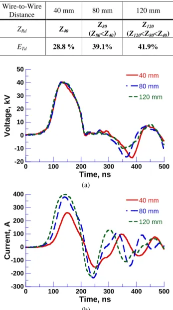
Fig.5 (a) and (b) show typical waveforms of the applied voltage and current for each wire-to-wire distance. The peak value of applied voltages was 40.1 ± 0.4 kV for all cases. The peak current was 260.3, 374.6, and 399.3 A for 40, 80, and 120 mm of wire-to-wire distance, respectively.
The calculated input energy to the plasma reactor was 0.60, 1.01, and 1.17 J for 40, 80, and 120 mm, respec- tively. The characteristics of these waveforms also indi- cate that the impedance of the plasma reactor decreased with increasing wire-to-wire distance.
Fig.6 shows the dependence of the NO
Xremoval ratio on the power consumption of MPC for different wire-to- wire distances. It will be observed from Fig.6 that the NO
Xremoval ratio increased with increasing power con- sumption and increasing neighboring wire distance. Typi- cally, the final removal ratio of NO
Xfor 80 mm is 1.5 times greater than for 40 mm wire-to-wire distance.
Table 2 shows the plasma reactor impedance and the energy transfer efficiency for different wire-to-wire dis- tances. The calculation methods for Z
Rdand E
Tdare the same as in Table 1. From Table 2, it is clear that energy transfer efficiency increased with increasing wire-to-wire distance.
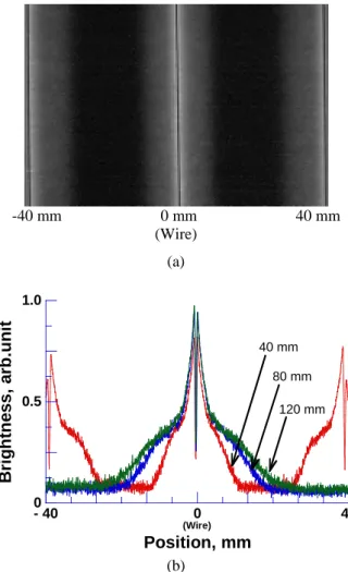
To examine the impedance decrease with decreasing distance between neighboring wires, photographs of pulsed streamer discharges for all wire-to-wire distances were taken. Fig.7 (a) shows a typical photograph for 40 mm wire-to-wire distance. To visualize the differences of the discharges between each wire-to-wire distance, the images were converted into numerical values (Brightness vs. Position) as shown in Fig.7 (b). It will be observed from Fig.7 (b) that the brightness of the streamer dis- charge spread increased in both directions in vertical axis, which means the discharge emission area increased with increasing wire-to-wire distance. This result agrees with the simulated result for a pulsed corona discharge in a wire-to-plate reactor determined by Kim [6]. Kim sug- gests that as the adjacent wire electrodes are brought closer, their interference effects on the electric field dis-
tribution become stronger and the streamers from adjacent wires consequently shrink to considerably narrow ranges.
Kim also recommends that the wire-to-wire spacing should be at least twice the wire-to-plate distance to pro- duce an effective nonequilibrium plasma for enhancing the efficiency of the exhaust gas cleaning process. This recommendation agrees with the experimental results shown in Fig.6.
Table 2. Plasma reactor impedance, Z
Rd, and energy transfer efficiency, E
Td, for different wire-to-wire dis- tances.
Wire-to-Wire
Distance 40 mm 80 mm 120 mm
Z
RdZ
40Z
80(Z
80<Z
40)
Z
120(Z
120<Z
80<Z
40)
E
Td28.8 % 39.1% 41.9%
-20 -10 0 10 20 30 40 50
0 100 200 300 400 500
40 mm 80 mm 120 mm
Vo lt a g e, kV
Time, ns (a)
-300 -200 -100 0 100 200 300 400
0 100 200 300 400 500
40 mm 80 mm 120 mm
Cu rr e n t, A
Time, ns (b)
Figure 5. Typical waveforms of the applied voltage (a)
and discharge current (b) to the plasma reactor for differ-
ent wire-to-wire distances.
0 20 40 60 80 100
0 0.5 1 1.5
40 mm 80 mm 120 mm
NO
Xco nc en tr a ti o n , %
Power consumption, P, kW
Figure 6. Dependence of the NO
Xremoval ratio on the power consumption of the MPC for different wire-to-wire distances.
-40 mm 0 mm 40 mm (Wire)
(a)
0 0.5 1.0
- 40 0 40
B rig htne s s , a rb.un it
Position, mm
(Wire)
40 mm 80 mm
120 mm