東京電機大学
博士論文
「木と鋼のハイブリッド工法の支圧接合部の
力学的性状および構造設計法に関する研究」
The study on structural behavior of the bearing joint and the method
of structural design for timber - steel hybrid structure
平成28年7月
Title:The study on structural characteristics of the bearing joint and the
method of structural design for timber - steel hybrid structure
Summary
In recent years, expectation for materials of higher quality and wider potential-use has coincided with the need for greater spans, longer design lives and lighter weights that adhere to the architect’s visions. Moreover, buildings must consider its local setting, social utility as well as constructability. “Timber-Steel hybrid structural materials” (herein “Timber-Steel hybrids”) have been proposed as a solution to such multifaceted issues. In recent years, government bodies have made concerted efforts to promote the use of timber leading to the completion of numerous buildings of varying use and size utilizing Timber-Steel hybrids.
A critical aspect of designing with Timber-Steel hybrids is the evaluation of its strength at the connection between the timber and steel as outlined in “Standard for Structural Design of Timber Structures” by Architectural Institute of Japan (herein “Timber Standard”). Unlike strength however, deflection of Timber-Steel hybrids are dependent on a set of case-specific factors including the shape of the connection and its material characteristics.
This paper explores empirical methods in assessing Timber-Steel hybrids in terms of their strength, initial stiffness and deflection characteristics, and the paper further studies the applicability of Timber-Steel hybrids as structural elements.
Section 1: Introduction
The introduction provides an overview of Timber-Steel hybrids as well as advantages in their use by studying experiments and examples of previous works, ultimately drawing parallels to this paper.
Section 2: Study on the Mechanical Properties of the Dome structure utilising Timber-Steel hybrid sections held together with bolted joint
(1) trussed wall experiment1 and (2) connection experiment2.
This section further describes the applicability of Timber-Steel hybrids in the construction of Dome structures.
Section 2.1 Overview and features of the Dome structure
This section provides an overview of each of the elements – and their characteristics – that make up the Dome structure.
Section 2.2 Tensile and Compressive experiment of bolted joints with Timber-Steel Hybrid section
Considering the size and design criteria of the Domes structure, seven different bolted joints were chosen from a varying combinations of struts and connections. Compressive and Tensile experiments were carried out on each of these bolted joints. Comparisons were made between the bolted joints to determine differences in their compressive and tensile performances. Such experiments were able to determine the parameters needed for designing the Dome structure including strength, initial stiffness and the ductility factor of each of the seven struts.
Section 2.3 Trussed wall experiment on bolted joints.
In this section, the bolted joints described in the previous section were used to form the trussed wall and subjected to lateral loading experiments. A comparison was made between the tensile and compressive experiments carried out on individual bolted joints in the previous section and the lateral loading experiment of the trussed wall.
The experiments found that stiffness throughout the tensile experiment were similar to those from the compressive experiment after fracture had occurred.
Furthermore, the strength and initial stiffness of each trussed wall is analysed and explained.
Section 2.4 Significance of the experiments for design of Dome structure.
Using the results from the previously mentioned experiments, recommendations are presented on how best to design Dome structures and obtain their ductility factors.
1 Trussed wall experiment involved a triangular truss that is subjected to lateral forces to determine strength, initial stiffness, and the structural characteristic coefficient of the bolted joint.
Moreover, a direct relationship was determined between the ductility factor of bolted joints and a floor’s Structural Characteristic Coefficient regardless of material type or building size as long as the structure in question is a Dome and the materials used are the same for each respective floor.
Section 3: The Development of Earthquake resisting shear walls using Stack-Laminated-Timber
A new hybrid Timber-Steel wall (herein “hybrid wall”) for earthquake resistance was developed using timber cladding/sheeting encased in metallic framing; able to resist external forces by acting as one single unit. In order for the hybrid wall to act
effectively as a single unit, there is a need to prevent cracking in the timber sheeting; often as a result of construction inaccuracies and drying shrinkage. Studies were carried out to verify that the system was able to prevent cracks.
Through experimentation of such hybrid walls, basic properties such as its strength, initial stiffness and ductility factor were found. Moreover, a critique is provided as to the effectiveness of hybrid walls in structural design.
Section 3.1 Properties and characteristics of Earthquake resisting shear walls made of Stacked-Laminated Timber
This section presents the properties and characteristics of (timber-steel) hybrid earthquake resisting shear walls. A planned 3 storey building with a storey height of 3.6m in the metropolitan area provides the basis of this analysis.
Section 3.2 Experiment using Timber-Steel shear walls using Stack-Laminated-Timber This section further explores properties of the timber panel that act as the primary component for earthquake resistance. Further, we validate the structural mechanism behind the hybrid wall. In particular, a relationship is determined between the panel’s grain direction and its compressive strength.
Section 3.3 Experiment of
This section further explores properties of the timber panel that act as the primary component for earthquake resistance. Further, we validate the structural mechanism behind the hybrid wall. In particular, two experiments that verify the in-plane drying shrinkage of the timber panels.
Section 3.4 Horizontal Shear Experiment conducted on the hybrid wall
A horizontal shear experiment was carried out on a full-scale model of the hybrid wall to determine its initial stiffness, strength, and structural characteristic coefficient. Section 3.5 Applicability of the hybrid wall for structural design
This section verified the results from Section 2.3 through Structural Analysis. The results of such analysis concluded that the initial stiffness of the hybrid wall could be predicted from its compressive strain through first-principles.
Furthermore, a relationship was plotted between the strengths of the hybrid wall as determined through the Hankinson equation, and the values obtain from the
compressive strength experiment. This relationship led to the development of a method able to determine the sectional-area of the compressive strut3 in a hybrid shear wall. Section 4: Conclusion
The conclusion of the paper is summarized the results of experimental and analytical study on assessing Timber-Steel hybrids in terms of their strength, initial stiffness and deflection characteristics. The paper further studies the applicability of Timber-Steel hybrids as structural elements, and proposed the estimation method of the structural design for Timber-Steel hybrids as structure.
1-4
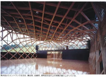
1-13 砥用町林業総合センター(図 1-16,設計:西沢大良建築設計事務所,構造設計:オ ーヴ・アラップ・アンド・パートナーズ・ジャパン・リミテッド)は,外壁側に軽量 鉄骨の柱,屋内側にはスギ材による建物に対して 45°方向に配置した格子状の立体トラ スにより構成している。 図 1-16 砥用町林業総合センター ③ 部材+接合部別ハイブリッドの事例 うつくしま未来博・「21 世紀建設館」(図 1-17,設計:岩村アトリエ,構造設計:
TIS & Partners)は,柱に複数の木材を束ねて鋼製のジョイントプレートを使い,8 本 を組み合わせてひとつの組柱として,構造として一体化させている。
1-14 2) ドーム ドームとは,鉛直方向に作用する力を利用して圧縮力で安定する構造形式であり, 圧縮力に強い木材の特徴が活かされる。ただしドーム形状とする場合は,部材同士の 接合部がピン接合の場合,接合される部材の材軸方向と直交方向(面外方向)に作用 する応力が生じる場合,または曲げ応力が部材の主軸方向に対して複合的に作用する 場合については,設計および現場監理に注意を要する。
出雲ドーム(図1-18,設計:KAJIMA DESIGN,構造設計:KAJIMA DESIGN+斎
第2章
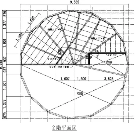
2.1-5 2 階平面図
断面図
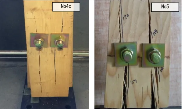
2.2-9 団とした平均値から求めた下限値の推定値(正規分布を仮定した信頼水準75%の 95%下 限許容限界値,以下 5%下限値)にもとづき,各実験結果における終局耐力の実験値 ePu の 5%下限値による終局耐力の実験値 ePu’を算出した。 (a) 引張(No4)および圧縮(No4c)実験結果の比較 各試験体とも 5%下限値による終局耐力の実験値 ePu’が概ね終局耐力の計算値 cPu を 上回ることが確認された。また引張実験結果と比較して,圧縮実験結果の 5%下限値に よる終局耐力の実験値ePu’のほうが 14%程度高いことが確認された。これは圧縮側のほ うが最大荷重時まで木材の割裂が顕著に現れていない状態が維持されたことが影響し ていると考えられる。 初期剛性については,圧縮実験は加力初期段階よりボルトと木材が接触状態にて加 力しているが,引張実験はガセットプレートに設けられたボルトクリアランスにより, 加力初期においてスリップ挙動を示した影響により,このスリップ挙動を含めた接合 部の初期剛性は圧縮実験結果のほうが 3.8 倍程度高い結果となったが,引張実験結果の 第2 剛性と圧縮実験結果の初期剛性を比較すると,概ね近い傾向が見られた。 (b) ストラット材に用いる樹種の違いによる影響 各試験体とも 5%下限値による終局耐力の実験値 ePu’が概ね終局耐力の計算値 cPu を 上回ることが確認された。一方,ストラット材の種類による耐力のばらつきについて は,5%下限値による終局耐力の実験値 ePu’および最大荷重 Pmax ともに,平均値に対す る5%下限値耐力の低減率は,S シリーズは約 24~46%程度に対して,L シリーズは約 8 ~16%程度の低減率であったことから,L シリーズのほうが全体的に耐力のばらつきの
影響が小さい傾向が見られた。またL シリーズの No7c の終局耐力 ePu を No7 の引張実
2.2-10
図 2.2-5(a) 荷重変形曲線(No1)
2.2-11
図 2.2-5(c) 荷重変形曲線(No3)
2.2-12
図 2.2-5(e) 荷重変形曲線(No4)
2.2-13
図 2.2-5(g) 荷重変形曲線(No7)
2.2-14
2.2-15 (4)ボルト接合部の塑性率およびばらつきの評価 引張および圧縮実験結果より得られたボルト接合部の塑性率を表 2.2-3 に示す。実験 結果より得られた塑性率のばらつきについては,降伏耐力の実験値ePu’の算出方法と同 様に,各実験結果から得られたボルト接合部の塑性率のばらつきを考慮して,5%下限 値の考え方を用いた特性値を求めた。ボルト接合部の塑性率のばらつきを考慮した特 性値(以下,sDs)は,以下の方法により算出する。 ① 引張または圧縮実験結果より,木質構造設計規準・同解説 2-3)により算出された 各試験体の終局耐力の実験値ePu,降伏点変位δv,終局耐力時変位δu を用いて 得られる塑性率μを,各試験体それぞれについて算出する。 ② 各試験体の塑性率μを用いて,ボルト接合部の特性値sDs を各試験体それぞれに ついて,式2.2-1 により算出する。
1
2
1
s
s
D
③ ボルト接合部の特性値 sDs に加えて 1 となるような補数 sD's を式 2.2-2 により求 める。s
s
s
s
D
'
1
D
④ 同一試験体数分の sD's のばらつきを評価するため, sD's の 5%下限値 sD'su を算 出する。 ⑤ 以上より得られた sD'su に加えて 1 となるような補数として,ばらつきを考慮し て得られたsD''s を式 2.2-3 にて算出し,ここで得られた sD''s を,各試験体のばら つき考慮したストラット材を有するボルト接合部の特性値sDs と読み替える。su
s
s
s
D
''
1
D
'
この方法により,本実験で得られた S シリーズの代表的なボルト接合部の特性値 sDsは ,No2 : sDs=0.544 ( 標 準 偏 差 σ =0.039 ) , No3 : Ds=0.488 ( σ =0.048 ) , No4 : sDs=0.477(σ=0.084),No4c:sDs=0.265(σ=0.033),L シリーズの代表的な特性値 sDs は,No5:Ds=0.639(σ=0.067),No6:0.725(σ=0.042),No7:0.597(σ=0.027)
・・・・・・・式2.2-1
・・・・・・・式2.2-2
2.3-5
a)全体最終破壊状況
2.3-6
a)全体最終破壊状況
2.3-7 (2)荷重変形関係
各試験体の履歴曲線,および得られた荷重変形関係から,木質構造設計基準・同解
説2-3)の方法により求めたモデル化曲線を図2.3-7 に示す。縦軸は試験体頂部に作用させ
た水平荷重を,横軸は頂部に設置した変形計による水平変位量の計測値および変形角
をあわせて示す。図中の実線が No1 の試験体の履歴曲線を示し,No2 および No3 試験
2.4-4
C=0.261)を前述の式 2.2-1 に代入して得られた値(引張:2.698,圧縮:7.840) を,本解析に用いる塑性率μとする。
本解析に用いる解析ソフトは,部材の非線形性を考慮した静的立体解析が可能な
Sein La CREA(NTT DATA 社製)を用いる。
2.4-8
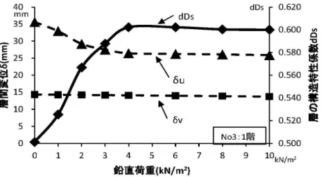
図 2.4-6(a) ドーム型構造に作用する鉛直荷重とドーム構造の構造特性係数 dDs との関係-1
図 2.4-6(b) ドーム型構造に作用する鉛直荷重とドーム構造の構造特性係数 dDs との関係-2
2.4-9
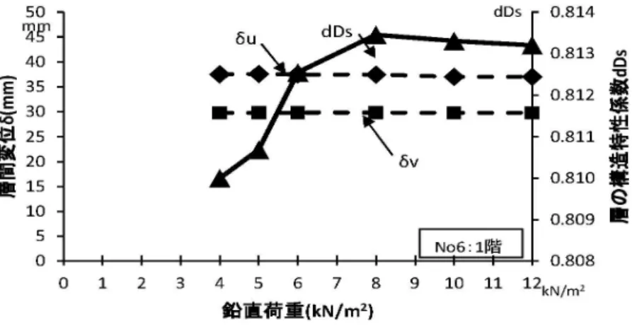
図 2.4-6(d) ドーム型構造に作用する鉛直荷重とドーム構造の構造特性係数 dDs との関係-4
図 2.4-6(e) ドーム型構造に作用する鉛直荷重とドーム構造の構造特性係数 dDs との関係-5
2.4-10
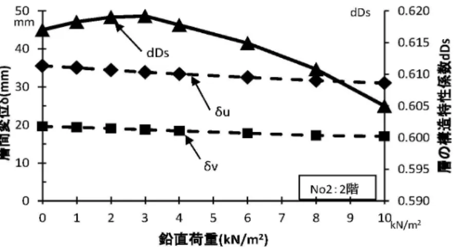
図 2.4-6(g) ドーム型構造に作用する鉛直荷重とドーム構造の構造特性係数 dDs との関係-7
図 2.4-6(h) ドーム型構造に作用する鉛直荷重とドーム構造の構造特性係数 dDs との関係-8
2.4-12
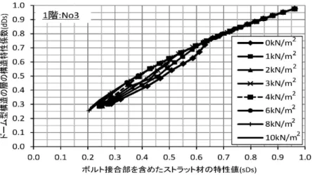
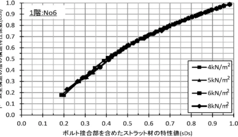
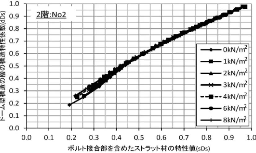
図 2.4-7(a) 接合部の特性値 sDs とドーム型構造の層の構造特性係数 dDs との関係-1
図 2.4-7(b) 接合部の特性値 sDs とドーム型構造の層の構造特性係数 dDs との関係-2
2.4-13
図 2.4-7(d) 接合部の特性値 sDs とドーム型構造の層の構造特性係数 dDs との関係-4
図 2.4-7(e) 接合部の特性値 sDs とドーム型構造の層の構造特性係数 dDs との関係-5
2.4-14
図 2.4-7(g) 接合部の特性値 sDs とドーム型構造の層の構造特性係数 dDs との関係-7
図 2.4-7(h) 接合部の特性値 sDs とドーム型構造の層の構造特性係数 dDs との関係-8
第3章
3.1-3
図 3.1-3 水平力の抵抗機構
図 3.1-4 乾燥収縮時の接合金物の挙動
3.4-6
図 3.4-4(a) 実験方法および測定項目(SFW 試験体)
3.4-12
a)全体の破壊状況
b)柱脚部の破断状況
3.4-13
a)全体の破壊状況
b)木質パネル脚部のめり込み状況
3.4-14
a)全体の破壊状況
b)木質パネルのせん断破壊状況
3.4-15
a)全体の破壊状況
b)木質パネル脚部のめり込み状況
3.4-16
a)木質パネル頂部のめり込み破壊状況
3.4-17
a)木質パネル頂部のめり込み破壊状況