Studies on Network Traffic Engineering Exploiting Dynamic IP-Flow Characteristics
(動的なIPフローの特性を利用したトラヒックエンジニアリング技術に関する研究)
Yoshinori KITATSUJI
Preface
Due to advances of the Internet, various distributed applications are commonly used and thus, traffic type traversing the Internet diversifies according with increase of the application variation. Network traffic engineering (TE) which distributes traffic over multiple routes (paths), efficiently utilizes the network resource and relieves the contention of the network resource. Such effectiveness rises when TE applied on a backbone network admitting huge amounts of traffic. The conventional methods for TE generally take the utilization of individ- ual paths into account for traffic distribution. However, there is a nature that even constant bit-rate traffic suffers from high delay variation as much as the highly burst traffic does when a path involves both types of traffic, if its utilization is high. This dissertation discusses TE which distinguishes flows from traffic to have a certain traffic characteristics and reduces delay variation of the flows as a whole by exploiting the characteristics when the flows are distributed over multiple paths.
For this study, the future backbone network is considered to have two layer structure, a core network and edge routers surrounding it, for the sake of dealing with huge amounts of traffic, e.g., thousands Gbit/s or more in total. It is assumed that multiple bandwidth- guaranteed paths are established between each pair of the edge routers and routed over the core network. And the edge routers handles assigning flows to one of the paths to distribute traffic over the core network. In this assumption, the edge routers are considered to have two functions, measuring the traffic characteristics of flows and assigning flows to one of paths with their characteristics. This dissertation studies the individual functions along with
First, the availability of the real-time IP-flow monitoring on the high-speed link, e.g., 10 Gbit/s, is studied through developing a traffic monitoring tool dealing with huge amounts of flows. Second, the effectiveness of TE focusing on traffic flows is studied through two analyses using the real traffic with the developed IP-flow monitoring tool. One analysis is for TCP flows of GRID applications. This analysis indicates that when multiple GRID ap- plications simultaneously run in a network, effective bandwidth assignment for a set of flows from applications differs depending on their traffic patterns. E.g. application traffic includ- ing highly bursty flows should have an exclusive path since it degrades the other application performance if aggregated to a single path, while application traffic with small changes of traffic rate can be aggregated into a single path with other similar applications without large degradation of application-level performance. The other analysis is for UDP flows with VoIP traffic. This analysis finds that VoIP traffic mainly involves distinctive flows, that is, fix packet length and almost fix inter-packet gap. The analysis leads to developing a lightweight VoIP flow monitoring method exploiting the VoIP flow features. Third, a flow assignment method for reducing the queuing delay in the case of two distinctive flow sets assigned to two different bandwidth paths is developed. The contribution of this method is that it finds the approximate flow assignment within a short period so as to be used in the real environment.
Findings clarified in these studies are 1) feasibility of developing scalable flow-based traffic measurement method, 2) effectiveness of introducing the traffic characteristics on in- dividual flows acquired by traffic measurement into the TE, and 3) effectiveness of a devel- oped flow assignment method exploiting the traffic characteristics on flows. These results greatly contribute to effective improvement of QoS in TE.
Finally, I hope that this dissertation will be helpful for further studies in this field.
March 2007 Yoshinori KITATSUJI
Acknowledgements
First and foremost, I thank my family, especially my wife, Hidemi, who challenged me to
“do the best you can, then let it go.” Better advice has never been uttered.
I wish to express my sincere appreciation to Professor Masato Tsuru of Kyushu Institute of Technology. His constant encouragement, guidance through this research, valuable dis- cussions and advice have greatly helped in accomplishing the research. I also thank him for his careful reading of all papers on these studies.
I would also like to express my gratitude to Professor Katsuyuki Yamazaki of Nagaoka University of Technology and Professor Yuji Oie of Kyushu Institute of Technology for their valuable comments, time, and help in completing these studies. Their steady supports have greatly helped my study.
I wish to thank Professor Tetsuya Takine of Osaka University, Assistant Professor of Hiroshi Koide of Kyushu Institute of Technology, and Mr. Satoshi Katsuno in KDDI R & D Laboratories, Inc. for their valuable discussions and comments.
I would like to express my gratitude to Mr. Kazunori Konishi in KDDI R & D Labora- tories, Inc., Assistant Professor Akira Kato of University of Tokyo, Dr. Katsushi Kobayashi in National Institute of Advanced Industrial Science and Technology, and Mr. Yasuichi Ki- tamura in NICT concerning the work in Chapter 2 for their precise works and comments.
Without their assistance and advice on network designing and operations, I would not be able to maintain Tokyo exchange point in APAN, and to construct knowledge of what IP network is and understanding how it works.
encouragements. Without them, I would not concentrate to drive myself to study in Ki- takyushu where almost topics in this dissertation have been studied.
I extend thanks to Dr. Kazmumi Kumazoe, Dr. Hiroyuki Koga, Dr. Nobuo Ryoki and all other members of NICT Kyushu Research Center for their kindly supports and invaluable discussions.
Contents
Acknowledgements 5
1 Background and Scope of these Studies 1
1.1 Introduction . . . 1
1.2 Network Traffic Engineering . . . 3
1.3 Structure of These Studies . . . 5
2 Backbone Network Architecture 9 2.1 Summary of APAN Tokyo XP . . . 10
2.1.1 International Links and Acceptable Usage Policy . . . 10
2.1.2 Network configuration . . . 13
2.1.3 Network Operations . . . 13
2.1.4 Monitoring Tools . . . 14
2.1.5 Routing . . . 15
2.1.6 IPv4 Unicast . . . 15
2.1.7 IPv4 Multicast . . . 17
2.1.8 IPv6 . . . 18
2.2 Evaluation of Policy-base Routing Scheme . . . 18
2.2.1 Experimental Environment . . . 18
2.2.2 Packet Forwarding Performance . . . 20
2.3 Consideration of Backbone Network Architecture . . . 21
2.4 Conclusion . . . 22
3 Development of Real-time IP-Flow Monitoring Tool with Scalable Architec- ture 25 3.1 Introduction . . . 25
3.2 Related Works . . . 26
3.3 Requirements in Network Operations . . . 28
3.3.1 Flow Measurement . . . 28
3.3.2 Requirements . . . 28
3.3.3 Issues . . . 30
3.4 Proposed System . . . 31
3.4.1 Enhancement of Component . . . 31
3.4.2 Proposed Architecture . . . 33
3.4.3 Flow Definition and Data Structure . . . 36
3.4.4 Measurement Attribute . . . 37
3.5 Implementation Issues . . . 39
3.5.1 Implementation with PC-UNIXs . . . 39
3.5.2 Time Synchronization . . . 40
3.5.3 Flow ID Search . . . 41
3.6 Evaluation . . . 42
3.6.1 Evaluation Environment . . . 43
3.6.2 Performance Difference in Deploying or Not Deploying the Packet Buffering Process . . . 45
3.6.3 Performance Difference in Deploying AVL Tree Search or Sorted List Search . . . 46
3.6.4 Scalability Evaluation . . . 47
3.7 Discussions . . . 48
3.7.1 Evaluation Results . . . 48
CONTENTS
3.7.2 Performance . . . 51
3.7.3 Timestamp Accuracy and Distribution . . . 52
3.8 Application and Advantage of Flow Measurement . . . 53
3.8.1 Example Real World Environment . . . 53
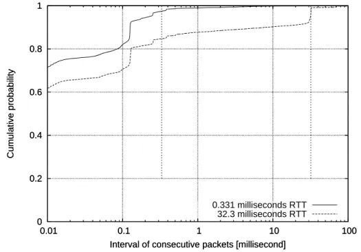
3.8.2 RTT Measurement . . . 54
3.9 Conclusions . . . 58
4 Influence of network characteristics on application performance in a Grid environment 59 4.1 Introduction . . . 59
4.2 Distributed Computing Applications . . . 62
4.3 Experimental Environment . . . 63
4.4 Analysis of Communication Features . . . 64
4.5 Influence of Network Properties on Application-level Performance . . . 70
4.5.1 Impact of Large Round-trip Time . . . 70
4.5.2 Impact of Limiting the Bandwidth of the Bottleneck Link . . . . 73
4.5.3 Impact of both Expanding RTT and Limiting Bandwidth of Bottle- neck Link . . . 75
4.6 Influence of Application Traffic on Other Traffic . . . 77
4.6.1 Influence of Application Traffic on UDP Traffic . . . 78
4.6.2 Influence of Application Traffic on Performance of Other Applica- tions . . . 80
4.7 Example of Simple Traffic Engineering Based on the Application-Level Performance . . . 83
4.7.1 Example Scenario . . . 83
4.7.2 Deriving Most Suitable Bandwidth . . . 85
4.7.3 Efficiency of Shaping Application Traffic Individually . . . 85
4.8 Conclusion . . . 88
5 Performance Monitoring of VoIP Flows for Large Scale Network 91
5.1 Introduction . . . 91
5.2 Related Works . . . 93
5.3 Performance Monitoring of VoIP Flows . . . 94
5.3.1 Monitoring Locations in Backbone Network . . . 94
5.3.2 Identification of VoIP Flows . . . 95
5.3.3 Metric Representing Degradation of VoIP Flows . . . 97
5.4 Characteristics of VoIP Flows . . . 98
5.5 Proposed Method . . . 102
5.5.1 Metric Definition for Delay Variation and Rate of Consecutive Packet Loss . . . 102
5.5.2 Algorithm to Register Monitored VoIP Flows . . . 104
5.6 Performance Evaluation . . . 105
5.6.1 Accuracy . . . 105
5.6.2 Number of Monitored Flows . . . 108
5.7 Applying Proposed Method to Real Monitoring Operation . . . 110
5.8 Conclusions . . . 112
6 Traffic Characteristics-aware Flow Assignment Method for Reducing Queu- ing Delay 115 6.1 Introduction . . . 115
6.2 Related Work . . . 118
6.3 Flow Assignment Problem and Analytical Model . . . 120
6.3.1 Approach . . . 120
6.3.2 Delay Metric Representing Delay Performance for Two Paths . . 122
6.3.3 Fluid Flow Model-Based Analysis . . . 123
6.3.4 Relationship between Delay Metric and Best Flow Assignment . 126 6.4 Effectiveness of Traffic Characteristics-aware Flow Assignment . . . 129
CONTENTS
6.4.1 Best Flow Assignment under Same-bandwidth Paths . . . 130
6.4.2 Best Flow Assignment under Different-bandwidth Paths . . . 132
6.4.3 Summary . . . 136
6.5 Flow Assignment Method . . . 137
6.5.1 Queuing Delay Characteristics . . . 138
6.5.2 Algorithm for Approximately Placing Delay Contour Lines . . . 140
6.5.3 Search for Best Flow Assignment . . . 142
6.5.4 Evaluation . . . 143
6.6 Conclusion . . . 145
7 Concluding Remarks 149 7.1 Summary of this dissertation . . . 149
7.2 Issue for Future Research . . . 152
Bibliography 155
List of Figures
1.1 Scope and structure of these studies . . . 6
2.1 International links in APAN . . . 12
2.2 Physical network configuration . . . 14
2.3 Policy-based routing scheme . . . 17
2.4 Network configuration for the PBR performance evaluation . . . 19
2.5 Packet forwarding performance . . . 20
3.1 Architecture of a distributed real-time flow measurement tool . . . 35
3.2 Example of hierarchical chained bit-patterns . . . 37
3.3 Configuration of performance evaluation . . . 44
3.4 Configuration of entire system performance test . . . 45
3.5 Process performance per number of bit-patterns with or without the packet buffer . . . 47
3.6 Process performance per range size of bit-pattern with AVL tree search or sorted list search . . . 48
3.7 Performance of entire system . . . 49
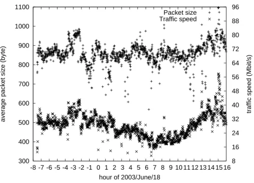
3.8 Packet length of traffic passing between APAN and WIDE . . . 50
3.9 Flows of outgoing traffic to WIDE . . . 53
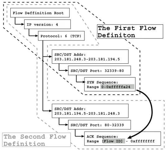
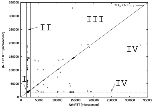
3.10 An example of flow definitions to collect RTTs from a TCP connection . 55 3.11 An Example of Phase Plot Showing Different Congestion Region . . . . 56
4.1 Network configuration . . . 63 4.2 Fluctuation of throughput of NQueen and LU Decomposition. X-axis is the
elapsed time in seconds after applications start. Throughput of 10 ms average is on y-axis. Positive values on y-axis indicate traffic incoming to PC3 while negative values indicate outgoing traffic. . . 65 4.3 Fluctuation of throughput of Jigsaw Puzzle and Task Scheduling. X-axis is
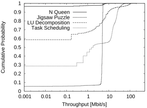
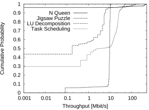
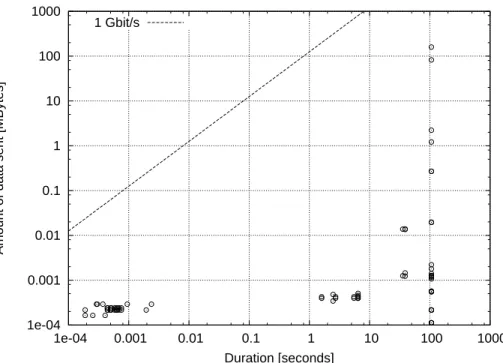
the elapsed time in seconds after applications start. Throughput of 10 ms average is on y-axis. Positive values on y-axis indicate traffic incoming to PC3 while negative values indicate outgoing traffic. . . 66 4.4 Cumulative probability of throughput of input traffic for each application 67 4.5 Cumulative probability of throughput of output traffic for each application 68 4.6 Duration and amount of data transferred in each flow generated in N Queen:
Line is boundary of plots and is equivalent to 1 Gbit/s. . . 69 4.7 Duration and amount of data transferred in each flow generated in Task
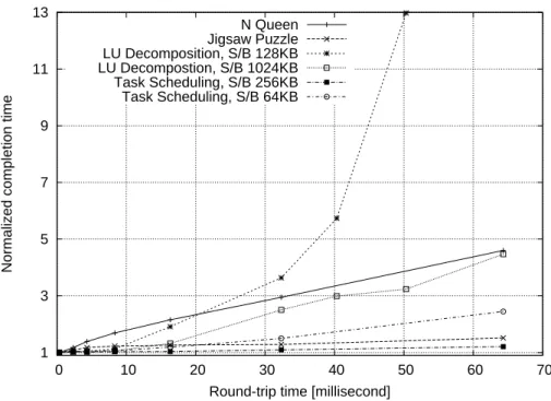
Scheduling: Line is boundary of plots and is equivalent to 1 Gbit/s. . . 70 4.8 Completion time influenced by RTT: Application-level performance deteri-
orates as RTT increases. . . 71 4.9 Distribution of inter-packet gaps in flows generated by N Queen . . . 73 4.10 Distribution of inter-packet gaps in flows generated by Jigsaw Puzzle . . 74 4.11 Completion time influenced by narrow bottleneck link . . . 76 4.12 Completion time influenced by the narrow bottleneck link and RTT for N
Queen . . . 77 4.13 Completion time influenced by narrow bottleneck link and RTT for Jigsaw
Puzzle . . . 78 4.14 Completion time influenced by narrow bottleneck Link and RTT for LU
Decomposition . . . 79
LIST OF FIGURES
4.15 Completion time influenced by narrow bottleneck link and RTT for Task Scheduling . . . 80 4.16 Packet loss ratio of UDP cross traffic sharing bottleneck link with application
traffic . . . 81 4.17 Completion time of N Queen influenced by other applications . . . 82 4.18 Completion time of LU Decomposition influenced by other applications . 83 4.19 Network configuration for traffic engineering demonstration . . . 84 4.20 The completion time of N Queen and approximated performance functions 86 5.1 Location of monitoring tools in backbone network. An IX is an Internet
exchange point. . . 95 5.2 Cumulative distribution of average packet length for UDP flows of more
than a certain duration. . . 99 5.3 Cumulative distribution of average IPG for UDP flows lasting more than 10
seconds in a range of packet lengths. . . 100 5.4 Packet arrivial process for flow i. . . . 102 5.5 Q-Q plot of actual packet loss rate for all inserted flows (X axis) and de-
graded packet rate of sampled flows (Y axis) when buffer size was limited to that at which maximum queuing delay of 10 ms. . . 106 5.6 Q-Q plots of standard deviation of actual IPGs (X axis) and the average
difference of IPGs (Y axis) for all inserted flows. . . 107 5.7 Q-Q plots of the average difference of IPGs for all inserted flows (X axis)
and for sampled flows (Y axis). . . 108 5.8 Q-Q plot on relationship between average and 99.5th percentile of differ-
ences from the ideal IPG in each period of ideal IPG (0.02 s). . . 109 5.9 Flow monitoring algorithm. Parameters, N, ˜X, [Lmin, Lmax), and T , are set
to, for example, 100, 0.02 seconds, 200 or 201 bytes, and 10 seconds. . . 113
6.1 Simple case considered in this chapter: a number of flows, each having one of two distinct sets of traffic characteristics, are assigned to one of two paths with different bandwidths. . . 117 6.2 Infinite buffer accommodating two types of on-off fluid flow . . . 124 6.3 The mean of queuing delay for two path with the total utilization 0.6 . . . 126 6.4 The 99.5th percentile of queuing delay for two path with the total utilization
0.9 . . . 128 6.5 Min-max delay for mean queuing delay for traffic combination 1 distributed
over two 6-Mbit/s paths . . . 130 6.6 Weighted-log delay for mean queuing delay for traffic combination 2 dis-
tributed over two 6-Mbit/s paths . . . 132 6.7 Min-max delay for the mean queuing delay for traffic combination 1 dis-
tributed over 4-Mbit/s and 8-Mbit/s paths . . . 133 6.8 Weighted-log delay for mean queuing delay for traffic combination 2 dis-
tributed over 4-Mbit/s and 8-Mbit/s paths . . . 134 6.9 Delay contour line for 99.5mboxth percentile queuing delay against ratio of
class-1 flows and average path utilization for a single path. . . 139 6.10 Improvement under the min-max delay strategy . . . 144 6.11 Improvement under the max weighted log-sum delay margin strategy . . 145 6.12 The 99.5th percentile of queuing delay for estimated flow assignment with
min-max delay for the case of only 20 sample data and the 80 % utilization 146 6.13 The 99.5th percentile of queuing delay for estimated flow assignment with
weighted-log delay for the case of only 20 sample data and 80 % utilization (D= 0.1 s) . . . 147
List of Tables
2.1 International links in APAN . . . 11
3.1 Comparison of requirements enabled by different measurement systems . 30 3.2 Elements specifying the bit-pattern . . . 36
3.3 Specification of PC-UNIXs used for evaluation . . . 46
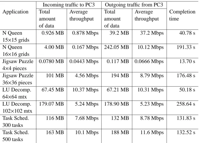
4.1 Feature of traffic to/from a computer for each application . . . 64
4.2 Number of packets transferred in applications influenced by various round- trip times . . . 75
4.3 Bottleneck bandwidths at which completion time deteriorates gradually or severely . . . 75
4.4 Demonstration scenario . . . 87
4.5 Performance in non-shaping case . . . 87
4.6 Performance in shaping case . . . 88
5.1 Characteristics of traffic traces. . . 101
6.1 Path combinations over which traffic flows are balanced . . . 129
6.2 Traffic characteristics and combinations of two traffic classes . . . 129
6.3 Number of flows classified based on peak rate . . . 135
6.4 Flow assignment maximizing the min-max delay for each number of flows on individual traffic combinations . . . 136
Chapter 1
Background and Scope of these Studies
1.1 Introduction
Due to advances of the Internet, various distributed applications are generally used and thus the characteristics of traffic traversing the Internet now diversifies according with increase of the application variation. So far, the Internet Service Providers (ISPs) had been facing increasing the capacity of admitted traffic, while in addition they simultaneously challenge to keep the traffic of the multiple services, such as, conventional text-based file transmission, voice-over-IP (VoIP), IP Television and etc, high quality and stationary when these services are provided in their single network.
One of the network traffic engineering (TE) using multiple communication paths (simply called paths hereafter) to distribute incoming traffic over a network can increase capacity of the admitted traffic. Conventionally, the traffic distribution equally balances traffic over the multiple paths based on the link capacity, that is, making the link utilization equalized [AAA+02] [SdV01] [SGD03]. Then, the distribution usually exploits destination IP address of the traffic, resulting in that multiple service traffic with the distinct characteristics, such as burst and constant bit-rate (non-burst) traffic, are assigned to an identical path. Thus, there is an essential problem that the burst traffic heavily increases the delay variation when the link is highly utilized, leading to that the non-burst traffic accommodated in the same path also encounters the heavy delay variation [SB02] [TV00] [XG02]. TE exploiting the traffic characteristics of flows, e.g., constant bit-rate and burstiness, for improving QoS when the
path is highly utilized is studied in this dissertation. Here, a flow is defined as a sequence of packets distinguished by tuples, that is, the single or the multiple fields in IP- and transport- layers headers. The combination of tuples is depends on how the flows are distinguished from the others, such as, a flow distinguishing source and destination port in transport-layer as described in Chapter 5, or a flow distinguishing applications executed over multiple hosts as described in Chapter 4
A backbone dealing with huge amounts of traffic is considered to have an two-layer structure, a core network to aggregate traffic traversing the backbone network, and edge routers where the traffic enters or leaves the backbone network. Exclusive routers having simple packet-forwarding mechanism are placed in the core network leading to exchang- ing huge amounts of traffic, while the edge router has higher functionality (more complex processing) than ones in the core network, since the traffic treated by the former router is lower than the latter. In addition, the individual pair of the edge routers establishes multiple bandwidth-guaranteed paths routed over the core network in order to properly distribute traf- fic forwarded through the paths over the core network. In this structure, the individual edge router is required to equip two functions: measuring of the traffic characteristics of each flow, and appropriately balancing the flows over the multiple paths by assigning flows to the paths with the identified traffic characteristics. For this traffic characteristic-aware TE, two-folds are studied:
• a method measuring the flows traversing a high-speed link, and
• a method properly balancing flows over multiple paths in terms of a queu- ing delay in a buffer of the first link of each path.
The scalable flow measurement method is studied through developing a real-time IP-flow monitoring tool. The efficiency of the flow measurement is indicated through the analysis of two types of applications with the developed tool: distributed computing applications using TCP flows, and VoIP traffic composed of UDP flows. For the TCP-flow analysis the rela- tionship of network properties and application traffic is analyzed in terms of improving the
1.2. NETWORK TRAFFIC ENGINEERING
application-level performance (completion time) of the distributed computing applications.
The fact that the effective way to allocate a bandwidth-guaranteed path to the single or mul- tiple applications depends on the traffic pattern of them is found when multiple types of the applications run over a single network. For the UDP-flow analysis a lightweight method exposing VoIP flows and performance metrics representing the QoS level of VoIP flows are developed.
For the study on the queuing delay-aware flow distribution, a flow balancing method for the simple situation that two types of flows with distinct characteristics are balanced over two different bandwidth paths through the following two steps. The first step is confirming that balancing the ideal flows grouped into two types over two paths can reduce queuing delay by some tens folds compared to the path utilization-based balancing. The second step is developing a method finding the approximately optimal flow assignment exploiting several sample data of the previous flow assignment and its queuing delay without the information on the detailed traffic characteristics. The method enables the flow assignment to reduce the queuing delay by multiple folds.
Through these studies, it is proved that the following three-folds are effective for prevent- ing the severe quality-degradation when flows are admitted to the highly utilized backbone network: the scalable flow measurement, the TE focusing on exploiting the traffic charac- teristics observed by the developed flow measurement tool. and the generic flow-balancing method taking into account the traffic characteristics of flows.
1.2 Network Traffic Engineering
The Internet has been growing, as real-time traffic, such as, VoIP, IPTV, and so forth, has been increasingly conveyed besides the conventional file transmission in the Internet. The backbone network, e.g., the Internet service providers (ISPs), faces to emerge providing various types of traffic with the QoS required by their customers.
TE properly and dynamically allocates the network resources to such various types of
traffic according with the network situation [AMA 99]. Although there exist variety of TE definition, the goals of TE are grouped into the followings:
1. improving the network fault tolerance 2. increasing the capacity of admitted traffic
3. improving the QoS of input traffic as a whole or a part 4. guaranteeing the QoS of admitted traffic.
1. avoids the communication inavailability, such as, discarded or loops by rerouting the traffic after the network problem happening. This is achieved by the effective protection and restoration of links or paths. The protection recoveries a fault with a pre-computed path while the restoration recoveries with a path created after detecting the fault. Conventionally, the link-level recovery was done for SONET and FDDH which continuously monitor link status and receiving frames. The path-level recovery was done by routing protocol and used to require long restoration time in the order of seconds to minutes. Multi-protocol label switching (MPLS) [AMA+99] is now one-solution to make the recovery more flexibly and faster [SE03]. There are various methods for finding the dedicated path for the protection and computing restoration path.
2. is achieved by optimizing link costs of link-state routing protocol, or balancing traffic over the multiple routes for each traffic path effectively [Kaw04] [SdV01]. Although the former method uses the single path for each traffic path, the capacity improves by 1.5 times more than that from the general cost setting, such as, in the in-proportional way to the link bandwidth [FT00]. In the latter cases, early traffic balancing is limited to be used with multiple equal-cost or relaxed equal-cost paths [SGD03], [Vil99]. These were for the sake of avoiding loop for packet forwarding using the routing table constructed by conventional defact-standard routing protocols, such as, RIP, OSPF, IS-IS. In the cases of use for label switch path (LSP) of MPLS, PVC of ATM, or VLAN of Ethernet, not only the shortest path but also the k-shortest paths algorithms are used to find an multiple paths. Topkis proposed
1.3. STRUCTURE OF THESE STUDIES
the enhanced algorithm of Djikstra so that OSPF discovers k routes [Top] in the order of the low cost. The algorithm is given the maximum path cost C and discovers the lowest cost route in all the routes without more than the path cost C. Chen proposed the k-largest bandwidth path algorithm exploiting the bandwidth of a link as a metric, where the best route has the largest metric in all the candidate routes [Che99].
3. avoids the degradation of traffic characteristics as a whole or a part of incoming traffic when whole traffic is accepted to be conveyed in the backbone network (without admission control). This type of TE also uses multiple paths as 2. does. Most difference from 2. is how balance traffic over the multiple paths. 3. generally equalizes the utilization of individ- ual paths over which traffic is distributed, while 3. uses other criteria related to the delay variation related to the delay variation and packet loss with the measurement-based informa- tion on traffic characteristics [EJLW01] [GKL+04]. In the 2. case, the network resource are optimally allocated under the variety of fairness definitions.
4. increases the admitted traffic which has variety of QoS requirements. The difference from 3. is the admission control is generally adopted to achieve the QoS requirement of the admitted traffic [KKL00]. 3. and 4. are called measurement based routing in the cases to compare with the conventional routing methods which do not use network dynamics or do use only the link utilization [GCL04a].
Studies in this dissertation are classified into 3. These studies first consider the structure of backbone network which deals with huge amounts of traffic and equips functions to mea- sure traffic characteristics in it Second, the measurement method dealing with large amounts of flows is considered. Lastly, The flow assignment method balancing the delay variation over multiple paths is proposed.
1.3 Structure of These Studies
Figure 1.1 illustrates structure of these studies. The following are brief summary of each study and associated Chapter.
Chapter 2:
backbone network architecture
Chapter 6:
traffic characteristics- aware flow assignment for lowering queuing delay
Analysis of relations between IP-flow traffic characteristics and network properties influencing on application performance
Section 3:
development of real- time IP-flow monitoring tool with scalable architecture
Section 4:
influence of network characteristics on application performance in Grid environment
Section 5:
performance monitoring of VoIP flows for large scale network
Figure 1.1:Scope and structure of these studies
• Chapter 2: Backbone Network Architecture describes Asia-Pacific Ad- vanced Network (APAN) [LW00] and reviews the network configuration and operations of APAN Tokyo exchange point (XP), and policy based routing scheme with multiple routers adopted in Tokyo XP. The multi- ple router scheme is evaluated and shows to have the sufficient packet- forwarding performance compared to the requirement in Tokyo XP. The results discussed in this chapter are mainly taken from works [KKK+02].
Through these reviews and performance evaluation, the chapter clarifies the requirements for a backbone network providing the better QoS among traffics with the various traffic characteristics.
• Chapter 3: Development of Real-time IP-flow Monitoring Tools with Scal- able Architecture describes the architecture for a scalable real-time flow measurement tool in order to allow network operators to flexibly de-
1.3. STRUCTURE OF THESE STUDIES
fine “the targeted flows” on-demand, to obtain various statistics on those flows, and to visualize them in a real-time manner. A traffic distribution device and multiple traffic capture devices processing packets in parallel are included in the architecture, in which the former device copies traffic and distributes it to the latter devices. The performance evaluation with a proto-type implementation on PC-UNIX in testbed experiments shows the proposed architecture has the scalability and the advantage of flexible fine-grained flow measurements. The results discussed in this chapter are mainly taken from works [KYTO04] [KKY+07].
• Chapter 4: Influence of Network Characteristics on Application Perfor- mance in a Grid Environment describes analysis of the relation between the characteristics of traffic generated by typical grid applications, and the effect of the round-trip time and bottleneck bandwidth of network on the application-level performance (i.e., completion time) of these appli- cations. The analysis shows that the impact of network conditions on the performance of various applications and the impact of application traffic on network conditions differ considerably depending on the application.
These results suggest that effective allocation of network resources must take into account the network-related properties of individual applica- tions. The results discussed in this chapter are mainly taken from works [KYK+05].
• Chapter 5: Performance Monitoring of VoIP Flows for Large Scale Net- work describes a method for scalable performance monitoring of VoIP traffic flows distinguished by five tuples, that is, IP addresses, protocol, and port numbers. This method extracts the VoIP flows in a lightweight manner, and estimates the packet loss rate and the delay variation by ex- ploiting the features of actual VoIP flows, that is, fixed packet length and
fixed inter-packet gaps (IPGs) which are relatively common among most VoIP flows. The evaluation by simulation with trace data of actual traffic shows that monitoring only 2 % or less of the total VoIP flows can accu- rately estimate the delay variation of the total VoIP flows, while 20 % or more of the total VoIP flows are required in order to estimate the packet loss rate.
• Chapter 6: Traffic Characteristic-aware Flow Assignment over Multiple Paths for lowering queuing delay describes a novel traffic characteristic- aware flow assignment method to lower queuing delay in a fundamental case where two types of flows with distinct traffic characteristics (e.g., burstiness) are distributed into two paths. The method finds a nearly op- timal flow assignment in terms of either minimizing the worst queuing delay among two paths or maximizing the sum of logarithm of the dif- ference between a pre-defined queuing delay upper-limit and the actual queuing delay of individual paths weighted by traffic volume on each path. The evaluation suggests that considering the traffic characteristics significantly improves the delay performance in the flow distribution over multiple paths. The results discussed in this chapter are mainly taken from works [KKT+06] [KKT+07].
Chapter 2
Backbone Network Architecture
Asia-Pacific Advanced Network (APAN) [LW00] established in 1997 develops the number of interconnection, bandwidth of links composing APAN, reachability, and Service variation, and results in becoming recognized as an international testbed interconnecting Asia-Pacific and US regions. Although the conventional international testbeds often have a type of inter- connecting a pair of countries with a point-to-point link, APAN interconnects the multiple point-to-point links at the exchange points (XP), such as, Tokyo and Seoul XPs, and re- sults in providing a environment of the true international testbed interconnecting multiple countries in the Asia-Pacific region. The RENs and research institutions, which APAN in- terconnects with, are Singapore Advanced Research and Educational Network (SingAREN), China Education and Research Network (CERNET), Malaysia Supper Corridor (MSC), PH- net (Philippine), TransPAC [tra02], and StarTAP2 [Def01]. For Japanese RENs, APAN inter- connects with Japan Gigabit Network 2 (JGN2), WIDE, National Institution of Information and Communications Technology (NICT), Science and Information Network (SINET), and some universities and research institutions.
In this chapter, first, the network configuration and operations of Tokyo XP is reviewed and, the policy-based routing (PBR) scheme adopted in Tokyo XP to combine multiple routers with insufficient capacity of maintaining multiple routing tables in Section 2.1.5 From these consideration, the requirements for a backbone network providing the better QoS among traffics with the various traffic characteristics than conventional link utility-based TE are clarified.
The reminder of this chapter is as follow. Section 2.1 summarizes Tokyo XP with de- scribing its network configuration, routing, network operations, tools, PBR scheme. Section 2.2 evaluates the PBR scheme and shows the sufficient packet-forwarding performance com- pared to the requirements. In Section 2.3, the backbone network architecture is considerd for proving better QoS for a large amount of traffic (multiple-ten Gbit/s) with various traffic characteristics exchanged in a backbone network. Section 2.4 concludes this chapter with remarks.
2.1 Summary of APAN Tokyo XP
The network configuration, operation, tools to reduce the operational workload in APAN Tokyo XP in 2002, are presented in this section.
2.1.1 International Links and Acceptable Usage Policy
APAN interconnects the point-to-point testbed links at XPs and configures a multipoint testbed. Table 2.1 shows the international links terminated at APAN Tokyo XP in 2002.
SINET terminating Tokyo-Thailand link and AI3 [BIY01] interconnected with Tokyo XP.
Figure 2.1 shows the network configuration of international link in APAN in 2002.
Each link is maintained by a testbed project funded by single or multiple countries, such as AIII project for Seoul-Tokyo and Seoul-Singapore links (APII links), TransPAC project for Tokyo-Seattle and Tokyo-Chicago links (TransPAC links), and etc. The testbed projects have their own acceptable usage policies (AUPs) along the project goal for the related link, as follow.
• TransPAC links (Tokyo-Seatle and Tokyo Chicago links)
Research institutions permitted to use vBNS, Abilene, StarLIHGT2 and IMnet and those having collaborative researches with them
2.1. SUMMARY OF APAN TOKYO XP
Table 2.1: International links in APAN
Link Owner Bandwidth
Tokyo-Seatle Indiana University 622 Mbit/s
Tokyo-Chicago Japan Science and Technology Agency 622 Mbit/s
Tokyo-Beijing Tsinghua University 10 Mbit/s
Tokyo-Seoul CRL1 and 8 Mbit/s
KISDI[kis]
Tokyo-Philippine MAFFIN 768 Kbit/s
Tokyo-Malaysia NTT Communications co. 192 Kbit/s Tokyo-Thailand National Institute of Informatics 2 Mbits/s
Fujisawa-AI3∗1 JSAT ∗2
Nara-AI3∗3 JSAT ∗2
Seoul-Chicago KOREN[kor] 45 Mbit/s
Seoul-Singapore KISDI/ 2 Mbit/s
SingAREN[NYS+98]
Singapore-Seatle SingAREN 27 Mbit/s
∗1: Philippine, Singapore, Penang, Colombo, Hanoi
∗2: Downlink from Japan: 1.5 Mbit/s、Uplink: 512 Kbit/s
∗3: Hong Kong, Bandhan
• APII link (Tokyo-Seoul link)
Research institutions making a contract under the framework of the APII project. For the ease of network operations, the permitted researchs insti- tutions to use APII links are unified with TransPAC links.
• Tokyo-Philippine link All the research institutions.
• Tokyo-Malaysia link
All the institutions using IPv6 communication.
• Tokyo-Beijing link
JP KR
USA
SG
MY PH
AU
EU
CH
TH
POS Satellite Frame Relay ATM
Figure 2.1: International links in APAN
All the institutions communicating with (Chinese) research institutions connected to CERNET.
APAN introduced a project-oriented user restriction reflecting the AUP in the IPv4 transit service. while there is no user restriction for IPv6 and multicast services. The IPv4 AUP limits the communication to only those between users registered with a research project accepted by link owner. That is, users A and B in a research project p, and users X and Y in a research project q can communicate between A and B and between X and Y, while the communications between A or B and X or Y are prohibited.
The AUPs of TransPAC and APII links results in forcing routers to examine the source
2.1. SUMMARY OF APAN TOKYO XP
address in forwarding traffic. Hereafter, an institution permitted to use TransPAC or APII links is termed an authorized institution for the link.
APAN calls for a research project using the single or multiple links instead of each of link owers. APAN announces the subscribed project to related link owners, and then they examine if the subscribed project is acceptable for the goal of their testbed project. This process mitigates the complexity of the simultaneous project subscription to multiple testbed projects for the subscribers.
2.1.2 Network configuration
Figure 2.2 shows the physical network configuration of Tokyo XP. Leyer 2/3 switches (Foundry BigIron 4000) are used for connections between routers and between routers and servers in Tokyo XP. The most connections to the RENs are terminated at ATM switches (Fore ASX-200BX). and SONET/SDH, satellite, and frame relay are used for TransPAC, AI3, and Tokyo-Philippine links, respectively. The main routers 1 and 2 peer with 24 RENs or autho- rized institutions and exchange traffic coming from them mostly via ATM permanent virtual circuits (PVCs). The use of double main routers (Juniper M20) is for redundancy. So, the authorized institutions and the RENs having only the authorized institutions as thier users establish ATM PVC and BGP [RL95] peering session with both main routers 1 and 2. The links from those RENs that forward traffic from both the authorized and the non-authorized institutions to Tokyo XP, are terminated at a policy router (CISCO 7505) distinguishing the traffic of the authorized institution from the mixed traffic. In addition, Tokyo XP equips IPv6, Diffserv, and multicast routers for supporing users launching various experiments.
2.1.3 Network Operations
The network operations in Tokyo XP, are achieved by the collaboration of designing, oper- atoring, monitoring of the network. Designing Tokyo XP requires understanding a whole network configuration in APAN, the connections to peering RENs and research projects, and
Main Router 1
Main Router 2
IPv6 Router Policy
Router DiffServ
Router Multicast
Router
JP Mbone PHnet NSPIXP6
Seoul XP WIDE Project MSC
CERNET IMnet CRL (NICT) StarLIGHT
WIDE Project KDDILABS
SINET
ATM Switch 4 ATM Switch 3 ATM Switch 2 ATM Switch 1 Layer 2/3
Ethernet Swtich
Figure 2.2: Physical network configuration
AUPs for individual links. Changing network configuration is conducted by operators in practice along the designer’s plan. To reducing operational cost, various monitorings, such as, traffic visualization, the reachability to routers and servers, and BGP peering status, are automatically conducted.
2.1.4 Monitoring Tools
Every XP in APAN employs various network monitoring tools. Most of them are freely available software while some are originally developed in XPs, as follow:
• Traffic viewer with CoralReef [KMK+01] [MKK+] visualizes time-varying traffic traversing ATM links with higher resolution, e.g., the order of seconds, than Multi Router Traffic Grapher (MRTG) [mrt] which is the
2.1. SUMMARY OF APAN TOKYO XP
freely available and most famous and publicly-used traffic viewers
• BGP-route table viewer shows the BGP routes arranged by the BGP peers in WEB page.
• Reachability checker measures the statistics of round trip time, and the rate of packet loss to multiple nodes simultaneously.
• BGP session checker polls BGP peering status information via SNMP and report the status to operators if the status changes as the operator defines.
Any information collected from above mentioned freely available tools is publicly opened on the WEB of Tokyo XP. and which results in helping the peering RENs to segregate their problem where a problem happens and to troubleshoot the problem by referring the informa- tion.
2.1.5 Routing 2.1.6 IPv4 Unicast
Tokyo XP uses OSPF for the interior routing protocol (IRP), and BGP4+ [BRCK00] for the exterior routing protocol (ERP). BGP4+ has the ability separately to maintain multicast and IPv6 routes as well as IPv4 unicast. The IPv4 unicast routing is conditioned by the follow
1. Traffic sent to or from XPs and RENs themselves are forwarded with- out any restriction, because of recognition such a traffic as the network operation use.
2. Traffic forwarded to the authorized institutions is examined its source ad- dress as well as the destination address. The examination of the destina- tion address is performed by refering the routing table for the authorized institutions as usual.
3. In the other case, traffic that its destination is those networks announced by the peering RENs is forwarded to the RENs. However, in this case, TransPAC and APII links are not used.
The condition 1 is exceptionally permitted such a communication among RENs due to is vital for the troubleshooting in the abnormal situation, or for the verification of changes.
Examining the source address of packets (condition 2) or other fields of IP or transport header besides destination address is known as the PBR. In Tokyo XP case, first the source IP address of incoming traffic are examined, and then the routing table for the authorized or the non-authorized institutions is selected. Because all the routers in Tokyo XP maintained only the single routing table, Tokyo XP introduced the policy router to examine the source IP address of each packet in order to segregate traffic generated by the authorized institutions from traffic mix. Some ASs connecting to Tokyo XP send traffic from both the authorized and the non-authorized institutions for TransPAC or APII projects. This is because the au- thorized institutions for TransPAC or APII projects are decided by the project owner, without regard to the transit RENs which the institution selects to reach to Tokyo XP.
Figure 2.3 shows the multiple router scheme for the PBR. The paths along which packets are forwarded in Tokyo XP differ on the source address of the packets. When there is no routing information for a packet forwarded to the main router, the packet is forwarded to the policy router which has the default route to the outside of Tokyo XP.
The PBR is conducted with setting the map of the condition, such as, source IP addresses, and next-hop to which packets are forwarded, which is given by the function from the CISCO router.
Because only the single next-hop is configurable in CISCO router, we emply the virtual router redundancy protocol (VRRP) [KWW+98] allowing multiple routers to share the single IP address for the next-hop address.
.
2.1. SUMMARY OF APAN TOKYO XP
Main Router
Policy Router
Seoul XP Commercial ISP
(Default Route) TransPAC
A B C
Source Address Destination Address A Authorized Institutions
B Authorized Institutions
C Non-authorized Institutions Non-authorized Institutions Non-authorized Institutions Authorized Institutions
Figure 2.3: Policy-based routing scheme
2.1.7 IPv4 Multicast
Tokyo XP has a role of JP Mbone border. In Tokyo XP, protocol indipendent multicast for sparse mode (PIM-SM) [EFH+98] is used for the multicast tree construction. Multicast source discovery protocol (MSDP) [FM03] enables Tokyo XP to share multicast sources among ASs The routing information exchanged for the unicast of the internal Tokyo XP by OSPF is exploited for the multicast, while BGP4+ exchanges external routing information in order to have the exclusive routing table for multicast. Having the different routing tables between unicast and multicast for the external routes is vital, because almost all ISPs and RENs refrain from providing multicast services in the current Internet. In addition, it solves the difference of AUPs between unicast and multicast in the Tokyo XP Multicast source discovery protocol collects the source address information of the on-going multicast.
The RENs and research institutions without direct link to Tokyo XP can establish tunnel link over which multicast related protocols are used. Although conventionally, DVMRP tunnels are mostly used, currentl, IP in IP tunnel or generic routing encapsulation (GRE) tunnels are widely used.
2.1.8 IPv6
APAN has actively been constructing dual stack networks for both IPv4 and IPv6 since the early phase of IPv6 deployment in the world. Communication using IPv6 is not restricted over any link at all as well as that of multicast, because the IPv6 is still experimental phase.
Therefore, IPv6 BGP peering and communications are unlimited even the peering is with ISPs.
OSPF2 and BGP4+ are used for the IRP and ERP, respectively. In a similar way, the research institutions and RENs without any direct link, can establish tunnel links over which IPv6 related protocols are used.
2.2 Evaluation of Policy-base Routing Scheme
In general, a router product is optimized for routing table look-up with the packet destination address in packet forwarding. To verify the policy based routing scheme which forces a router to examine the source IP address in forwarding, the packet forwarding performance including source IP address checking was evaluated.
2.2.1 Experimental Environment
Figure 2.4 shows the network configuration for the evaluation. A policy router and a main router are directly connected with an OC3 ATM link. An ethernet switch logically connects each of the routers with a PC running FreeBSD version 4.5 with port VLAN. A packet sent from one PC thus reaches to the other via both routers. 100BASE-TX (full duplex) and
2.2. EVALUATION OF POLICY-BASE ROUTING SCHEME
ATM OC3
Send packets of 64-1024 bytes
in a round-robin manner of N source address (N = 0, 4, 16, 64 256 and 1024,
where ’0’ means regular forwarding)
PC
PC
Layer 2/3 Ethernet Switch Port VLAN
Port VLAN
Policy Router
Regular Forwarding Process PBR
Main Router
Regular Forwarding Process
Figure 2.4:Network configuration for the PBR performance evaluation
1000Base-SX are used for links between the PCs and the switch, and between the routers and switch, respectively. The CISCO 7505 equiping Virsatile Interface Processor (VIP) [vip], Juniper M20 equiping Internet Processor II, and Foundry BigIron 4000 equiping Man- agement Module IV are used for the policy router, the main router, and the ethernet switch, respectively.
In the experiment, the PC connected to the policy router (source PC) generated packets towards the other PC (destination PC). The policy router examined source IP address of the packet, and directly forwarded the packet to the main router if it matched with the registered IP address, or processed the destination address-based table look-up before forwarding the packet to the main router, otherwise. The maximum packet rate with no packet loss in the policy router was found as the packet forwarding performance of the policy router. The evaluation was conducted for 64, 256, and 1024 bytes of generated packets, and for 4, 16, 64, 256, 1024 source IP address entries of PBR setting. The source IP address of generated packets was varied in a round-robin manner in the double range of the PBR entries (from 8 to 2048) in order for every two packet evenly to match with all the PBR entries. The packet rate was derivated from the averge of ten examinations for the individual conditions.
0 10 20 30 40 50 60 70 80
Packet size (byte)
128 256 512 1024
64
Forwarding Performance [Kpps]
1024 sources 256 sources 64 sources 16 sources 4 sources Normal Forwarding Performance
Figure 2.5:Packet forwarding performance
2.2.2 Packet Forwarding Performance
Figure 2.5 shows the packet forwarding performance when varying the number of source IP address entries. “Generator Performance” indicates the performance when the two PCs are connected via only the ethernet switch. “Normal Forwarding Performance” indicates the per- formance when all the packets are forwarded with the regular destination address-based table look-up. The horizontal parts for 1024 bytes of packet size is due to the wire rate limitation of 100 Mbit/s link (12 Kpps). Those for 64 and 256 bytes or packet are probably because there exist bottleneck related to the regular destination address-based packet forwarding. In case or 128 or larger number of PBR entries, the load of checking the source IP address increasingly become heavy resulting in affecting the forwarding performance.
VIP in CICO7500 series has an exclusive processor for the regular destination address- based packet forwarding performed without routing processor (RP) of the router for only the single or double network interface cards, However, the PBR process was performed by the RP in the experiments. In the cases of the large number of PBR entries (256 or more), the
2.3. CONSIDERATION OF BACKBONE NETWORK ARCHITECTURE
load of RP reached to about 100 % resulting in the the performance degradation.
Considering the required forwarding performance of PBR in Tokyo XP, the actual traffic volume in Tokyo XP requiring the PBR is up to 12.5 Mbit/s including 10 Mbit/s for CERNET link (China), 2 Mbit/s for NECTEC link (Thailand), and 512 Kbit/s for AI3 links, that is, 24.4 Kpps, 6.1 Kpps, or 1.5 Kpps in cases of 64 bytes, 256 bytes, or 1024 bytes of packet sizes, respectively. The actual number of PBR entries is only 19. Hence, the evaluation proves that the PBR scheme can afford the required forwarding performance in Tokyo XP
2.3 Consideration of Backbone Network Architecture
The PBR, that is, segregating traffic to forward along the different paths with some fields in IP and/or transport-layer headers besides destination IP address, is vital to manage different AUPs in the single network, as described in this chapter. Increasing the capacity of accepting traffic and providing better QoS require the optimal traffic distribution in the network. The fundamental philosophy for making the Internet scalable is that algorithmically complex processing should be pushed to the edge of the network whenever possible. In terms of the future bakkbone network expected to deal with hundreds-Gbit/s traffic, traffic segregation and traffic distribution should be processed at the edge routers of the backbone network, while routers in a core network of the backbone network should be exclusively designed to forward traffic as large as possible.
The effective traffic distribution can be achieved by classifying traffic into flows, bal- ancing the individual flows over multiple paths with the traffic characteristics, and routing multiple paths including re-assigning bandwidth to the individual paths in the core network between the individual pairs of edge routers [EJLW01] [GKL+04] [SGD03]. The flow clas- sification requires the traffic measurement on each flow for finding its burstiness with which flows are effectively assigned to multiple paths. The functions required in flow-based traffic measurement are described in the development of the real-time IP-flows monitoring tool in Capter 3. The effectiveness of employing the traffic characteristics in distributing traffic is
proven in Capters 4 and 6.
The edge router can solely measure the traffic characterisitcs of flows and distribute the flows over multiple paths, while optimally routing paths in the core network is achieved by the cooperations of the edge routers and nodes in the core network. Therefore, the parameter setting of flow assignment processed in an edge router according with the time-varying traffic is reconfigured with a shorter interval than that of routing paths in the core network. Routing paths increases the capacity of admitted traffic and improves its QoS again when the traffic varies largely which can not be addressed by the flow assignment among fixed-routed and fixed-bandwidth paths.
This dissertation focuses the flow-based traffic measurement and flow assignment achieved in a edge router when multiple fixed-routed and fixed-bandwidth bandwidth paths are given.
Thus, Exploiting the traffic characteristics is effective in the traffic engineering especially improving the addmitted traffic and the QoS for the traffic. Routing paths among all the pair of routers over core network as a whole is remained as the future work.
2.4 Conclusion
In order to create new communication services, to develop high performance communication to improve QoS, the high performance research and education networks (RENs) emerge to be build in the world. Asia-Pacific Advanced Network (APAN) provides various services for research and educational uses in Asia-Pacific region. Since APAN is a multipoint RENs com- posed of multiple point-to-point links individually owned various institutions in Asia-Pacific region, such a formation forces the exchange points (XPs) of those links to be responsible for acceptable usage policies (AUPs) of individual links in forwarding traffic. Concretely, XPs are required to segregate traffic based on the pair of source and destination address and exploit the routing table referring the specific AUP based on the segregated communication in forwarding traffic.
Tokyo XP which is the biggest one in APAN, adopts policy-based routing (PBR) cor-
2.4. CONCLUSION
rectly to select the routing tables in forwarding traffic. Since PBR enables router to seg- regate traffic with not only destination IP address but also all the fields in IP and transport layers, such a complex process is not as optimized as next-hop search with the destination IP address. In addition, routers in Tokyo XP maintain the single routing table. Therefore, Tokyo XP employs the multiple router scheme for the PBR in order to improve the process performance and maintaining multiple routing tables.
In this chapter, the summary of the required services, the network configuration and rout- ing providing the services, various tools employed for reliable operation, and PBR scheme using multiple routers with the single routing table in Tokyo XP were described. And the evaluation of the PBR scheme proved that the scheme has the sufficient ability to deal with the traffic volume required in Tokyo XP. In addition, we considered the architecture and the required functions in backbone network dealing with some hundreds Gbit/s traffic with various types of traffic for improving the capacity of admitted traffic and QoS.
In Chapter 3, the required functions of flow-based traffic measurement, which is one of the required functions are described, are clarified through the developing the real-time IP- Flow monitoring tool. And the effect of the flow assignment exploiting the traffic characteris- tics of flows, which is another function required in the backbone network, are proved through the traffic analysis of the distributed computing applications in Chapter 4 and through devel- oping the flow assignment method in Chapter 6.
Chapter 3
Development of Real-time IP-Flow Monitoring Tool with Scalable
Architecture
3.1 Introduction
There is an emerging requirement for real-time flow-based traffic monitoring, which is vital to detecting and/or tracing DoS attacks as well as troubleshooting and traffic engineering in the ISP networks, instead of the existing IP-layer traffic volume monitoring or off-line flow analysis of collected traffic data. For example, fine-grained and user-defined flow monitoring is of practical importance for performance sensitive services such as Grid applications, while such monitoring on very high-speed links is a challenging task due to the large overheads to investigate the contents of every packet passing through the monitoring point.
The contents of traffic passing through Internet Service Providers (ISPs) are becoming diverse since various applications such as peer-to-peer, VoIP and so on, are widely used and DoS attacks occur frequently in their networks. It is getting more difficult in such networks to monitor the traffic of these applications as well as to detect and/or to trace DoS attacks with tools showing graphs of the whole IP layer traffic. Monitoring in such environments is required to classify traffic into flows.
On the other hand, the MPLS based traffic engineering requires monitoring flows to
optimize usage of an entire administrated network. Managed networks such as Grid Com- puting research networks are expected to progress the optimization of flow controls based on both operational administrative policies and QoS requirements. A key issue is to detect what hinders a flow from reaching its target throughput. This kind of monitoring requires highly accurate flow measurement up to microsecond resolutions to understand how much bandwidth a flow consumes.
It is much more useful that flows can be specified by any field from the IP header up to application data in the payload as network operators require. Especially in the ISP opera- tions, the following functions are very useful to understand the characteristics of problems and to reduce troubleshooting time: 1) extracting traffic flows specified by the operators on demand in a flexibly and impromptu manner; 2) visualizing them in a real-time man- ner. However, the existing tools for such flow measurements have several limitations and drawbacks as mentioned in Section 3.2. In general, the existing software-based systems are suitable for relatively slow links, while the existing hardware-based systems cannot achieve sufficient flexibility.
In this chapter, the architecture for a scalable real-time flow measurement tool is pro- posed. The tool allows operators to flexibly define “the targeted flows” on-demand, to obtain various statistics on those flows, and to visualize them in a real-time manner. The system implemented based on the proposed architecture consists of the multiple capture devices, the manager device and the user interface devices. A bit-pattern-based flow definition method and its data structure to measure multiple flows with flexible flow definitions are proposed.
Finally the evaluation shows that the proposed system using six capture devices performs to measure flows with up to 80K pps traffic in case of giving multiple flow definitions.
3.2 Related Works
MRTG is a tool for collecting Management Information Base (MIB) information (typically byte counters of router interfaces every five minutes) from remote network devices by using
3.2. RELATED WORKS
Simple Network Management Protocol (SNMP) and for visualizing time-varying character- istics of the information. MRTG is widely adopted in IP network operations because it is easy to use and automatically generates visual graphs and their HTML pages. MRTG theoretically can visualize flow-based traffic information based on RMON2-MIB [Wal00] in cooperation with RMON2 enable devices. However, there are several limitations: e.g., RMON2-MIB is not so flexible, RMON2 enabling devices are not so common, and collecting information cannot be performed in a short time interval due to the architectural limitation of SNMP.
NetFlow [net02] provided by Cisco or Cflowd [McR] developed by CAIDA [cai] collect flow statistics generated by sampling packets passing through the router. Real-Time Flow Measurement Working Group of IETF suggests that per-flow basis counters kept in router to export statistics to collectors. The keeping per-flow counts consume considerable memory as well as processing power if the number of flows becomes large.
sFlow [PPM01], which is also discussed in Network Working Group of IETF, is a specifi- cation to export raw data from sampling the traffic arriving at the switch besides the statistics.
Some MIB of its statistics are shared with NetFlow MIB. The basic behavior of sflow export is that the sampled packets are chopped into a certain length and sent to multiple collec- tors. Per-flow network traffic measurement with sampled traffic has a trade-off between the sampling rate and the accuracy of measurement result as showed in the literature [DLT01]
[DLT02]. Some routers or switches have a function to capture every packet passing an inter- face, however such processes often cause performance degradation in the packet forwarding process, and thus, are adopted only to slow speed interfaces.
Anritsu Cooperation provides hardware-based traffic monitoring tools which measures flows passing through a gigabit-ethernet link [anra]. Tools can store measured flows at mil- lisecond resolution timestamps and their playback function generates traffic as captured. The system limits to efficiently measuring up to four flows at the same time.
In this chapter, the requirements of the flow measurement tool is discussed especially for network operation in ISP And, an architecture with scalability to meet high speed traffic and
flexible flow definitions is proposed.
3.3 Requirements in Network Operations
3.3.1 Flow Measurement
Flow is defined as a set of packets passing an observation point in a network during a certain time interval and generally having the same 5-element-tuple of source IP address, destination IP address, protocol, source port number and destination port number [QZCZ04]. However, a flow is taken in a wider sense to define as a set of packets having common properties specified by not only fields in the header but also application data in the payload.
Flow measurement is defined as clarifying the traffic properties derived from traffic changes, statistical length (total number of packets or bytes) and existing time (interval be- tween first and the last packets) of flows. The flow measurement process consists of captur- ing traffic, flow identification, statistic processing and data preservation which described in Section 3.4. The flow identification process requires high performance and often expensive hardware for high speed links.
3.3.2 Requirements
In ISP operations, The traffic monitoring while classifying traffic based on applications is required to meet DoS attack, P2P utilization limitation and so on. The monitoring is required an ability to distinguish a certain application traffic from various ones. However some of applications cannot be distinguished based on port number of transport protocol. Therefore application data fields in a packet are also used in that case.
Additionally, ISPs are required to monitor the quality of traffic for customers who make a SLA contract with them. The ISP operations are required abilities to detect and monitor the precise change of traffic to troubleshoot and to analyze the depression of such customer’s
3.3. REQUIREMENTS IN NETWORK OPERATIONS
traffic performance regardless of the traffic volume. The followings are the requirements for flow measurement to support such ISP operations:
1. Processing Scalability: The measurement system should be extensible in terms of its packet processing power. Flow identification processes require processing power as traffic increase.
2. Flexible Flow Definition: To diagnose and troubleshoot the customer traf- fic, the ability to define a flow regardless its volume is important. The flexible flow definition by specifying a flow with application data fields in packets leads to smooth operations in the recent Internet carrying var- ious application traffic.
3. Operational Flexibility: To support multiple users to obtain various statis- tics for flows, the system should be able to accept to update the flow definitions on-demand and, to visualize them in a real-time manner. Ad- ditionally these operations are done by one interface.
4. Long-term Operation: System should be able to keep working as long as possible. Any replacement such as storage to meet the limited room, updates of system configuration and parameters.
5. Flexibility of Visualization Resolution: The system should give operators a spatially fine-grained view such as traffic volume per routes or applica- tions, and a temporally fine-grained view such as millisecond-order traffic behavior, which exposes the burst of traffic which looks flat rate under the low (coarse) resolution. Additionally the ability to change such resolu- tions as operators required is useful for the operation in troubleshooting.
The scalability for real-time flow measurement system is defined as to realize all of these requirements.