Difference in Synchronization of Chaotic Circuit Network due to Difference in Coupling Direction
Akari Oura, Kyohei Fujii, Shuhei Hashimoto, Yoko Uwate and Yoshifumi Nishio Dept. of Electrical and Electronic Eng., Tokushima University
2-1 Minami-Josanjima, Tokushima 770–8506, Japan Email: { oura, fujii,s-hashimoto, uwate, nishio } @ee.tokushima-u.ac.jp
Abstract—In this study, we investigate the synchronization phe-
nomenona of the complex network in which the chaotic circuits are coupled with one direction. We observe the synchronization by using the voltage difference between the nodes expressed by the chaos circuit. Moreover, we also observe the synchronization phenomena when the coupling strength is changed.
I. I
NTRODUCTIONSynchronization phenomenon is one of familiar phenomena existing in nature. It is fundamentally studied everywhere in all fields such as electricity, machinery, biological sys- tems and so on. Synchronization phenomena are observed everywhere. Synchronization phenomena are the most familiar phenomena. For example, flashing firefly, crowing tree frogs, beating rhythm of the heart. Chaos is actually used for traffic systems and weather forecasts. Chaos is applied to biology, medical science and engineering. Also, mathematical models have been proposed for complex networks and attracting attention. Actually, we observe various networks such as the Internet, transportation network, cranial nerve cells, human relationships. Recently, many scientists study synchronization phenomena of chaotic circuits. Especially, synchronization of chaos is very interesting phenomena. Additionally, coupled systems of chaotic elements produce many kinds of complexity phenomena such as clustering, chaos propagation and so on.
Studying synchronization of chaos is expected useful in a variety of fields.
In this study, we investigate the synchronization phe- nomenon of a complex network connected by unidirectional coupling of coupled chaotic circuits with one-way coupling. In addition, we observe and compare the synchronization when the nodes of the network model to be used are connected in the reverse direction and when they are connected in both directions. Each node is applied chaotic circuit and connected with resistance via buffer. By using computer simulations, we observe interesting synchronization phenomena in the proposed chaotic circuits network.
II. N
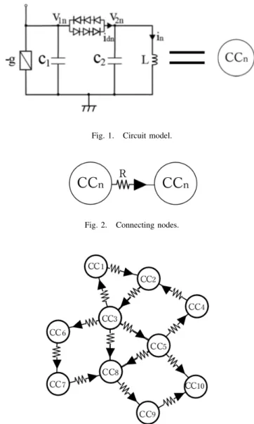
ETWORK MODELFigure 1 shows basic chaotic circuit. In this study, chaotic circuits are applied to nodes of the network. A proposed network model is shown in Fig. 2 and Fig. 3. The network consists of a chaotic circuit connected in one direction. Each node distance and coupling strength are equal.
Fig. 1. Circuit model.
Fig. 2. Connecting nodes.
Fig. 3. Network model (n=10).
- 19 -
IEEE Workshop on Nonlinear Circuit Networks December 7-8, 2018
First, the circuit equations are given as follows:
L di
ndt = v
2nC
1dv
1ndt = gv
1n− i
dn− 1 R
∑
k∈Cn
(v
1n− v
1k) C
2dv
2ndt = − i
n+ i
dn,
(1)
(n = 1, 2, 3, ..., 10),
we approximate the i − v characteristics of the nonlinear resistor consisting of the diodes,
i
dn=
G
d(v
1n− v
2n− a) (v
1n− v
2n> a) 0 ( | v
1n− v
2n| ≤ a) G
d(v
1n− v
2n+ a) (v
1n− v
2n< − a).
(2)
By using the parameters and variables as follows:
i
n=
√ C
2L ax
n, v
1n= ay
n, v
2n= az
nt = √
LC
2τ, “ · ” = d
dτ , α = C
2C
1β =
√ L C
2G
d, γ =
√ L C
2g, δ = 1 R
√ L C
2.
(3)
The normalized circuit equations are given as follows:
˙ x = z
n˙
y = αγy
n− αβf(y
n− z
n) − αδf (y
n− y
k)
˙
z = βf (y
n− z
n) − x
n.
(4)
Where the nonlinear function corresponding to the character- istics of the nonlinear resistor of the diodes and are described as follows:
f (y
n− z
n) =
y
n− z
n− 1 (y
n− z
n> 1) 0 ( | y
n− z
n| ≤ 1) y
n− z
n+ 1 (y
n− z
n< − 1).
(5)
By computer simulations, we observe the synchronization by calculating the voltage and surveying the voltage difference.
In addition, we observe the synchronization in the case where the nodes of the network model in Fig.3 are connected in the reverse direction and in the case where they are connected in both directions. We observe the difference by comparing the synchronization when the node is connected in the reverse direction and when it is connected in both directions.
III. S
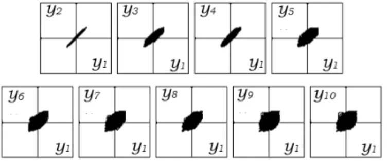
IMULATION RESULTSIn this study, we fix parameters as α = 0.5, β = 20, γ = 0.5 and δ = 0.22 on all circuits. The simulartion results are shown in Figs. 4 to 11. Figure 4 show the phase difference.
We observe in-phase state, in CC1-CC2 to CC5. However, we did not observe inphase state in CC1-CC6 to CC10.
Fig. 4. Phase difference (CC1-CC2, CC1-CC3, CC1-CC4, CC1-CC5, CC1- CC6, CC1-CC7, CC1-CC8,CC1-CC9, and CC1-CC10).δ= 0.22.
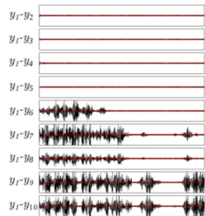
Figure 5 shows the voltage difference. We did not observe difference of voltage in CC1-CC2 to CC5. However, we observed difference of voltage in CC1-CC6 to CC10. We observed that the voltage difference is smaller in CC1-CC6 than in CC1-CC9 to CC10. We anticipate CC6 to CC8 may be synchronized as time goes on.
Fig. 5. Voltage difference(CC1-CC2, CC1-CC3, CC1-CC4, CC1-CC5, CC1- CC6, CC1-CC7, CC1-CC8,CC1-CC9, and CC1-CC10).δ= 0.22.
We observe synchronization between CC8 and other nodes.
Figures 6 show the phase difference. We observe did not ob- serve in-phase state in CC1-CC6 to CC10. We have observed that the difference between CC9 and CC10 is particularly large.
- 20 -
Fig. 6. Phase difference (CC8-CC1,CC8-CC2, CC8-CC3, CC8-CC4, CC8- CC5, CC8-CC6, CC8-CC7, CC8-CC8,CC8-CC9, and CC8-CC10).δ= 0.22.
We observed the synchronization when the nodes of the network model of Fig. 3 are connected in the reverse direction.
Figures 7 show the phase difference. We understood that CC8 is not synchronized with any nodes.
Fig. 7. Phase difference (CC8-CC1, CC8-CC2, CC8-CC3, CC8-CC4, CC8- CC5, CC8-CC6, CC8-CC7, CC8-CC8, CC8-CC9, and CC8-CC10).δ= 0.22.
We observed the synchronization when the nodes of the network model of Fig. 3 are connected in both directions.
Figures 8 show the phase difference.We observed that the phase difference is similar to the result in Fig. 6 for the network in Fig. 3.
Fig. 8. Phase difference (CC8-CC1, CC8-CC2, CC8-CC3, CC8-CC4, CC8- CC5, CC8-CC6, CC8-CC7, CC8-CC8, CC8-CC9, and CC8-CC10).δ= 0.22.
Figure 9 shows the voltage difference. We observed that CC9 and CC10 are larger in voltage difference than CC1 to CC7.
Figure 10 shows the voltage difference when the nodes of the network model of Fig. 3 are connected in both directions.
Figures 8 and Fig. 10. show that the voltage difference is smaller when connecting in both directions than in the case
Fig. 9. Voltage difference(CC8-CC1, CC8-CC2, CC8-CC3, CC8-CC4, CC8- CC5, CC8-CC6, CC8-CC7, CC8-CC8, CC8-CC9, and CC8-CC10).δ= 0.22.
where nodes are connected in the direction of Fig. 3. Moreover, Fig. 10 shows that the voltage difference from CC8 to CC10 is larger than the voltage difference between CC1 and CC2.
We understood that the magnitude of the voltage difference differs between the case of the network model of Fig. 3 and the case of connecting in the same direction of the nodes.
Fig. 10. Voltage difference(CC8-CC1, CC8-CC2, CC8-CC3, CC8-CC4, CC8- CC5, CC8-CC6, CC8-CC7, CC8-CC8, CC8-CC9, and CC8-CC10).δ= 0.22.
- 21 -
Here, we observed the phase difference when the node of the network model of Fig. 3 was connected in both directions.
Figure 11 shows the phase difference. Comparing Fig. 11 with Fig. 4, we understood that CC1 has a phase difference from CC2 to CC5. Also, we observed that the phase difference between CC9 and CC10 is larger than the phase difference from CC2 to CC8.
Fig. 11. Voltage difference(CC1-CC2, CC1-CC3, CC1-CC4, CC1-CC5, CC1- CC6, CC1-CC7, CC1-CC8, CC1-CC9, and CC1-CC10).δ= 0.22.
IV. C
ONCLUSIONSWe studied synchronization phenomena of coupled chaotic circuit with one-way coupling. Synchronization phenomena was observed certain part of the circuit with completely in- phase state. Also, we understand that the synchronization phenomenon changes greatly by changing the direction con- necting the networks. In this study, we used ten chaotic circuits. For the future works, we will use more number of chaotic circuits. Also, we will focus on other nodes and observe synchronization phenomena. By using more chaotic circuits, we expect to observe complicated phenomena such as clustering. Also, we expect to observe chaos synchronization.
Also, it is expected that differences in characteristics will be observed by changing network connection.
R
EFERENCES[1] K. Kaneko, Clustering, Coding, Switching, Hierarchical Ordering, and Control in a Network of Chaotic Elements, Physica D, vol. 41, pp.
137-172, 1990.
[2] K. Ago, Synchronization Phenomena of Coupled Chaotic Circuit Network with Bridge IEEE Workshop on Nonlinear Circuit Networks (NCN’13), pp. 27-29, Dec. 2013.
[3] K. Ago, ”Clustering of Coupled Logistic Map with Bridge” Heisei 20th Conference on Electrical Relations Association Shikoku Branch Conference Presentation paper, no. 1-23, p. 23, Sep. 2013.
[4] M. Inoue and H. Hata, Foundations and development of chaos science , 1999, pp.171199.