まえがき=地球環境保護の動きに対し,自動車の燃費向 上,CO2ガス排出量を抑制する要求が社会的に高まって いる。このためには,車体重量の低減が不可欠である一 方,衝突安全に関する法的規制が強化されており,軽量 化と安全性向上を両立させる技術開発が強化されてい る。これに対し,車体重量の約 70%を構成する鉄鋼材料 を軽量化することは有効な方法であり,超軽量鋼製車体 の 開 発 プ ロ ジ ェ ク ト で あ る ULSAB(Ultra Light Steel Auto Body)及びその次世代プロジェクトである ULSAB- AVC(ULSAB-Advanced Vehicle Concept)では,鉄鋼材 料の最適な利用による大幅な車体軽量化と衝突安全性の 両立の可能性が提示された1)〜3)。また高強度と高加工性 を兼備える新しい高強度鋼板(以下ハイテン)が開発さ れており,適用部材の拡大とともにその使用量が増大し つつある。
ハイテンを用いた衝突特性の評価については,これま でにも多くの検討がなされている4)〜6)。近年,新車開発 の期間短縮とコストダウンのため,各種シミュレーショ ンが自動車開発技術に取入れられており,衝突安全性の 向上については,車両の衝突シミュレーション技術の開 発・実用化が進んでいる。
自動車の衝突時に車体部品に作用するひずみ速度は 100 〜数 100/sec 程度といわれており,衝突シミュレーシ ョン精度の向上には,部材を構成する材料について実際 の衝突時の変形特性を正確に把握することが重要である。
本報では,ハイテンの高速変形特性を評価するための高 速引張試験方法及び構造部材として組立てられた部品の衝 突特性を評価する各種衝撃圧壊試験機について紹介する。
1.高速引張試験方法
1.1 高速引張試験
鋼板の高速引張試験方法としては,Hopkinson-Bar 法
や One-Bar 法などが一般に知られている。
当社では,鋼板の高速変形時の機械的特性の調査に,
電気油圧サーボ式の高速引張試験機を用いている。本試 験機の模式図を図 1に示す。本試験機は,試験片上部に 設置したスライダの助走距離(100mm)の間に,油圧シ リンダを所定速度まで加速したあとに引張試験を行うも のであり,ひずみ速度 0.1/sec 〜 1 000/sec の範囲で任意 のひずみ速度にて鋼板の応力−ひずみ曲線を測定するこ とが可能である。また比較的大きな試験片を使用するこ とができることが特徴である。本試験機で使用する試験 片の形状を図 2に示す。本試験機では引張速度が高速に なるとロードセルが応答しなくなり,正確な応力が測定
32 KOBE STEEL ENGINEERING REPORTS/Vol. 52 No. 3(Dec. 2002)
高強度鋼板の衝突特性と評価方法
Estimation Methods and Testing Machines for the Evaluation of Impact Deformation Properties in High-strength Steel Sheets
Reduced car body weight for fuel economy and improved impact safety are increasingly in demand in the automobile industry. High-strength steel sheets have been developed for this purpose. The amount of such steels used in the industry are on the rise. The dynamic properties of these steels were investigated to improve automobile crash precision simulation. FEM analysis show that the crush test, based on the properties of high speed tensile test, rather than that of the static speed tensile test, is able to correctly estimate the absorbed energy of the steel's collapse.
■自動車用材料特集 FEATURE : Materials for Automotive Industry
(解説)
向井陽一 Youichi Mukai
渡辺憲一 Kenichi Watanabe
鉄鋼部門・加古川製鉄所・技術研究センター
Approach (100mm)
Slider
Strain measurement
Load measurement Test piece
Load cell
(use at low-speed test) Strain gage
図 1 高速引張試験装置
Fig. 1 Schematic illustration of high-speed tensile test machine
できないという問題が生じるため,試験中の応力変化は 試験片つかみ部の表裏面に貼付けたひずみゲージで測定 している。またひずみ測定は,試験片平行部に貼付した ひずみゲージにて行った。ただし,ひずみゲージの測定 範囲(0 〜数%)以上のひずみは,ひずみゲージで測定 したひずみ速度がほぼ一定に達したあと,そのひずみ速 度が一定に保たれると推定した。
1.2 試験結果例
高速引張試験の一例として図 3・図 4に,表 1に示す 供試材A・Bをひずみ速度 0.1/sec,875/sec で試験を実 施したときの公称応力―公称ひずみ線図を示す。各鋼板 とも,高ひずみ速度域では変形応力が大きく上昇してい ることが分かる。高ひずみ速度ではノイズが混入してい るが,応力の評価は十分可能だと考えられる。
1.3 衝突シミュレーションと試験の整合性
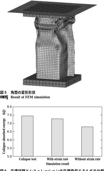
これらの引張試験の結果を用い,部材の衝撃圧壊特性
のシミュレーションを行った。さらに成形品による実圧 壊試験を行い,シミュレーション結果と比較した。部材と しては,フロントサイドメンバと呼ばれる自動車の前面 衝突時の衝撃吸収用部品を単純化した角筒モデルを用い た。板厚は 1.4mm で,70×70mm の正方形断面,軸方向 長さ 300mm の形状とした。シミュレーションは有限要素 法による,動的陽解法を用いた非線形解析にて実施した。
成形品の実圧壊試験には,自由落下式衝撃圧壊試験装置 を用いた(図 7 後述参照)。図 5にシミュレーションの 結果を示す。また図 6に試験値及び鋼板のひずみ速度依 存性を考慮した場合と考慮しない場合での,変位 100mm での吸収エネルギの計算結果を示す。これよりシミュ レーションの結果は,鋼板のひずみ速度依存性を考慮し た場合の方がより試験値に近い値を示すことが分かる。
2.各種衝突試験装置の紹介
当社では,構造部材として組立てられた部品での衝撃 圧壊特性を評価する各種衝撃圧壊試験機を有している。
以下にその設備を紹介する。
2.1 落重式衝撃圧壊試験機
図 7に試験機の模式図を示す。本試験機は自由落下式 の衝撃圧壊装置で,圧壊試験は,重さ約 200kg の落錘を 高さ 11.3m から自由落下させ,試験体を圧壊するもので
神戸製鋼技報/Vol. 52 No. 3(Dec. 2002) 33
20 BA
90
20 10
8 154 13
Strain gage (at both side) A:Strain measurement B:Load measurement R1
図 2 高速引張試験の試験片形状
Fig. 2 Schematic illustration of high-speed tensile test specimen
0.16/s 875/s 800
600
400
200
0
Nominal stress (MPa)
0 0.1 0.2
Nominal strain
0.3 0.4
図 4 公称応力ー公称ひずみ線図 (590MPa) Fig. 4 S-S curve of high-speed tensile test (590MPa)
0.16/s 875/s 800
600
400
200
0
Nominal stress (MPa)
0 0.1 0.2
Nominal strain
0.3 0.4
図 3 公称応力ー公称ひずみ線図 (440MPa) Fig. 3 S-S curve of high-speed tensile test (440MPa)
El.(%) TS (MPa)
YP (MPa) Thickness (mm)
33 448
344 1.6
440MPa (A)
29 609
323 1.4
590MPa (B)
表 1 供試材の機械的性質
Table 1 Mechanical properties of used steels
8.0 7.5 7.0 6.5 6.0 5.5 5.0
Collapse test With strain rate Simulation result
Without strain rate
Collapse absorbed energy (kJ)
図 6 圧壊試験とシミュレーションの圧壊吸収エネルギの比較 (590MPa)
Fig. 6 Comparison of collapse absorbed energy of test result and simulation (590MPa)
図 5 角筒の変形形状 Fig. 5 Result of FEM simulation
あ る。落 錘 が 試 験 体 に 衝 突 す る 速 度 は,14m/sec
(50km/h)である。本試験機は,フロントサイドメンバ と呼ばれる自動車の前面衝突時の衝撃吸収部材を模擬し た角筒成形材の圧壊試験をはじめ,ピラー類の側突試験 など各種高速圧壊試験が可能である。
2.2 振子式衝突試験機
図 8に試験機の模式図を示す。本試験機は,台車に取 付けた試験体に振子を衝突させるもので,衝突試験は重 量 約 1 500kg の 振 子 を 斜 め 上 方 に 振 上 げ,衝 突 速 度 8km/h で衝突させる。本試験機はバンパビームなどの衝 突試験に用いられる7)。
2.3 バリヤ式衝突試験機
図 9に試験機の模式図を示す。本試験機は試験体を台 車に取付け,錘の落下により台車を高速で引張り,圧力 壁に取付けられたバリヤに衝突速度 30km/h で衝突させ るものである。本試験機は大型部品で試験できることが その特徴であり,実車サイズでの衝突試験が可能である。
むすび=自動車の設計,開発工程においては,その性能 評価のためあらゆるシミュレーション技術が利用されて いる。衝突シミュレーションについては実車レベルでの
性能評価を可能にすることを最終目標とし,今後は部品,
モジュール単位でのさらなる精度向上が重要となる。こ のためには,材料の持つ変形特性のみならず,部品,モ ジュールへの製造工程で加工,熱処理などによって材料 特性がどのように変化するかを明確にし,部材としての 状態を正確に把握する必要がある。シミュレーション精 度の向上につとめ,衝突安全と軽量化を両立する材料を 提供し,地球環境を保護する社会的使命を少しでも果た すよう努力していきたい。
参 考 文 献
1 ) 栗山幸久ほか:自動車技術会 , 材料フォーラム(2002), p.16.
2 ) 吉武明英ほか:自動車技術会 , 材料フォーラム(2002), p.22.
3 ) 岩谷二郎:自動車技術会 , 材料フォーラム(2002), p.28.
4 ) 渡辺憲一ほか:CAMP-ISIJ,9(1996), p.1381.
5 ) 渡辺憲一 ほか:CAMP-ISIJ,10(1997), p.378.
6 ) 渡辺憲一ほか:自動車用材料シンポジウム資料 , 日本鉄鋼協会 自動車用材料検討部会(1997), p.73.
7 ) 石飛秀樹ほか:自動車技術会論文集,Vol.29, No.2, 9834330
(1998), p.4.
34 KOBE STEEL ENGINEERING REPORTS/Vol. 52 No. 3(Dec. 2002)
Load cell
Pipes for shock absorbed Test piece
Drop height:11.3m
Drop weight (200kg)
図 7 落重式衝撃圧壊試験機
Fig. 7 Schematic illustration of apparatus for drop test
Bumper beam Barrier
Wall
Winch Carrier
Load cell 図 9 バリヤ式衝突試験機
Fig. 9 Schematic illustration of apparatus for barrier crush test Load cell
Carrier Pendulum
Bumper beam
図 8 振子式衝突試験機
Fig. 8 Schematic illustration of apparatus for pendulum crush test