PAPER
Localization Method Using Received Signal Strength for Wireless Power Transmission of the Capsule Endoscope
Daijiro HIYOSHI†,Student Member andMasaharu TAKAHASHI†a),Fellow
SUMMARY In recent years, capsule endoscopy has attracted attention as one of the medical devices that examine internal digestive tracts with- out burdening patients. Wireless power transmission of the capsule endo- scope has been researched now, and the power transmission efficiency can be improved by knowing the capsule location. In this paper, we develop a localization method wireless power transmission. Therefore, a simple algo- rithm for using received signal strength (RSS) has been developed so that position estimation can be performed in real time, and the performance is evaluated by performing three-dimensional localization with eight receiv- ing antennas.
key words: capsule endoscope, position estimation, received signal strength, wireless power transmission
1. Introduction
In recent years, capsule endoscopes which are able to ob- serve a wider range than conventional endoscope as one of the medical devices examining the interiors of digestive tracts and without pain in examination have attracted at- tention. The capsule endoscope is a capsule type medical device having a diameter of about 16 mm and a length of 26 mm, and having an image photographing function and a wireless communication function [1]. As an examination process, the capsule is firstly taken from the mouth, moves through the GI tract by peristaltic exercise, photographs ex- amination regions, and transmits the image data to a sensor array outside the body by wireless communication.
One of the problems of capsule endoscopy is driving power source. Currently, electricity is supplied by the bat- tery built in the capsule. However there are problems such as the limit to the number of images, and the risk that the electrolyte leaked from the battery may adversely affect the human body when the capsule is clogged in the body.
In order to solve these problems, techniques for wire- less power transmission from the outside of the body have been developed. Using a sensor array that receives image data from the capsule, electric power is supplied to cap- sules by transmitting radio waves[2]. With this technol- ogy, the capsule can work in the body all the time in en- doscopy. Furthermore, the battery is unnecessary to build in the capsule, hence miniaturization can be expected. Here, since the receiving electrodes outside the body are in the form of an array, it is possible to give directionality the ra-
Manuscript received November 9, 2018.
Manuscript publicized February 18, 2019.
†The authors are with Chiba University, Chiba-shi, 263-8522 Japan.
a) E-mail: [email protected]
DOI: 10.1587/transcom.2018EBP3328
dio wave by controlling the phase [3], [4]. Therefore, in wireless power transmission, it is expected to improve the efficiency of power transmission by limiting the radio waves to a specific position. For that, it’s necessary to specify the position of the capsule endoscope. In this paper, we propose a localization method for wireless power transmission.
There are various methods of localization. The perfor- mance of Time of Arrival (TOA) technology is susceptible to the influence of bandwidth and not suitable for position estimation in the human body[5]. And the Angle of Arrival (AOA) technology is difficult to realize inside a complex hu- man body structure[6]. In Received Signal Strength (RSS) localization technology, the received signal strength of the radio frequency wireless signal is measurable at the receiver side during the routine data communication without requir- ing additional power or occupying extra bandwidth[7]. RSS localization technology is the best choice for in-body local- ization[8],[9].
In order to enable more accurate localization, various methods for the capsule endoscope have been so far pro- posed [10]–[13], [19]–[22]. However, there are problems that take a huge amount of time to localize in order to per- form complicated calculations according to the living body [14],[15]. In order to realize wireless power transmission, position information needs to be obtained during the endo- scopic examination. Therefore, shortening the calculation time is essential. Furthermore, most of these studies have developed algorithms on the assumption that radio waves are radiated from omnidirectional antennas. On the other hand, the wireless power transmission technology in these studies adopts the microwave method [16]which supplies electric power via the antenna, consideration of the directiv- ity of the antenna is required. Among the previous studies, there are no studies that are described with the antenna when transmitting and receiving, and antenna characteristic is not considered.
In the previous study, the purpose is to grasp the posi- tion of the capsule in inspection and to consider the directiv- ity of the antenna by a small amount of calculation[17]. In this paper as well, we aim to specify the position informa- tion of the capsule endoscope in real time, and localization is performed by a simple algorithm in consideration of the directivity of the antenna in the simulation.
The structure of this paper is shown below. Section 2 shows the system structure of localization and the simula- tion model created for analysis. In Sect. 3, the investigate result is shown about the parameter for localization. Fur- Copyright c2019 The Institute of Electronics, Information and Communication Engineers
2.1 Localization Method
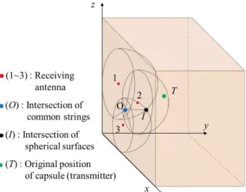
In this section, the system of localization is explained. As shown in Fig. 1, on the numerical simulation, we assumed that a radio wave was transmitted from a transmitting elec- trode installed in a human body model to a plurality of re- ceiving electrodes installed on the body surface. Biological tissue is a lossy medium, and RSS at the receiving antennas decreases depending on the thickness of the tissue. There- fore, by measuring RSS, the distance between the transmit- ting antenna and receiving antennas is able to be calculated backward. Spheres whose radii from the receiving antennas are defined as the distance obtained by back calculation are drawn. By obtaining the coordinates of the intersections of these spheres, the localization result can be calculated.
Next, the theoretical formula is shown. As shown in Fig. 1, the surface of the human body model is set as the x- z plane in the orthogonal coordinate system. The positions of the receiving antennas are grasped in advance, the loca- tion of the transmitting antenna is localized by the known receiver location. We assumed that there wereNreceiving antennas and the transmitting antenna, and define locations of then-th receiving antennaRn(n=1,· · · ,N) and the orig- inal transmitting antenna T as:
Rn=xn, yn,zn (1)
T =xt, yt,zt (2)
Hence the ideal distancednfrom then-th receiving antenna to the transmitting antenna can be represented as:
dn= q
(xt−xn)2+(yt−yn)2+(zt−zn)2 (3) When RSS of then-th antenna is defined as pn, the distance between the transmitting antenna and the receiving antenna rnis obtained by:
rn =Q(pn) (4)
as a function withpn. In this case,nequation of the sphere centered on then-th receiving antenna is given.
As shown in Fig. 1, one intersection point is obtainable from three hemispheres centered on the antennas. There- fore, by preparing three formulas, the coordinates (x, y,z) solved as a ternary simultaneous equation are the coordi- nates ofIin Fig. 1. In this study, the coordinate ofIis cal- culated as the localization result.
Since there are N receiving antennas, NC3 combina- tions for selecting three antennas are obtained in total. De- fineMas:
Fig. 1 Intersection of spheres in rectangular coordinate system.
M=NC3 (5)
Where them-th intersection locationIm(m = 1,· · ·,M) is represented as:
Im=xm, ym,zm (6)
Consequently, average ¯Imis outputted as the localization re- sult. This result is compared with the position of the trans- mitting antennaT. The distance between them is calculated and used to evaluate the performance of the algorithm.
2.2 Simulation Model
In this section, the simulation model used for numerical calculation is introduced. In electromagnetic field analy- sis with consideration of the human body, FDTD method is used as an analysis method. Next, the operating frequency is considered. The industrial, scientific and medical (ISM) radio bands are permitted to use for the medical device.
Among them, the use of 2.45 GHz band (2.4 to 2.5 GHz), 915 MHz band (902 to 928 MHz, North and South Amer- ica), and 433.92 MHz band (433.05 to 434.79 MHz, Europe and Africa) is particularly active in the microwave band. In the previous study, the electric field intensity of electromag- netic waves radiated from the power transmitting antenna was calculated by using these three frequency bands and a simple human body model. As a result, the lower the fre- quency, the smaller the attenuation of radio waves and the higher RSS [17]. Therefore, similarly to the previous re- search, 433.92 MHz, which is the lowest frequency among the above three bands, is used as the operating frequency.
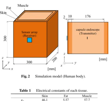
As a channel model, a simple rectangular paral- lelepiped model simulating human abdomen is used. Since duodenum contains little air, we treat small intestine as a series of masses rather than tubes, and assume that trans- mitting antenna is contained in it. The model is shown in Fig. 2. The dimension is 300×200×300 mm3to simulate the abdomen. Skin of 2 mm in thickness was placed on the
Fig. 2 Simulation model (Human body).
Table 1 Electrical constants of each tissue.
surface of the body as living tissue, and fat with a thickness of 10 mm was placed inside it. For the sake of simplicity, the inside of the human body was composed of all the mus- cles, and the size was adjusted so that the size of the entire model was 300 mm. The dielectric constant and conduc- tivity of each tissue of the human body at the frequency of 433.92 MHz used for analysis are shown in Table 1. Com- pared with this model, the actual human abdomen has a more complicated structure. Therefore, examining the prac- ticality in this model is needed. In Sect. 3.2, the result of the investigation on the influence of human body tissues on RSS is reported.
Antennas used for analysis are introduced. Origi- nally, these antennas also serve as antennas for wireless power transmission besides transmitting photographed im- age data. However, the design of antennas with the perfor- mance suitable for wireless power transmission is done by others[2],[18].
Therefore, the antennas in this study are assumed to be used for only data transmission (from the capsule to sensor array).
Propagation loss occurs when radio waves pass through living tissue. And the degree of attenuation of RSS is used to calculate the distance between the transmitting and receiv- ing antennas. Therefore, in this paper, in order to confirm the basic operation, antennas fitting within the capsule en- doscope and fitting on the human abdomen surface are used without consideration of matching.
• For the transmitting antenna, a 10 mm dipole antenna, which is small enough to install into the capsule endo- scope and has a simple structure, is used. The shape of the antenna is shown in the left part of Fig. 3.
• A spiral antenna is adopted as the receiving antenna so that it can be received irrespective of the orienta- tion of the capsule endoscope. The spiral antenna has a wide frequency band and can radiate circularly polar-
Fig. 3 Antenna models.
ized waves. On the other hand, the directivity is dis- torted. The directivity of the antenna causes degrada- tion of the localization accuracy due to reasons to be explained later. Therefore, as shown in the right part of Fig. 3, a 4-wire spiral antenna is used.
3. Calculation of Distance Between Antennas
In this section, the method of calculation of the distance be- tween antennas is explained, which is an indispensable fac- tor in the localization. In addition to the distance between the receiving and transmitting antennas, there are the factors called angle characteristics that affect RSS. Their investiga- tion and the way to process them are considered.
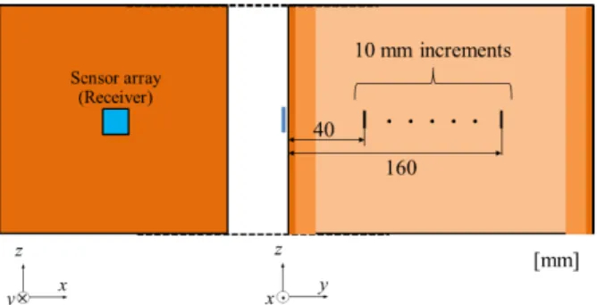
3.1 Attenuation Characteristic for Distance Calculation In order to obtain the distances rn used for localization, a function Q (pn) withpas a variable used in the formula (2) is calculated. As shown in Fig. 4, one receiving antenna is installed in the central part of the human body model, and a transmitting antenna is installed on a straight line perpendic- ularly crossing the feeding point at the center of the receiv- ing antenna. Then, in the range where the inter-antenna dis- tancednis 40 to 160 mm, the transmitting antenna is moved in intervals of 10 mm. And, as receiving radio waves trans- mitted from the transmitting antenna at each position, RSS was calculated. The simulation results are shown in Fig. 5.
For the simulation result, the approximate curve was cal- culated by the least-squares method, and this function was defined as Q (pn).
Even at the same distance RSS varies depending on the direction of the transmitting antenna. In this report, we pro- pose an algorithm in one direction, in which the dipole an- tenna is fixed vertically as a basic algorithm. We plan to solve this problem by proposing a position estimation algo- rithm using orthogonal antennas in the near future.
3.2 Influence of Human Body Tissues on RSS
This section explains the influence of human organization
Fig. 4 Calculation model on the RSS depending on antenna depth.
Fig. 5 Distance characteristic for RSS.
on RSS. There are studies reporting a detailed analysis of RSS and distance [23]. This study is described character- istics of nonmonotonicity of human tissues. In comparison with the actual human body, if the value of RSS in the pro- posed simple model is significantly different, the reliability of the result in the simple human body model is lost. There- fore, it is necessary to investigate the change of the RSS by the organization.
Studies on the effects of changes by tissues have also been conducted in previous studies[17]. We changed the thickness of fat layer and muscle layer while keeping the distance between antennas constant, and investigated the change of RSS value. The results are shown in Table 2.
The amount of change in RSS due to the presence of tissue was the largest in fat and was about 3 dB. This is considered to be a major cause of layer reflection. The change amount of RSS due to the thickness of the tissue was about 0.02 dB every 10 mm. The influence on the RSS due to the change in the presence or the thickness of the tissue absence of inter- nal tissue is minimal. From this result, we judged that even if the tissue structure of the medium between the antennas changed, there was hardly any influence on the value of RSS and it can be evaluated with a simple model.
Therefore, the human tissue with a complex structure was replaced by a simple model, and concluded that this proposed model is effective in the basically study.
Fig. 6 Two types of angle characteristics.
3.3 Angle Characteristics
In the process of collecting RSS as changing the position of the capsule endoscope by simulation, it was found that, when the capsule was installed in a portion other than the front, less RSS compared to the position in the front was obtained. This is considered to be due to the angle charac- teristics of the receiving antenna. Since the directivity exists on the antenna, ease of transmission and reception is dif- ferent for each direction in transmitting and receiving radio waves. This has an effect on RSS.
As shown in Fig. 6, there are two kinds of elements in the angle characteristic. The first is the depth direction, and the second is the surface direction. In this paper, the angle in the depth direction is referred to asθ, and the angle in the surface direction asϕ. We investigated the details of angle characteristic, and how it affected RSS, by simulation.
First, angle characteristic in the depth direction is ex- plained. Comparing the radio waves receiving from the front direction with receiving from the oblique direction, different RSSs are obtained in spite of the same distance. This is be- cause the directivity in the oblique direction is lower than that in the front. Therefore, when radio waves are received obliquely, longer distances compared to the front are calcu- lated. This causes deterioration of accuracy.
We investigated how much the angle characteristics in the depth direction affected RSS. As shown in Fig. 7, RSS calculation was carried out by moving the transmitting an- tenna so that the distance between the antennas is fixed at 80 mm on the x-yplane with thezaxis fixed, and changing θ. The calculation result is shown in Fig. 8. Compared with the position ofθ=90◦which is a position orthogonal to the receiving antenna, whenθbecomes smaller than 45◦, RSS becomes smaller and RSS attenuates by about 7 dBm at the maximum.
Fig. 7 Investigation model in depth direction.
Fig. 8 Angle characteristic in depth direction.
Fig. 9 Investigation model in the surface direction.
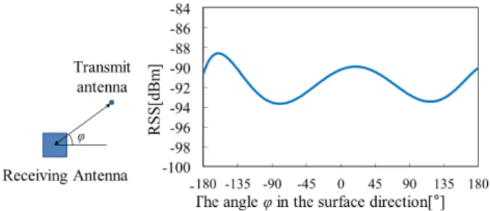
Secondly, angle characteristic in the surface direction is explained. RSS varies depending on the angle ϕ with respect to the direction of the surface of the human body model when a radio wave comes from the diagonal direc- tion. The ease of receiving radio waves varies depending on the corner of the spiral antenna, and RSS varies depending on the angle.
Figure 9 shows the model of the simulation for inves- tigation. A receiving antenna is placed at the center of the human body surface. A transmitting antenna is installed by moving so that the distance between the antennas is 110 mm on a plane 50 mm away in the depth direction. The results are shown in Fig. 10. RSS varies acceding to angle. Conse- quently, the difference of about 12 dBm between the maxi- mum value and the minimum value is confirmed.
Fig. 10 Angle characteristic in the surface direction.
In this result, note that the results in Fig. 10 are not only due to the angle characteristic in the surface direction. The influence of the angle characteristic of the transmitting an- tenna is contained in addition to one in the depth direction.
In particular, since the dipole antenna which is the trans- mitting antenna is installed in the vertical direction, RSS becomes extremely small at the position ofϕ =−90◦, 90◦ where the receiving antenna and the transmitting antenna are just above and below relationship. Hence, RSSs of these po- sitions were corrected by linear interpolation based on sur- rounding values, and the influence of the angle characteristic of the transmitting antenna was reduced.
3.4 Processing on Angle Characteristics
The angle characteristics in the surface direction have the most effect on RSS. As shown in Fig. 5, when RSS changes by 12 dBm, the distance to be calculated also changes by nearly 40 mm. This is too large error for the distance used for localization accuracy. To solve this problem, correction for angle characteristics is applied as one of the processes of localization algorithm.
A specific correction method is described. First, the processing for angle characteristics in the depth direction is described. As can be seen from Fig. 8, there is almost no change in RSS up to a certain angle. Therefore, we deal with it by reducing the number of receiving antennas used for localization. Accuracy was improved by removing such receiving antennas from localization.
Next, a correction method in the angle characteristic in the surface direction is described. Regarding the surface di- rection, correction is performed by a method of correcting the calculated distance according to the angle ϕ. Without correction,rnhas been calculated differently fromdndue to the influence of angle characteristics. Therefore, it is desir- able to calculaternas close as possible todnas possible. In this study, the method of correction using surface angle is proposed. As shown on the right side of Fig. 10, an approx- imate function corresponding to the angle is obtained and used as a correction function C (ϕ). Correction is made by multiplying the distancernby the value obtained from this function.
Algorithms using these correction functions are ex- plained in Sect. 4.
Fig. 11 Localization environment and Localization area.
4. Three Dimensional Localization
4.1 Localization Environment
The arrangement of the antenna is described when perform- ing localization in three dimensions. Figure 11 shows the installation positions of receiving antennas and the moving range of the transmitting antenna. Eight receiving anten- nas are arranged with the origin at the center of the x-z plane of this model surface. These coordinates are based on actual placement in the capsule endoscopy. PositionsRn
(n=1,· · ·,8) of each arrangement are defined as:
Rn=
(0,0) (0,80) (−60,60)
(60,60) (−80,−20)
(80,−20) (−40,−80)
(40,−80)
(n=1, . . . ,8) [mm] (7)
after defining the center of the model surface as the origin O.
The transmitting antenna is placed within the area shown in red in the figure. This area is assumed to be the range where the small intestine exists. The dimension is 200×70×160 mm3. By taking lattice points at regular in- tervals within this range, the localization of 792 points is performed.
Additionally, in this study, the continuous movement of the capsule endoscope is considered. In the actual cap- sule endoscopy, the information of the received RSS is up- dated at regular time intervals. Therefore, it is assumed that the transmission antenna moves to one adjacent lattice point for each update. As a result, it is possible to know the dis- placement distance of positions by updating. In this paper, in order to minimize the error, this distance is utilized for localization.
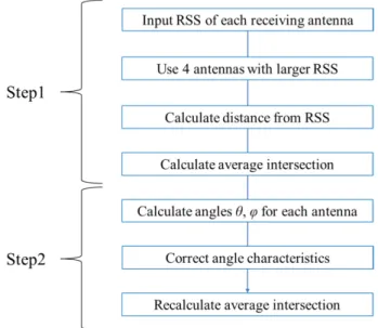
4.2 Procedure of Localization
The flow of localization of per round is shown in Fig. 12.
Fig. 12 The flow of localization per round.
Localization consists of two steps. The first is calculating temporary position for calculating the angle, and the second is to correct the distance using the obtained angle, to draw spheres again and to obtain the intersection as the localiza- tion result.
First, localization is performed using only four of the eight RSS (pn) having large values for the purpose of mini- mizing of the influence of angle characteristics in the depth direction. Let the four selected RSSs be pn0(n0=1,· · ·,4) and convert them to the distance rn0 using formula (4).
Spheres with these distance as a radius is drawn around each receiving antennas and the intersection pointsIm(m= 1,· · ·,4) of the spheres are calculated. Four intersection points is obtained from the four receiving antennas. In the first step, the average coordinate’s ¯Imare determined as the temporary position.
The second step begins by calculating the angle formed by the temporary position and each receiving antenna. An angleθn0 in the depth direction and an angleϕn0in the sur- face direction are calculated with the each receiving an- tenna. Angle correction is performed using them. First, in accordance with the combination of (rn0, θn0), an appropri- ate angle correction function C(ϕn0,rn0) is determined from among a plurality of prepared functions. Andrn00is defined as the corrected distance and given by:
r0n0 =C (ϕn0,rn0)×rn0 (8) Finally, spheres with radiirn00are drawn, and the coordinates of the intersection points Im0 are calculated. The average value ¯I0mofIm0 is output as the final positionI0.
At this time, since there is a limit of the accuracy of the correction function, there is a possibility that correction has not been appropriately applied. Therefore, if there is no way to deal with the distorted distance, the localization er- ror increases. We addressed this problem by considering the weight of intersection points. After four intersection points
are recalculated, the variance of four intersection points is calculated. A large variance suggests that the incorrect dis- tance (outliers) is included in intersections. As a method of detecting outliers, the localization result before updat- ing introduced in Sect. 4.1 is utilized. Specifically, it is as- sumed that localization has performedi-th update (i ≥ 3).
At this time, by calculating the inclination and the displace- ment distance in the traveling direction fromi-1 th andi-2 th positions, thei-th position can be estimated. As the highly reliable position, this position is compared with the four in- tersection obtained from the spheres.
At the four intersections, it is assumed that the clos- est point from this estimated position has the smallest er- ror. Therefore, the weight at the nearest position is doubled, and the weight at the furthest position is halved. Weights are set so that{w1: w2: w3: w4}={4: 2: 2: 1}in order from the nearest position, and the coordinates obtained by the weighted average are output as the localization result.
Then, the value of the variance of the four coordinates is defined as V. WhenV is extremely large or small, another weight is set. When V<0.5, it can be judged that the dis- persion of the error is small, and it is assumed that{w1: w2:
w3: w4}={1: 1: 1: 1}assuming that weighting is unnec- essary. When V>10, it can be determined that the error is large, and{w1: w2: w3: w4}={2: 1: 1: 0}is weighted as the farthest coordinates lead to the cause of the error.
In the case of update count i<3, since there is no local- ized position before updating, the weighting is determined using the distance from the temporary position. Although the error is not necessarily small as it is closer to the tem- porary position, at least since there is a tendency to move away from the temporary position when correction is failed, {w1: w2: w3: w4}={2: 2: 2: 1}, and outputs the weighted average coordinates as the localization result.
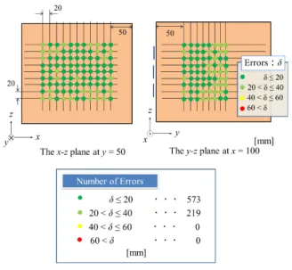
4.3 The Performance of Localization
First, we show to the time required for localization. At all 792 points, it was judged that the time from the input of RSS to the output of localized coordinate is extremely small (<0.1 s), and the real time property which is the condition for use in the wireless power transmission is sufficient. The error between the localization result and the original posi- tion was obtained. Then, colors are separately displayed in each magnitude of the error. A part of the result is shown in Fig. 13. Since it is difficult to show all the points in three dimensions, results at 50 mm from the front surface (y = 50) and at 50 mm from the right surface are displayed. As shown in the figure, an error within 40 mm was achieved at all points. Furthermore, the number of points within 20 mm of error was more than 70%. At present, the study to impart directionality by phase control in wireless power transmis- sion is still in the development stage, and there is no decision as to how much error is specifically tolerated. However, in this paper, we confirmed that the error range could be within 2 capsules (40 mm) within all area, hence we judged that the position information was able to be tracked sufficient accu-
Fig. 13 Localization result.
racy by the proposed algorithm.
5. Conclusion
In the paper, a localization method for wireless power trans- mission to the capsule endoscope is developed. Real-time localization has been required, and the position has been es- timated by a simple algorithm using RSS. We have devel- oped a method including algorithms that take antenna direc- tivity into consideration by setting transmitting and receiv- ing antennas respectively in the simulation.
Considering the angle characteristic of the antenna, in this paper, the localization was performed in two steps of calculating the temporary position and calculating the final position. By calculating the temporary position, the influ- ence of the angle characteristic of the antenna was corrected.
In addition, considering the position was updated at certain time intervals, localization was also performed using the es- timated position before updating. As a result, it was possi- ble to estimate the position within an error of 40 mm while maintaining real time property.
As a future task, it is important to consider the direc- tion of the transmitting antenna. As shown in Sect. 3.1, the RSS changes according to the direction of the transmitting antenna even at the same distance. Therefore, based on this algorithm, we aim at localization independent of orientation by combining the localization results when the transmitting antenna is horizontal and vertical.
Furthermore, we are planning to estimate the position using a model with a complex structure close to the hu- man body, using an antenna for wireless power transmis- sion. Specifically, the techniques in localization such as an- tenna characteristics are also required to practical models.
Therefore, we plan to try to adapt processing of angle char- acteristic to a complex body model. In fact, factors such as the curvature of the abdomen are left behind in the error of localization. However, as discussed in the weighting discus-
This work was supported by Chiba University SEEDS Fund (Chiba University Open Recruitment for International Ex- change Program).
This work was supported by JSPS KAKENHI Grant Number 18K04123.
References
[1] B.S. Lewis and P. Swain, “Capsule endoscopy in the evaluation of patients with suspected small intestinal bleeding: Results of a pilot study,” Gastrointest. Endosc., vol.56, no.3, pp.349–53 Sept. 2002.
[2] S. Kai and M. Takahashi, “Investigation of the wireless power trans- mission antenna for the capsular endoscope,” Proc. IEICE General Conference 2016 communication, (1), 92, March 2016.
[3] S. Tanaka, T. Mitani, and Y. Ebihara, “Simultaneous optimization of phases and amplitudes for wireless power transmission by a large- scale phased array antenna with lossy digital phase shifters,” Auto- matic Control Alliance Lecture Papers Collection, 57 (0), pp.1935–
1939, 2014.
[4] H. Kroeze, M. Kokubo, J. Kamer, A. Leeuw, M. Kikuchi, M. Hi- raoka, and J. Lagendijk, “Comparison of a capacitive and a cavity slot radiative applicator for regional hyperthermia,” Jpn. J. Hyper- thermic Oncol., vol.18, no.2, pp.75–91, 2002.
[5] J. He, Y. Geng, and K. Pahlavan, “Modeling TOA ranging error for body mounted sensors,” IEEE 23nd International Symposium on Personal, Indoor and Mobile Radio Communications, 2012.
[6] K. Pahlavan, X. Li, and J. Makela, “Indoor geolocation science and tecnology,” IEEE Commun. Soc. Mag., vol.40, no.2, pp.112–118, Feb. 2002.
[7] P. Swar, “On effect of transmit power variance on localization ac- curacy in wireless capsule endoscopy,” Wireless Commication and Networking Conference (WCNC), pp.2119–2123, 2012.
[8] J. He, Y. Geng, and K. Pahlavan, “Analysis of three-dimensional maximum likelihood algorithm for capsule endoscopy localization,”
Biomedical Engineering and Informatics (BMEI), 2012 5th Interna- tional Conference, 2012.
[9] Y. Ye, U. Khan, N. Alsindi, R. Fu, and K. Pahlavan, “On the accu- racy of RF positioning in multi-Capsule endoscopy,” IEEE 22nd In- ternational Symposium on Personal, Indoor and Mobile Radio Com- munications, 2011.
[10] K. Arshak and F. Adepoju, “Capsule tracking in the GI tract: A novel microcontroller based solution,” Proc. IEEE Sensors Applications Symposium, 2006, pp.186–191, 2006.
[11] M. Kawasaki and R. Kohno, “A TOA based positioning technipue of medical implanted devices,” Third International Symposium on Medical Information & Communication Technology, ISMICT09, Monteral, 2009.
[12] J. Bulat, K. Duda, M. Duplaga, R. Fraczek, A. Skalski, M. Socha, P. Turcza, and T. Zielinski, “Data processing tasks in wireless GI endoscopy: Image-based capsule localization and navigation with video compression,” Proc. IEEE/EMBS, 2007, pp.2815–2818, 2007.
[13] R. Kuth, J. Reinschke, and R. Rockelein, “Method for determining the position and orientation of an endoscopy capsule guided through an examination object by using a navigating magnetic field gener- ated by means of a navigation device,” Patent US2007/0 038 063, Feb. 2007.
of wireless power transmission to capsular endoscope,” Proc.
IEICE General Conference Proceedings 2014 Communication, no.1, p.167, March 2014.
[17] Y. Koike and M. Takahashi, “Capsule endoscope position estimation using received intensity,” Electronic Information and Communica- tion Society General Conference, B-1-202, March 2016.
[18] N. Hosina and M. Takahashi, “External antenna for in-body wire- less power transmission,” Electronic Information and Communica- tion Society General Conference, B-1-83, March 2018.
[19] H. Wang, Y. Zhang, X. Yu, and G. Wang, “Positioning algorithm for wireless capsule endoscopy based on RSS,” 2016 IEEE International Conference on Ubiquitous Wireless Broadband, 2016.
[20] M. Cicic, J.G. Teran, and Z. Stamenkovic, “Hardware implemen- tation of a RSS localization algorithm for wireless capsule en- doscopy,” 2015 IEEE 18th International Symposium on Design and Diagnostics of Electronic Circuits & Systems, 2015.
[21] G. Rahimi, M.R. Danaee, and S. Bayat, “A generalized total least squares algorithm for RSS-based localization with unknown path- loss model parameters,” 2016 24th Iranian Conference on Electrical Engineering, 2016.
[22] D. Li and J. Huang, “RSS based method for sensor localization with unknown transmit power and uncertainty in path loss exponent,”
2016 8th IEEE International Conference on Communication Soft- ware and Networks, 2016
[23] K. Takizawa, H. Hagiwara, and K. Hamaguchi, “Path-loss esti- mation of wireless channels in capsule endoscopy from X-ray CT images,” Proc. 33rd Annual International Conference of the IEEE EMBS, pp.2242–2245, 2011.
Daijiro Hiyoshi was born in Chiba, Japan, in 1994. He received the B.Eng. degree from Chiba university, Japan in 2017. He is currently pursuing the M.Eng. course at Chiba university, engaging in the research on localization in body area networks.
Masaharu Takahashi was born in Chiba, Japan, in December 1965. He received the B.E. degree in electrical engineering from To- hoku University, Miyagi, Japan, in 1989, and the M.E. and D.E. degrees in electrical engi- neering from the Tokyo Institute of Technology, Tokyo, Japan, in 1991 and 1994, respectively.
From 1994 to 1996, he was a Research Asso- ciate, and from 1996 to 2000, an Assistant Pro- fessor with the Musashi Institute of Technology, Tokyo, Japan. From 2000 to 2004, he was an Associate Professor with the Tokyo University of Agriculture and Technol- ogy, Tokyo, Japan. He is currently an Associate Professor with the Re- search Center for Frontier Medical Engineering, Chiba University, Chiba, Japan.