PAPER
An E ff ective Track Width with a 2D Modulation Code in Two-Dimensional Magnetic Recording (TDMR) Systems
Kotchakorn PITUSO†,Nonmember, Chanon WARISARN†a),Member, andDamrongsak TONGSOMPORN††,Nonmember
SUMMARY When the track density of two-dimensional magnetic recording (TDMR) systems is increased, intertrack interference (ITI) in- evitably grows, resulting in the extreme degradation of an overall system performance. In this work, we present coding, writing, and reading tech- niques which allow TDMR systems with multi-readers to overcome se- vere ITI. A rate-5/6 two-dimensional (2D) modulation code is adopted to protect middle-track data from ITI based on cross-track data dependence.
Since the rate-5/6 2D modulation code greatly improves the reliability of the middle-track, there is a bit-error rate gap between middle-track and sidetracks. Therefore, we propose the different track width writing tech- nique to optimize the reliability of all three data tracks. In addition, we also evaluate the TDMR system performance using an user areal density capability (UADC) as a main key parameter. Here, an areal density capa- bility (ADC) can be measured by finding the bit-error rate of the system with sweeping track and linear densities. The UADC is then obtained by removing redundancy from the ADC. Simulation results show that a sys- tem with our proposed techniques gains the UADC of about 4.66% over the conventional TDMR systems.
key words: two-dimensional magnetic recording (TDMR), 2D modulation code, intertrack interference (ITI)
1. Introduction
Two dimensional magnetic recording (TDMR)[1], [2] is a promising high-density storage technology, which is ex- pected to increase an areal density (AD) by up to 10 ter- abits per square inch (Tb/in2)[3]. This technology uses a write-narrow, read-wide technique as opposed to the write- wide, read-narrow method on a one-dimensional (1D) read channel used in perpendicular magnetic recording (PMR).
Narrow track writing operated by shingled writing which can greatly improve track per inch (TPI) gains. However, the side-reading effect of the reader is an unwanted conse- quence as it creates intertrack interference (ITI) from side- tracks which degrades overall system bit-error rate (BER) performance. Track width reduction, implemented in order to increase the AD, results to a serious increment of ITI ef- fect. Consequently, this paper focuses on the main prob- lem of TDMR - the severe ITI effect. Previously, we have proposed the use of a rate-5/6 two-dimensional (2D) mod-
Manuscript received May 28, 2018.
Manuscript revised March 7, 2019.
Manuscript publicized August 5, 2019.
†The authors are with College of Advanced Manufacturing In- novation (AMI), King Mongkut’s Institute of Technology Ladkra- bang, Bangkok 10520, Thailand.
††The author is with Seagate Technology (Thailand), Samut- prakarn 10270, Thailand.
a) E-mail: [email protected] (Corresponding author) DOI: 10.1587/transele.2018ECP5036
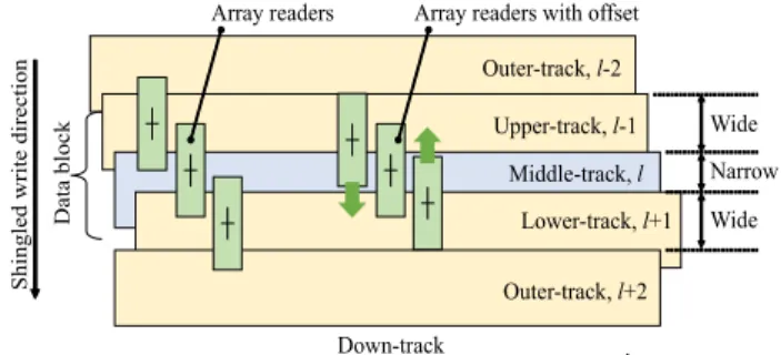
ulation code (where every 5 bits are encoded to be 6 bits of codeword[4]) to overcome the severe ITI effect. This 2D modulation code was designed based on cross-track data de- pendent readback. Data patterns such as [1−1 1]Tand [−1 1 −1]T are poor patterns, which lead to severe ITI effect, where [•]Tis transpose operator. Therefore, these two pat- terns should not be allowed to record onto a medium. How- ever, after the encoding process, these three data tracks can be written, which this coherent writing process can be per- formed effectively using an advanced Guzik spin-stand fea- ture as presented in previous research work[5]. The data bit is protected by a modulation code especially on the middle- track; thus, the middle-track can provide very reliable esti- mated data bits. Unfortunately, the data of both sidetracks still encounters with an interference from the outer-tracks as shown in Fig. 1.
Therefore, we proposed the utilization of an ITI sub- traction scheme[4]in order to increase the upper- and lower- track performances by utilizing the high-reliable feedback data from the middle-track. The optimal array reader posi- tion is also detailed in this paper. The position of upper and lower readers are moved closer to the center reader to avoid any ITI effect coming from the outer-tracks as illustrated in Fig. 1. In order to benefit from the proposed 2D modula- tion code which provides a high-reliable middle-track data sequence, we propose using an unbalanced track width tech- nique where three data tracks have unequal widths. The difference between our proposed technique and interlaced magnetic recording (IMR) is the track pitch and bit length in each track of IMR become variable[6], whereas track pitch is only one variable parameter for the proposed unbalanced track technique and the shingled manner is employed for
Fig. 1 Unbalanced track layout, shingling direction, and readers position before and after adding the head offset.
Copyright c2019 The Institute of Electronics, Information and Communication Engineers
technique in the real application.
2. Read/Write Channel Model
2.1 TDMR Channel Model
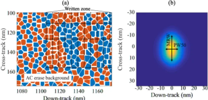
We model the granular media using a Voronoi diagram, per- fect writing, and reader sensitivity based on Yamashita’s work[7]. The parameters of granular media are defined as follows: average grain size=4.6 nm, average grain bound- ary= 0.9 nm, and grain size standard deviation=9% as displayed in Fig. 2. For perfect writing, we assume that the write field from the writer only affects to the write field cell area where the write field area is 30×30 nm2. Media grain will be magnetized if its centroid is placed within the writing area. Figure 2 (a) illustrates the zoomed-in magnetization pattern using mentioned method, where the black dash line indicates bit cell area. The writing track layout consists of three data tracks i.e., upper-, middle-, and lower-tracks [l−1, l,l+1] while two outer-tracks [l−2,l+2] that are written by using the random bits as shown in Fig. 1. The shingled- write direction is begun from the track [l−2]-th to [l+2]- th. The discrete Voronoi media is magnetized by the per- fect writing method with a random magnetized background.
The reader sensitivity is generated from the fitting form of a 2D finite element method output[7]. It results in a reader sensitivity down-track pulse width at half-maximum (PW50) of 11.28 nm, and a cross-track magnetic read width at half- maximum (MRW) of 18.44 nm as shown in Fig. 2 (b). Three readers are used to read simultaneously with perfect timing compensation. Generally, readers are positioned at the cen- ter of each data track. However, we propose to move the upper and lower readers closer to the middle-track to avoid the ITI effect from the outer-tracks as depicted in Fig. 1.
The TDMR system diagram with the rate-5/6 2D mod- ulation code and ITI subtraction scheme can be shown in
Fig. 2 (a) Bit cell area of magnetization pattern written by random data on the media modeled by Voronoi model. (b) Reader sensitivity function.
ble of a waveform signal to noise ratio method, and the sig- nal power is then calculated[8]. An additive white Gaussian noise (AWGN), nl(t) is generated for electronic and time random noises. Here the signal to time random noise ra- tio is in the range of 20-25 dBs. The readback waveform can be obtained by combining readback signals with AWGN noises, i.e.,rl(t)=vl(t)+nl(t) as shown in Fig. 3. However, there is a slight difference with the conventional TDMR sys- tem, on the write channel, an user sequenceuk ∈ {±1}of length 12,240 bits is split into three sequences
ak,l
∈ {±1} with a length of 4080 bits. Then, the sequences
ak,l will be perfectly written onto a granular medium as described above which they do not need to be encoded before writ- ing process for the conventional TDMR system. On the read channel, the readback waveforms, rl−1(t), rl(t), and, rl+1(t) are filtered using a low pass filter and sampled into discrete time sequences. The readback samples
rk,l
are then equalized by 2D finite impulse response (FIR) equaliz- ers, which are designed based on a minimum mean-squared error approach with a fixed 3×3 2D generalized partial re- sponse (GPR) target[9],[10]. The 2D GPR target coeffi- cients can be obtained from the reader sensitivity by sam- pling the reader sensitivity at the center of the bit cell area at center bit and its 8 neighboring bits. Then, the equalized samples
sk,l
are sent to a modified 2D soft output Viterbi algorithm (SOVA)[11], which exchanges the soft informa- tion among each track withNSOVA=3 iterations.
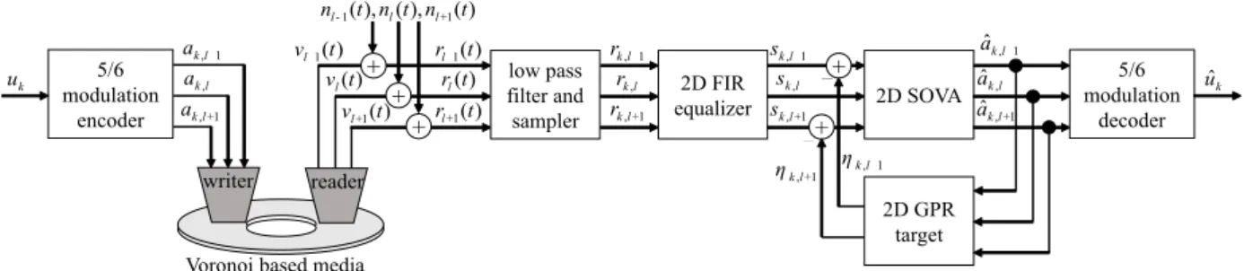
2.2 Rate-5/6 2D Modulation Code and ITI Subtraction The system diagram of the proposed techniques includes the rate-5/6 2D modulation coding, and an ITI subtraction scheme is shown in Fig. 3. The user data sequenceuk∈ {±1}
of length 10,200 bits is encoded by the rate-5/6 modula- tion code[4] that results in 3 sequences
ak,l ∈ {±1}with a length of 4080 bits. The rate-5/6 2D modulation coding scheme, designed based on cross-track ITI avoidance, re- sults in the middle-track will encounter a lower ITI effect because destructive ITI patterns such as [1−1 1]Tand [−1 1
−1]T are never recorded onto the medium[4]. As shown in Fig. 4, the middle-track BER of the coded systems can pro- vide a significant improvement when the width of all three tracks are equal. At a linear density of 3386 kBPI, con- sidering at BER =−2 decades, track density of the coded system can be increased by about 180 kTPI over a conven- tional TDMR system. However, the coded system cannot improve sidetrack performance as shown in Fig. 5. This is due to the fact that the coded system is only designed to pro- tect the ITI effect on the middle-track while the sidetracks
Fig. 3 Block diagram of the TDMR system with the rate-5/6 2D modulation code, and the ITI sub- traction scheme.
Fig. 4 Middle-track BER performance versus the kTPI of various sys- tems. Bit length is 7.5 nm (3386 kBPI).
Fig. 5 Average sidetrack (upper- and lower-tracks) BER performance versus the kTPI of various systems. Bit length is 7.5 nm (3386 kBPI).
still encounter with the interference from the outer-tracks.
Consequently, an ITI subtraction scheme was presented to improve sidetrack performance.
The idea of ITI subtraction is to utilize the middle- track data sequence to produce the remaining sidetrack ITI sequences before subtracting both upper- and lower-tracks as described in[4]. To achieve this, we first assume that
the lower-track is being considered by giving thel-th=0.
The estimated coded sequences of the middle- and upper- tracks, i.e., ˆak,0 and ˆak,−1, are fedback and convoluted with the 2D target to generate the remaining ITI sequence of the lower-track,ηk,1. The remaining ITI sequence is then sub- tracted from the noiseless data sequence of the lower-track that comes out of a recording 2D channel,sk,1. Note that the zeroes sequence will be also used to generate the remain- ing ITI sequence. For this paper, a 2D target matrix,Has a symmetric matrix with the size 3×3 was considered and can be defined as follows;
H=
⎡⎢⎢⎢⎢⎢
⎢⎢⎣
h−1,−1h−1,0h−1,1 h0,−1 h0,0 h0,1 h1,−1 h1,0 h1,1
⎤⎥⎥⎥⎥⎥
⎥⎥⎦=
⎡⎢⎢⎢⎢⎢
⎢⎢⎣ α β α δ 1 δ α β α
⎤⎥⎥⎥⎥⎥
⎥⎥⎦, (1)
where,αrepresents the ITI and ISI coefficients andδandβ are the ISI and ITI coefficients, respectively. The noiseless data sequence of the lower-track,sk,1can then be defined as follows;
sk,1=1
n=−11
m=−1hn,mak−n,1−m
=αak+1,2+βak,2+αak−1,2+ δak+1,1+ak,1+δak−1,1+ αak+1,0+βak,0+αak−1,0,
(2)
where,ak,2is the data of the outer-track that directly affects to the lower-track performance. However, the way to miti- gate this ITI effect will be described in Sect. 3.2. The esti- mated remaining ITI sequence of the lower-track can then be produced using the following equation:
ηk,1=1
n=−11
m=−1hn,maˆk−n,1−m
= δˆak+1,−1+aˆk,−1+δˆaxk−1,−1+
αˆak+1,0+βˆak,0+αˆak−1,0. (3) As mentioned above, the estimated recorded sequence of the middle-track can provide the high-reliable data.
Therefore, we may assume that the last line of Eq. (2) is equal to the final three terms of Eq. (3). Consequently, we can use this data to produce the new equalized sequence of the lower-track with its ITI effect already subtracted using sk,1 −ηk,1. It is important to note that this subtraction pro- cess is operated just one time iteration and the symmetry 2D targets are employed for all three tracks. Then, this new equalized sequence is re-sent to modified 2D SOVA. This ITI subtraction process can be applied with the upper-track
−2 decades, track density can be increased of about 80 kTPI over a traditional coded system. Moreover, we also pro- pose to move upper and lower readers to avoid outer-track reading. Using an optimal offset value by 10% of sidetrack width as demonstrated in[4], the BER of sidetracks is dra- matically improved with track density gains of more than 130 and 200 kTPI over the codeded with ITI subtraction and conventional TDMR systems, respectively. However, we found that the middle-track BER performance (Fig. 4) is slightly better than the average sidetrack BER performance (Fig. 5) when compared with the coded TDMR system that performed together with ITI subtraction scheme and moving upper and lower readers position. To improve this gap per- formance; therefore, the use of an unbalanced track width technique is then proposed.
3. Optimization of the Unbalanced Track Width Set- ting
3.1 User Areal Density Metric
An areal density capability (ADC) is one of the main param- eters that is used to evaluate the performance of magnetic recording systems[12]. The ADC test is a simple test per- formed that measures variable bit aspect ratio (BAR)[13].
During this test, the bit length and track width were swept across the upper-, middle-, and lower-tracks. For each sweep testing, the multiple data tracks are written on me- dia with a certain linear density and squeezing-track width.
Then, the readers read the media before sending readback signals to the read channel for data detection. Usually, there are many detection targets. Bit length and track width are swept until there is no erroneous bit in many data sectors after a low-density parity-check (LDPC) is performed using an iterative decoder[12]. To reduce simulation time, many research works have assumed that the BER of around−1.5 to−2 decades at the SOVA detector output is adequate for LDPC. It can correct the codewords perfectly, eliminating errors within full iterations[14],[15].
Therefore, for this paper, we used a BER target of−2 decades as well as the BER target that was proposed by Sea- gate[15]. Thus, a BER=−2 decades line can be obtained during the sweeping of a bit length and track width. The bits per inch (BPI) and TPI are picked up from the BER =−2 decades line so that its bit length and track width provide the maximum production of BPI and TPI. Eventually, this maximum AD is calculated by BPI×TPI which is defined as ADC. While, BAR can be also calculated from BAR= track width/bit length. However, the ADC of the coded sys-
Width
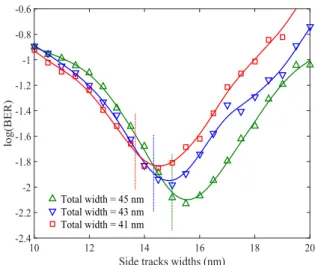
Since the middle-track BER can be improved by using the rate-5/6 2D modulation code. However, sidetracks are still weak against outer-tracks ITI. Besides the presentation of 10% reader offset, we also propose to reduce the middle- track width and enlarge sidetrack widths to improve side- track performances. Here, we can find the optimal width by measuring overall BER versus the change of sidetrack width. Figure 6 shows the overall BER as a function of various sidetrack widths for 3 total widths. The green up- pointing triangles represent the BER bathtub of an unbal- anced track width system where the total width of three tracks is 45 nm i.e., [upper: middle: lower]=[15:15:15] nm.
The green, vertical line located at 15 nm indicates that the upper-, middle-, and lower-track widths are equal to 15 nm.
It is clear that the peak of the bathtub is located on the right of the balanced track lines. Therefore, it is possible to set the track width both sidetracks to be 15.5 nm, while the middle- track width should be reduced to be 14 nm to get the best performance for a total width of 45 nm i.e., [upper: mid- dle: lower]=[15.5:14:15.5] nm, (1693 kTPI). Similarly, the other total widths also have their bathtub peak on the right side of their balanced points, which implies that we can also increase track density by reducing the total width and writ- ing the unbalanced tracks.
Since the track sizes are different, the ADC evaluation of unbalanced track recording is not the same as balanced track recording. Here, each total width needs to be verified
Fig. 6 BER bathtub as a function of sidetrack width with various total widths. Vertical dash lines indicate the location where three data track widths are equal. Note that the bit length is 7 nm (3628 kBPI).
Fig. 7 Minimum BER from the bathtub of the different total track widths of various bit length values.
in terms of its performance for various middle- and side- track widths. To do so, the peak of each bathtub needs to be plotted for various linear densities as shown in Fig. 7.
The average track density can be picked up at BER = −2 decades and analyzed using a plot on a BPI-TPI plane. This then allows us to get the ADC evaluation.
3.3 Areal Density Evaluation of Unbalanced Track Width As mentioned in the previous section, the ADC can be de- fined as a line of BER=−2 decades on the BPI-TPI plane.
To do so, in a balanced TDMR system, the linear and track densities are varied in ranges of 2400 - 4000 kBPI and 1100 - 2100 kTPI, respectively. Each BPI and TPI value was set for the writing process. The data bits were then generated randomly and fed to the read/write channel with the rate- 5/6 2D modulation code and the ITI subtraction scheme as depicted in Fig. 3.
Consequently, the read channel outputs the estimated bits, and BER can be calculated. For an unbalanced track system, a BER = −2 decades line can be specified from bathtub peak at various average track and linear densities.
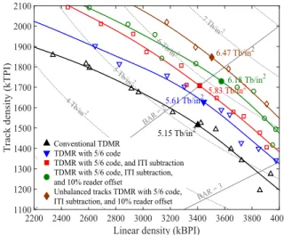
Figure 8 shows BER=−2 decades lines for various TDMR systems. The results show that the conventional TDMR provides the ADC=5.15 Tb/in2 at BAR=2.24 while the TDMR combined with the rate-5/6 2D modulation code can improve ADC=5.61 Tb/in2at BAR=2.11. However, since the coded systems have to add a redundant bit every 5 bits, the UADC becomes 4.67 Tb/in2. For the TDMR with the rate-5/6 2D modulation code and ITI subtraction technique, the system gains TPI but loses small BPI, and yields the ADC=5.83 Tb/in2(UADC=4.85 Tb/in2) at BAR=2. The TDMR with a rate-5/6 2D modulation code, ITI subtraction technique, and 10% offset reader can provide the ADC of 6.18 Tb/in2 (UADC=5.15 Tb/in2). Finally, with proposed unbalanced track writing, ADC is improved to 6.47 Tb/in2 (UADC=5.39 Tb/in2) at BAR=1.9.
As expected, BPI gain is small while TPI gain in-
Fig. 8 BER = −2 decades lines for various systems. The solid large marks show the ADC from the fitted lines.
creases dramatically because all of the proposed techniques are designed to cope with severe ITI effects. Especially at lower BAR, the increment of BER=−2 decades location in BPI-TPI plane is larger than higher BAR. The interfer- ence sources in lower BAR mostly come from ITI and it can be dealt by using our proposed techniques. However, reducing the bit length is very hard to do because it is lim- ited by grain size. Therefore, BER=−2 decades location in BPI-TPI plane at higher BAR cannot be improved as much as lower BAR. Although the TDMR system with the rate-5/6 2D modulation code and ITI subtraction has higher ADC compared with the conventional TDMR system, but the UADC is significant lower due to the rate loss. These results reveal that the narrowing width of middle-track and the rate-loss of the rate-5/6 2D modulation code become a trade-offto get higher UADC. To overcome the UADC of the conventional TDMR system, all techniques need to be integrated together. Thus, the unbalanced tracks TDMR sys- tem with the rate-5/6 modulation code performed together the ITI subtraction scheme and 10% reader offset can offer the performance gain of about 4.66% over the conventional TDMR system (UADC=ADC=5.15 Tb/in2).
4. Conclusion
We considered an user areal density capability (UADC) metrics of various two-dimensional magnetic recording (TDMR) systems using a variable bit aspect ratio technique.
The TDMR system with a rate-5/6 2D modulation code, in- tertrack interference (ITI) subtraction scheme, and off-track reading yields the best bit-error rate (BER) performance us- ing the proposed effective track width with the middle-track narrower than upper- and lower-tracks. The proposed tech- niques can improve the UADC of about 4.66% over a con- ventional TDMR, which mostly gains in track density.
Acknowledgments
This work was partially supported by Thailand Research
[2] A.R. Krishnan, R. Radhakrishnan, B. Vasic, A. Kavcic, W. Ryan, and F. Erden, “2-D magnetic recording: read channel modeling and detection,” IEEE Trans. Magn., vol.45, no.10, pp.3830–3836, Oct.
2009.
[3] R. Wood, M. Williams, A. Kavcic, and J. Miles, “The feasibility of magnetic recording at 10 terabits per square inch on conventional media,” IEEE Trans. Magn., vol.45, no.2, pp.917–923, Feb. 2009.
[4] K. Pituso, C. Warisarn, and D. Tongsomporn, “A soft-5/6 mod- ulation code with iterative ITI subtraction scheme in multireader TDMR systems,” IEEE Trans. Magn., vol.53, no.11, art ID.
3000904, Nov. 2017.
[5] A.M. Taratorin, M. Nikiforov, A. Shteyn, R. Shi, and M. Alex, “2-D visualization in magnetic recording,” IEEE Trans. Magn., vol.54, no.2, art ID. 3000408, Feb. 2018.
[6] K. Gao, “Architecture for hard disk drives,” IEEE Magn. Lett., vol.9, art ID. 4501705, Jan. 2018.
[7] M. Yamashita, H. Osawa, Y. Okamoto, Y. Nakamura, Y. Suzuki, K.
Miura, and H. Muraoka, “Read/write channel modeling and two-di- mensional neural network equalization for two-dimensional mag- netic recording,” IEEE Trans. Magn., vol.47, no.10, pp.3558–3561, Oct. 2011.
[8] S. Hernandez, P.-L. Lu, S. Granz, P. Krivosik, P.-W. Huang, W.
Eppler, T. Rausch, and E. Gage, “Using ensemble waveform anal- ysis to compare heat assisted magnetic recording characteristics of modeled and measured signals,” IEEE Trans. Magn., vol.53, no.2, art ID. 3000406, Feb. 2017.
[9] P. Kovintavewat, A. Arrayangkool, and C. Warisarn, “A rate-8/9 2-D modulation code for bit-patterned media recording,” IEEE Trans.
Magn., vol.50, no.11, art ID. 3101204, Nov. 2014.
[10] S. Nabavi and B.V.K.V. Kumar, “Two-dimensional generalized par- tial response equalizer for bit-patterned media,” in Proc. of ICC, pp.6249–6254, June 2007.
[11] C. Warisarn, T. Losuwan, P. Supnithi, and P. Kovintavewat, “An iterative inter-track interference mitigation method for two-dimen- sional magnetic recording systems,” J. Appl. Phys., vol.115, no.17, p.17B732, 2014.
[12] S.D. Granz, T. Ngo, T. Rausch, R. Brockie, R. Wood, G. Bertero, and E.C. Gage, “Definition of an areal density metric for mag- netic recording systems,” IEEE Trans. Magn., vol.53, no.2, art ID.
3100104, Feb. 2017.
[13] S. Granz, W. Zhu, E.C.S. Seng, U.H. Kan, C. Rea, G. Ju, J.-U.
Thiele, T. Rausch, and E.C. Gage, “Heat-assisted interlaced mag- netic recording,” IEEE Trans. Magn., vol.54, no.2, art ID. 3100504, Feb. 2018.
[14] E. Hwang, J. Park, R. Rauschmayer, and B. Wilson, “Interlaced magnetic recording,” IEEE Trans. Magn., vol.53, no.4, art ID.
3101407, April 2017.
[15] S. Hernandez, S. Granz, P. Krivosik, P. Huang, W. Eppler, T. Rausch, and E. Gage, “Data rate effects on transition and remanence noise in a modeled heat-assisted magnetic recording system,” IEEE Trans.
Magn., vol.53, no.11, art ID. 8205104, Nov. 2017.
Bangkok, Thailand. His researches are in the areas of communications and signal processing for magnetic recording systems.
Chanon Warisarn received the B. Eng.
(1st Hon.) in Electronics Engineering Technol- ogy from King Mongkuts Institute of Technol- ogy North Bangkok (KMITNB), Thailand in 2006, the Ph.D. degree in Electrical Engineer- ing from King Mongkut’s Institute of Technol- ogy Ladkrabang (KMITL), Bangkok, Thailand in 2011. He currently works at the College of Advanced Manufacturing Innovation (AMI), KMITL. His current research interests are in the areas of communications and signal processing for data storage systems.
Damrongsak Tongsomporn was born in Nakhon Si Thammarat province, Thailand.
He received the B. Eng. (honor) in Electron- ics Engineering from King Mongkuts Institute of Technology Ladkrabang in 2000, M. Eng./D.
Eng. in Microelectronics from Asian Institute of Technology in 2002 and 2008, respectively. He joined Seagate Technology (Thailand) in 2007 and he is currently a senior R&D manager at Magnetic Recording Subsystem Lab. Before Seagate, he served the Royal Thai Army as a missile technician during 1994–1999. In year 2000 he joined ReadRite (Thailand) as a test engineer working for dynamic electrical test of mag- netic recording head. During 2003 to 2005, he worked for Western Digital (Bang Pa-In) as a senior engineer in the area of quasi-static test.