九州大学学術情報リポジトリ
Kyushu University Institutional Repository
強制対流条件下における人体周りの熱・物質輸送
李, 丛
https://doi.org/10.15017/1398413
出版情報:Kyushu University, 2013, 博士(工学), 課程博士 バージョン:
権利関係:Fulltext available.
HEAT AND MASS TRANSFER FROM HUMAN BODY SURFACE IN FORCED CONVECTIVE FLOW
Ph.D. Thesis
By
LI CONG
Kyushu University
Department of Energy and Environmental Engineering Interdisciplinary Graduate School of Engineering Sciences
September 2013
This thesis is submitted for the degree of Doctor of Engineering at the Department of Energy and Environmental Engineering, Kyushu University, Japan. Defended publicly at Kyushu University August 10, 2013.
Supervisor:
Kazuhide Ito, Associate Professor, Kyushu University, Japan
Adjudication Committee:
Kazuhide Ito, Associate Professor, Kyushu University, Japan Tetsuo Hayashi, Professor, Kyushu University, Japan
Shinsuke Kato, Professor, the University of Tokyo, Japan Yasunori Akashi, Professor, the University of Tokyo, Japan
Table of Contents
T ABLE OF C ONTENTS
ABSTRACT ... V ACKNOWLEDGEMENT ... VII
CHAPTER 1.INTRODUCTION ... 1
1.1 A Look at the Research on Micro-climate around Human Body ... 3
1.2 Convective Heat and Mass Transfer of Human Body ... 5
1.3 Objective of This Research—People Exposes to Forced Convective Flow ... 9
1.4 Outline of Thesis ... 11
CHAPTER 2.MODELING OF TURBULENT FLOW AND HEAT TRANSFER ... 15
2.1 Reynolds-averaged Navier-Stokes Equation ... 18
2.2 Two-equation RANS Model ... 22
2.2.1 Standard k-ɛ model ... 22
2.2.2 Low Reynolds types k-ɛ model ... 23
2.2.3 SST k-ω model ... 26
2.2.4 V2f model ... 27
2.3 Large Eddy Simulation ... 30
2.3.1 Overview ... 30
2.3.2 Filetered function and sub-grid modeling ... 31
2.3.3 Inlet and wall boundary conditions for les model... 36
2.4 Simulation Methodology ... 38
2.4.1 FVM discretisation method ... 38
2.4.2 Solution algorithms ... 40
2.4.3 Boundary conditions ... 41
CHAPTER 3.ESTIMATION OF CONVECTIVE HEAT TRANSFER AROUND HUMAN BODY BY WIND TUNNEL EXPERIMENT ... 47
3.1 Introduction ... 49
3.2 Experiment Setup ... 49
3.2.1 Wind tunnel space... 49
3.2.2 Experiment thermal manikin ... 53
3.3 Calculation Process for the Convective Heat Transfer Coefficient ... 55
3.4 Results and Discussion ... 57
3.5 Conclusion ... 63
CHAPTER 4.CFD SIMULATION OF CONVECTIVE HEAT TRANSFER FOR HUMAN BODY SEGMENT ... 65
4.1 Numerical Simulation according to the Wind Tunnel Experiment ... 67
4.1.1 Virtual manikin ... 67
4.1.2 Radiation heat flux analysis... 69
Table of Contents
4.1.3 Numerical and boundary conditions ... 74
4.1.4 Results and discussion ... 75
4.2 Prediction Accuracy ... 81
4.2.1 Comparison to previously reported results ... 81
4.2.2 Predictive equation of convective heat transfer coefficient ... 82
4.3 Numerical Simulation Focused on Extremely Strong Convective Flow ... 84
4.3.1 Analytical domain and cases ... 84
4.3.2 Flow field and temperature distribution around virtual manikin ... 85
4.3.3 Results and discussion ... 86
4.4 Conclusion ... 93
CHAPTER 5.DEVELOPMENT AND PERFORMANCE EVALUATION OF PROTOTYPE MODEL OF WIND DECONTAMINATION SYSTEM ... 95
5.1 Introduction ... 97
5.2 Prototype Model of Wind Decontamination System... 98
5.3 Performance Evaluation of WDCS—Liquid-phase Experiment ... 100
5.3.1 Experimental subject and targeted contaminant ... 100
5.3.2 Experiment procedure and cases ... 101
5.3.3 Decontamination efficiency of liquid-phase contaminant ... 102
5.4 Performance evaluation of WDCS—Gas-phase Experiment ... 105
5.4.1 Experimental subject ... 105
5.4.2 Experiment condtion and procedure ... 106
5.4.3 Decontamination efficiency of gas-phase experiment ... 108
5.5 Approximation of Moisture Transfer Coefficient ... 109
5.5.1 Numerical calculation of simultaneous heat and moisture transfer ... 109
5.5.2 Mass transfer coefficient ... 115
5.6 CFD Simulation for Estimating the Contribution Ratio of Each Supply Inlet in WDCS Prototype Model ... 117
5.6.1 SVE4 definition ... 117
5.6.2 Contribution ratio of each supply inlet of WDCS ... 118
5.6.3 Results and discussion ... 119
5.7 Conclusion ... 124
CHAPTER 6.MODELING OF PARTICLE DETACHMENT FROM HUMAN BODY SURFACE ...127
6.1 Introduction ... 129
6.2 Nano-scale Aerosol Deposition Model for CFD in Indoor Environmental Analysis ... 130
6.2.1 Introduction ... 130
6.2.2 Previsous studies of deposition models ... 130
6.2.3 Proposing a deposion model that considers surface aspect ... 131
6.2.4 Sensitivity analysis ... 136
6.2.5 Results ... 138
6.2.6 Discussion ... 140
6.3 Literature Review: Particle Resuspension/Detachment in Indoor Environment ... 142
6.4 Euler-Lagrangian Particle Tracking Method ... 144
6.5 Modeling of Particle Detachment ... 146
Table of Contents
6.5.1 Physical forces act on particle ... 146
6.5.2 Numerical modeling by using les model ... 149
6.6 Results and Discussion ... 152
6.7 Conclusion ... 163
CHAPTER 7.CONCLUSIONS... 165
REFERENCEES... 171
APPENDICES ... 179
LIST OF PUBLISHED PAPERS ... 187
Abstract
ABSTRACT
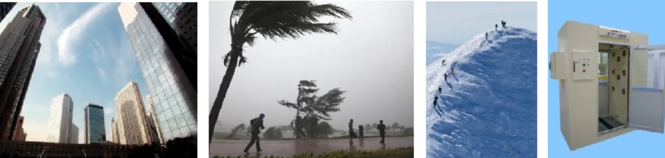
Occasionally, a human body will expose to a strong forced convective flow, e.g., walking in the vicinity of the tall buildings where a strong wind blowing against, involving in a severe tropical storm or typhoon, climbing the mountain in a strong wind, or experiencing purging treatment in an industrial air-shower alike system which is used to remove the contaminant from human body.
From the viewpoint of ensuring the safety of people and reducing the effects of disasters, control of strong winds is crucial in the design of residential spaces.
Considering the physiology of human beings, forced strong convective airflow would be a dominant parameter of heat loss from the human body. On the other hand, convective heat transfer coefficient as a critical physical parameter of scalar transfer would help approximate the mass transfer of the human body based on the heat and mass transfer analogy. Hence, research on convective heat transfer would indicate the efficiency of desorption or detachment of contaminant on the human body surface. In this scenario, understanding of heat and mass transfer phenomenon around human body would contribute to the development of thermal sensation/comfort model in indoor environment design and would also contribute to the decontamination system in industrial application.
As aforementioned, however, most of these studies focus on the air movement around the human body under relatively low velocity (several meters per second or less, maximum approximately 5m/s), with the goal of understanding and improving the indoor air quality (IAQ) or thermal sensation/comfort especially in context of indoor environmental. Thermal comfort in outdoor environment is a topic that, until recently, has received little attention. There is no reports for targeting high velocity region, i.e.
higher than 7 m/s.
The purpose of this study is to better understand heat and mass transfer around the
Abstract
human body especially in forced convective flow. Towards this end, this thesis mainly consists of three parts: the first part describes fundamental investigation of heat and mass transfer coefficient around human body by using wind tunnel experiment and computational fluid dynamics(CFD) technique. Based on fundamental investigation and approximation, the second part introduced a wind decontamination system developed for industrial application of forced convective flow against the human body. The third part is an ongoing work which focuses on the particulate-phase contaminant mass transfer around the human body. At current stage, preliminary work on modeling of particle detachment from human body surface was conducted.
Acknowledgement
ACKNOWLEDGEMENT
The research work presented in this Ph.D. thesis has been carried out at Hayashi and Ito laboratory, Department of Energy and Environmental Engineering, Kyushu University from October 2010 to August 2013.
I express my sincere gratitude to my supervisor, Professor Kazuhide Ito, who accepted my application to study in his laboratory in 2010, and gave me opportunity to purse my Ph.D. study. He gave me valuable guidance, suggestions, encouragement, and provided a lot of opportunities to experience many things and exercise myself during the past three years. Without his help, this dissertation would not have been possible.
I am deeply grateful to Professor Tetsuo Hayashi, who is smart, humorous, gentle, considerable, fatherly, and always be so kind to me. Thanks so much for his guidance and invaluable instructions which I highly appreciated.
I wish to acknowledge my thanks to Assistant Professor Koji Nomura, Eunsu Lim, who gave me much help in my experiment set up and also daily life. Thank my seniors, Dr. S.
Onishi and Dr. Phuong for their warm help, nice talk and suggestions during the days of hardships.
I want to thank Professor R. Youshie, Department of Architecture, Tokyo Polytechnic University. My experiment conducted in Wind Engineering Research Center of Tokyo Polytechnic University received generous support from Professor R. Youshie.
Special thanks to Paionia Furyoyuhi Co., Ltd., who provided the prototype model of Wind Decontamination System.
Sincerely thanks to China Scholarship Council, who sponsored my Ph. D course in Japan. Without her financial support, I could not devoted to myself into research heart and soul.
Acknowledgement
Thank my colleagues, present and past, of Hayashi and Ito laboratory, for their kind help and friendship in various aspects of my life in Kyushu University of Japan.
Finally, I would like to appreciate to my beloved family, my parents, my sister, my boyfriend. Sincere thanks for your generous, thoughtful kindness and supportive at every stage of my life and any of my decision.
Li Cong August 2013
Chapter 1. Introduction
CHAPTER 1
INTRODUCTION
Chapter 1. Introduction
Chapter 1
INTRODUCTION
1.1 A
LOOK AT THE RESEARCH ON MICRO-CLIMATE AROUND HUMAN BODYWith the improvement of the economic development and people's living standards, humans have moved more of their activities indoors. We now typically spend 90% of our lives indoors. Care must be taken that the ventilation strategy is efficient, and that thermal comfort and indoor air quality are satisfactory throughout the occupied zone.
In recent years, the research subject of the indoor air environment has drawn much attention, such as focusing on the energy conservation on premise of the indoor air quality (IAQ), and the influence of chemical or biological contaminants released or distributed in indoor environment, e.g., VOCs(Volatile Organic Compounds), Particulate Matter, etc.
Humans plays an central role in indoor environmental issues. Hence in studying the indoor environments, the most important goal is to clarify the relationship between the human body and surrounding environments.
In this respect, Thermal Manikin was introduced in indoor research. Thermal manikin, as its name suggests, is a heated dummy has a realistically shaped with the human body.
It has become one of the useful tools with which to directly measure the heat exchange or heat transfer between the humans and their thermal environment. In fact, the thermal manikin was originally developed to measure the thermal insulation of clothing (Winslow and Herrington, 1949).
Chapter 1. Introduction
Tanabe. et al., (1994) reported a method for measuring a non-uniform thermal environments by employing a skin surface-temperature-controlled thermal manikin named Anne (see Figure 1-1). The heating elements used for manikin Anne is placed at the outer of surface of the manikin. This kind of heating system would produce a relatively small time constant on the manikin(less than 5mins). That paper described the configuration of the thermal manikin and further control logic of such surface temperature of the thermal manikin in detail, and the theory is still widely used up to now.
Figure 1-1. Picture of thermal manikin Anne.
Nowadays, with the improvement of the technology and increasingly interest and concern about the human body's health in indoor environment, various kinds of manikins are developed and designed with various kinds of purposes, for example, the thermal manikin with respirator system that consists of inhalation and exhalation, thermal manikin specially adapted to cars, etc. (PT TEKNIK, http://pt-teknik.dk). A lot of work conducted by using a thermal manikin has been done in Denmark(Alborg University and Technology University of Denmark). As early as 1997, BROHUS(1997) has reported the measurement of personal exposure using a breathing thermal manikin.
Around the topic of microclimate of the human body, a growing number of studies have described the estimation of the interaction between the human body surface and the atmospheric air under various kinds of conditions, based on theoretical or experimental studies. Although experimental research using thermal manikins would provide valuable information, e.g., airflow velocities, temperature, pollutant
Chapter 1. Introduction
concentration, etc., however, some other more detailed information, such as the flow parameters generated in the vicinity of the human body, coupled analysis of convective heat transfer and radiative heat transfer, is difficult to be obtained by experiment. In the last few years, CFD technology has been processing and popularly used in indoor research area. It has capacity to provide a high resolution pictures of air flow and temperature throughout the space and to analysis more detail information about the micro-climate around the human body. Meanwhile, computational virtual manikin were proposed in conducting CFD simulation as well. These development and advantages make it possible to using CFD to analysis human-microclimate issues with various kinds of intentions.
In a number of studies, Murakami and Kato's group has conducted much CFD study on analyzing and designing the microclimate surrounding the human body. One can referred to his review paper(Murakami, 2004). Other research related to CFD simulation on human body including simulation on people's respiration and exposure (Gao and Niu, 2006; Ge, Li, et al., 2013), person's clothing and thermal comfort, convective heat and radiation transfer, etc. (Murakami, Kato, et al., 2000; Kurazumi, Tadahiro et al., 2008).
1.2 C
ONVECTIVE HEAT AND MASS TRANSFER OF HUMAN BODY The key research topic of energy exchange between the human body and its thermal environment has been investigated and quantified by diverse disciplines in consideration of human thermal tolerance and comfort, including physiology, engineering, architecture, psychology and meteorology. A goal for comfort and heat stress research is a comprehensive model of human thermal regulation and prediction of thermal comfort by numerical algorithms. Such kind of model need precise information about spatial and temporal change of conditions around the human body. The completion of such work partly depends on obtaining empirical verified and applicable heat transfer coefficients at individual segments. In this point of view, convective heat transfer coefficient has been well investigated and reported in the last few years.de Dear. et al. (1997) reported the sensible heat transfer between the human body and ambient environment by setting up a thermal manikin in a wind tunnel across a range of
Chapter 1. Introduction
wind speeds from still air to 5m/s. Selected velocity tests represented the typical atmospheric conditions of both indoors and outdoors. It is estimated that the radiative heat transfer coefficient and convective heat transfer coefficient for the whole body were 4.5 W/m2/K and 3.3-3.4 W/m2/K respectively, under the conditions of air speed less than 1m/s and a skin-to-air temperature gradient of 12K. Similar experimental works on convective and radiative heat transfer refer to Seppanen et al. (1972) and other researchers(Ichihara et al., 1997; Watanabe et al., 2008; Kuwabara et al., 2001). They conducted experiment by varying the body postures, wind directions, wind velocities, etc.
Lee et al. (1991) investigated the impact of velocity and turbulence intensity on convective heat transfer coefficient distributions around a thermal manikin. Their results showed that the convective heat transfer coefficient increased significantly with the turbulence intensity in case of the forced convection flow over 0.3 m/s.
Plenty of work conducted computational fluid dynamics (CFD) and a computer simulated person (CSP)/virtual manikin to obtain more detailed non-uniformity information that cannot be easily obtained experimentally. Murakami and Kato's group (Murakami, Kato et al., 1997) proposed a two-dimensional prototype of computational virtual manikin and analyzed the convective heat transfer characteristics of the manikin.
The mean convective heat transfer coefficient is calculated to be 3.9 W/m2/K in a stagnant air, which agrees well with previous experiment results.
Sørensen and Voigt (2003) made an improvement on a computational manikin. That virtual manikin is an exact copy from a experimental thermal manikin, enabling similar set-ups during calculation and experiments. Thus the feature of this study enables a high degree of resolutions to analysis the flow field and heat transfer around the human body.
Natural convective heat transfer around the computational virtual manikin was considered in his research and the calculations were compared to the measurement by PIV(Particle Image Velocity) method. Another point I'd like to note is the computational grid used in his CFD simulation was a composited mesh that constructed as two separate regions: a small volume with fine mesh near the surface of the virtual manikin, and relative coarse mesh designed for the outer region.
Chapter 1. Introduction
On the other hand, to provide an applicable information of convective heat transfer coefficient in the outdoor context, Ono et al.(2006) conducted experiment work in a wind tunnel under a maximum velocity of 4m/s and carried out corresponding numerical simulation. In addition, his research proposed a predictive formula for the mean convective heat transfer coefficient of the human body.
Compared with heat transfer, mass transfer process is a more complicated physical procedure, since 'Mass' transportation depends on different substances that we can classify 'Mass' under three types: liquid-phase, gas-phase, and particulate-phase substances. Different substances have different transport mechanism.
Most of the research on liquid-phase mass transfer specially focused on the moisture transfer. Take the example of the research on the buildings and building materials, the indoor relative humidity should be kept within a given range to assure the comfort of the occupants. In this case the moisture exchange between the indoor air and porous materials inside the building plays an important role(Steeman, Janssens et al., 2009).
The interests of the study of the moisture related damage in a building usually lies in a hygrothermal behavior of materials since heat and moisture happened simultaneously.
Using the heat and mass transfer analogy to convert the heat transfer coefficient to mass transfer coefficient is one of the approaches to calculate the local transfer coefficients.
Another common phenomena is Drying, a fundamental problem involving simultaneous heat and mass transfer under transient conditions. Kaya, Aydin et. al., (2006) analyzed the heat and mass transfer of a moist object in a two-dimensional domain. They considered the spatial variables of convective heat transfer coefficients and calculated the spatial variables of convective mass transfer coefficients rather assuming constant convective heat and mass transfer coefficients.
Of interest here is focusing on the heat and mass transfer closely correlated to the human body. Evaluation of the clothing system and its relation to the human comfort is an important topic in the clothing research, such as in the design of the functional clothing for extremely cold and hot conditions. Many studies of modeling the heat and moisture transport through the clothing or fabric media to the ambient environment
Chapter 1. Introduction
were reported(Conrad, 2009, Michal. Sobera, 2003, . Ghali, Ghaddar, et al., 2002, Das, 2007, Fan and Wen, 2002). Ghali et al. and Kyughoon et al. developed mathematical model for the heat and moisture transfer from the skin surface to the ambient air through fabric medias. The model of Ghali et. al. imitated the walking conditions of human activity, and intends to be allowed to integrate into other models of walking humans to predict fabric response of heat and moisture transport.
Above studies focused on liquid-phase mass transfer, especially moisture transfer.
Gas-phase mass transfer is another important research area. Individual gas transfer may not reflect the reality, gas-phase mass transfer always accompanies with the phenomena of sorption or emission, likes a sub-process. A majority of research discussed the VOC emissions from the building materials (Sparks, Tichenor et al., 1996, Yang, Chen, 2001, Haghihat, Huang, 2003). During the emission or sorption procedure, the gas-phase convective mass transfer is essentially considered.
In view of the difficulty in controlling the gas-phase substance, CFD simulation is an trend in case of different venues. With respect to the indoor pollutant and air quality of residents, Hyun and Kleinstreuer (2001) conducted transient numerical simulation with gaseous pollutant transport in a personal exposure environment. The purpose of this research is to examine the effect of transient breathing on trace gas concentrations and uptake concentrations.
Of concern on airborne particulate-phase transport in indoor environments, the dominant parameter of heat and mass transfer is not the temperature gradient, water vapor gradient or concentration gradient, but a dynamic disturbance, such as the progress of particle resuspension (particles previously deposited onto surfaces), particle detachment, and so on. This process may be a key part of an important exposure pathway for allergens(Nazaroff, 2004). Ordinary indoor activities such as walking or housekeeping would cause particle resuspension. The consequence is increasing the occupational exposure to particulate matter. Take the ventilation duct as an example, the resuspended particles of the ventilation duct flow back into the air would decrease the indoor air quality and damage to people's health. Only a few studies have investigated the particle resuspension.
Chapter 1. Introduction
Continue with previous study which mainly focused on liquid-phase and gas-phase heat and mass transfer, in the third part of this thesis, we take interest in the mass transfer mechanism of particulate phase, intending to modeling the particulate-phase contaminant detached from human body surface.
1.3 O
BJECTIVE OF THIS RESEARCH—PEOPLE EXPOSES TO FORCED CONVECTIVE FLOWOccasionally, a human body will expose to a strong forced convective flow, e.g., walking in the vicinity of tall buildings that a strong wind blowing against, involving in a severe tropical storm or typhoon, climbing the mountain in a strong wind, or experiencing purging treatment in an industrial air-shower alike system which generates forced convective flow to remove the adsorbed or deposited contaminant (as depicted in Figure 1-2).
Figure 1-2. People exposes to strong forced convective flow
From the viewpoint of ensuring the safety of people and reducing the effects of disasters, control of strong winds is crucial in the design of residential spaces.
Considering the physiology of human beings, forced convective airflow would be a dominant parameter of heat loss from the human body. On the other hand, convective heat transfer coefficient as a critical physical parameter of scalar transfer would help approximate the mass transfer of the human body based on the heat and mass transfer analogy. Hence, research on convective heat transfer would indicate the efficiency of desorption or detachment of contaminant from human body surface. In this scenario, understanding of heat and mass transfer phenomenon around the human body will contribute to the development of thermal sensation/comfort model in indoor environment design and also the decontamination system in industrial application.
Chapter 1. Introduction
As aforementioned, however, most of previous studies focus on the air movement around the human body under relatively low velocity (several meters per second or less, maximum approximately 5m/s), with the goal of understanding and improving the indoor air quality (IAQ) or the thermal sensation/comfort especially in context of indoor environment. Thermal comfort in outdoor environment is a topic that, until recently, has received little attention. There is no reports for targeting a high velocity region, i.e.
higher than 7 m/s.
The purpose of this research is to better understand the heat and mass transfer around the human body especially in forced convective flow. Towards this end, this thesis mainly consists of three parts: Fundamentals part describes fundamental investigation of heat and mass transfer coefficient around human body by using wind tunnel experiment and computational fluid dynamics(CFD) technique. Based on fundamental investigation and approximation, the second part, Application, proposed a wind decontamination system(WDCS) developed for industrial application which employs forced convective flow against the human body. The third part, Particle Detachment, is an ongoing work that focuses on the particulate-phase contaminant mass transfer around the human body. At current stage, preliminary study on modeling of particle detachment from human body surface was conducted.
Chapter 1. Introduction
1.4 O
UTLINE OF THESISThe outline of this study is diagrammed in Figure 1-3.
Figure 1-3. Research content
In Chapter 1, "Introduction", firstly it gave an general look on the researches of Micro-climate around the human body. Around this topic, convective heat and mass transfer of the human body was brought up and drawn attention. Better understanding heat and mass transfer of human body would provide empirical and applicable information for the research topics such as thermal comfort, heat exchange between the human body and ambient environment, and also contaminant desorption from the skin surfaces. Related literatures are reviewed. The objective of this research is to better understand the heat and mass transfer of the human body especially in case of the human body exposes to forced convective flow. Outline of this thesis is given.
In Chapter 2, "Modeling of Turbulent Flow and Heat Transfer", CFD simulation
Chapter 1. Introduction
methodology of modeling of turbulent flow and heat transfer are summarized.
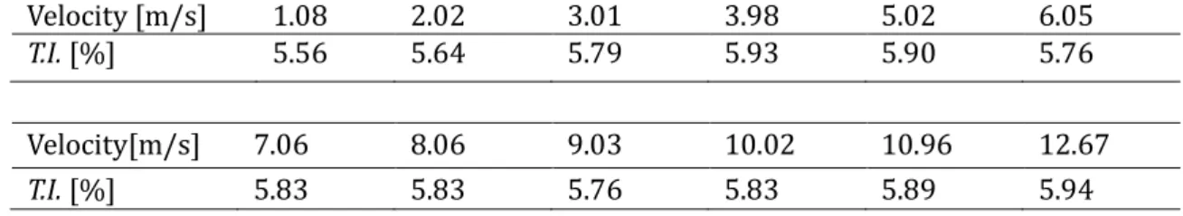
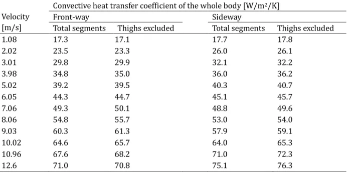
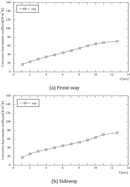
In Chapter 3, "Estimation of Convective Heat Transfer around Human Body by Wind Tunnel Experiment", the wind tunnel experiment and thermal manikin setup were introduced. This experiment covered a large range of velocities, from 1.08m/s to a maximum of 12.67m/s. By obtaining the total heat supply and temperature measurement of body surface and ambient air, convective heat transfer coefficients were calculated.
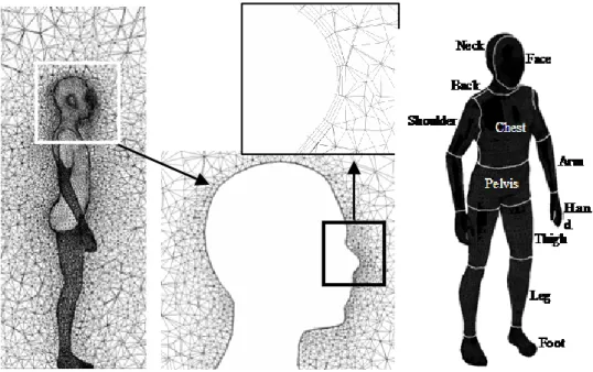
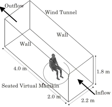
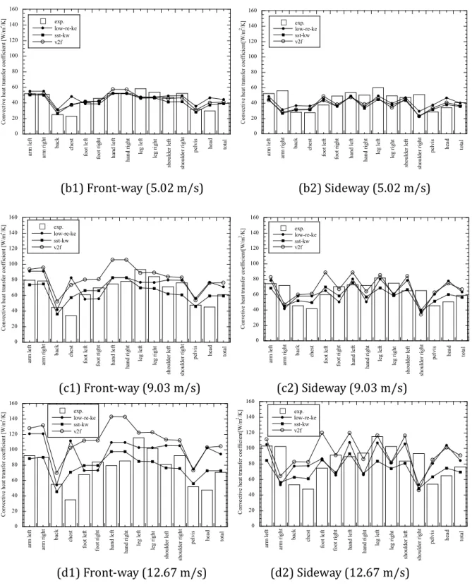
In Chapter 4, "CFD Simulation of Convective Heat Transfer for Human Body segment", CFD simulation according to the wind tunnel experiment was conducted. A virtual manikin represented true human body was integrated into the numerical analysis. Three kinds turbulent models which are popularly used in the engineering are selected: SST k-ω, Low Re k-ɛ, and v2f model. Comparing to the experimental results, the predictive accuracy of each turbulence model was validated. It is observed that SST k-ω model performed better than Low Re k-ɛ model and v2f model, especially for high velocity cases.
Predictive formulas of convective heat transfer coefficient of the human body under large range of velocities were then developed as a function of inlet velocity. The last part of this chapter showed the estimation results of CFD simulation on extremely high velocity cases, i.e., 15~25m/s.
In Chapter 5, "Development and Performance Evaluation of Prototype Model of Wind Decontamination System", based on the preliminary work, a new Wind Decontamination System(WDCS) was developed. It applies forced convective flow to increase the mass transfer, thereby enhancing the desorption/detachment of contaminants from the body surface. Fundamental liquid-phase(pure liquid water) and gas-phase(SF6) experiments were conducted to evaluate the performance of WDCS. For further exploration, the contribution ratio of each air supply openings of WDCS was also discussed.
In Chapter 6, "Modeling of Particle Detachment from Human Body Surface", the particulate-phase resuspension phenomena which would move a fraction of deposited material back into the atmosphere was considered. Differ from liquid-phase and gas-phase contaminant, the dominant parameter of heat and mass transfer due to the
Chapter 1. Introduction
temperature gradient or concentration gradient, detachment of particulate-phase contaminant from surface is a dynamic progress and it has many effective parameters.
For the purpose of studying the effect of the particle detachment from the surfaces when people exposed in to hazardous materials, we mainly considered those particles lifted into air flow excluding the sliding and rolling off ones. CFD modeling of particle detachment from human body surface takes term of lift-off mode was conducted by employing LES in combing with Euler-Lagrangian particle tracking method.
In Chapter 7, "Conclusions", major findings were summarized.
Chapter 2. Modeling of Turbulent Flow and Heat Transfer
CHAPTER 2
MODELING OF TURBULENT FLOW AND HEAT
TRANSFER
Chapter 2. Modeling of Turbulent Flow and Heat Transfer
Chapter 2
MODELING OF TURBULENT FLOW AND HEAT TRANSFER
In numerical simulation, only motions of scales larger than the mesh size can be resolved. Turbulence flows are associated with a multitude of scales in time and space.
The dynamics of eddies in turbulence is characterized by an energy transportation from large eddies to small ones, and then through the action of viscosity, into heat. This suggests that the lower bound to the length scale in turbulence is the influence of viscosity, i.e., the dissipative scales. The upper bound is determined by the geometric size of the flow field domain. Take the turbulence of ventilation flow as an example, the smallest length scale may be of an order of 0.1mm, while the largest scale is the dimension of the ventilated room that is usually several meters.
In theory it is possible to resolve the whole spectrum of turbulent scales using an approach that is known as direct numerical solution (DNS). DNS is a available to solve the non-linear differential governing equations and allows full resolution down to the smallest scales. That is free of modeling approximations. Note that the span of length scales grows with the macro scale Reynolds number, Re, to a power of 3/4. This means that the number of grid points required for a DNS in three dimensions is of an order of Re9/4. It is clearly that with an increasing Reynolds number in the range of engineering applications, direct computation for turbulent flow thus requires a prohibitively increasing computer power. Although DNS is able to provide detailed information on turbulent structure at low Reynolds numbers flow for validating and improving turbulence models, it is not yet ready as a tool for solving practical flow problems.
Chapter 2. Modeling of Turbulent Flow and Heat Transfer
Attempts made to avoid full resolution of the span of length scales as in DNS bring in another approach, that is, Large Eddy Simulation(LES). The basic philosophy in LES is to filter out the small scales so as to make a relatively coarse mesh usable for the numerical resolution of the large scales. The motion of small scale, on the other hand, is presumed to be more homogeneous and universal in nature and thus more amenable and requiring of fewer adjustments for successful modeling. To distinguish small-scale and large-scale eddies, a filtering process is carried out on the governing equation of large-scale motions.
The consequence of the filtering operation is that the small-scale eddies are filtered out and the governing equations becomes only for the evolution of large-scale eddies motions. Nevertheless, the effect of unresolved small scales on resolved large scales needs to be accounted for by modeling.
LES is similar to DNS in that it provides three-dimensional, time-dependent solutions of the Navier-Stokes equations. The large scales are, in principle, required to contain kinetic energy as much as possible in order to let the small scales to obey inertial subrange dynamics. Therefore LES still requires fairly fine meshes. In many engineering applications, it is more interested in detecting mean flow properties rather than detailed fluctuating motions. However, even with DNS and LES, the most meaningful and practical result usually lies in the mean field and is obtained by time-averaging the instantaneous quantities. Use of statistical approaches is thus another desirable alternative in which the Reynolds-averaged Navier-Stokes(RANS) equations, which describe the evolution of the mean quantities, are solved. In RANS approaches, all stochastic turbulent fluctuations are averaged out through a time-averaging process. This averaging process, however, introduces unknown correlations. To close the governing equation system, these unknowns must be modeled.
The following sections introduced the evolution progress of RANS model and LES method, including the basic knowledge of CFD simulation and its solution methodology.
2.1 R
EYNOLDS-AVERAGED NAVIER-STOKES EQUATIONThe governing equations for the motion of a continuous phase express the conservation of the mass, momentum and energy. For the incompressible flow field, the
Chapter 2. Modeling of Turbulent Flow and Heat Transfer
Navier-Stokes equations in Cartesian coordinates are:
0
i i
x
u (2-1)
ij i
j i j
i j
i S f
x x u p
x u t
u
1 (2 )
)
(
(2-2)
S
x T Tu x
x t T
j j
j j
( ) ( ) (2-3)
Equations (2-1)—(2-3) represent the mass conservation, momentum conservation, and energy conservation, respectively. fi is the external force, e.g., the buoyancy force,
S is a source term in the energy equation. Sij is the strain rate tensor, expressed as:
) 2(
1
i j j ij i
x u x S u
(2-4)
The Reynolds-averaging approach is to decompose the instantaneous variable in the Navier-Stokes equation into the mean and fluctuating components:
' i i
i u u
u (2-5) where ui is the mean velocity and ui'is the fluctuating velocity (i = 1,2,3).
Likewise, other instantaneous variables(e.g., pressure, energy, concentration, etc. ) could be decomposed as:
' i i
i
(2-6) t dt
t
t
i
t10 0 1
1
(2-7)
Using above decomposition for Equations(2-1)—(2-3), the mass conservation keeps the same form, the momentum and energy governing equations read:
i j i ij j i j
i j
i S u u f
x x u p
x u t
u
1 (2 )
)
( ' '
(2-8)
u T S
x T Tu x
x t T
j j j j
j
( ) ( ' ') (2-9)
Chapter 2. Modeling of Turbulent Flow and Heat Transfer
Equations (2-8)—(2-9) are called Reynolds-Averaged Navier-Stokes(RANS) equations.
They have the same form as the instantaneous Navier-Stokes equations, with ensemble-averaged value. Resultant equation shows that additional terms appeared: the turbulent Reynolds stress ui'uj', and turbulent heat flux ui'T'. They represent the transport of momentum and heat due to fluctuating motions.
New unknown correlations of various kinds of variables arise in the RANS equations.
A further possible derivation of transport equations for all these unknown correlations is possible and would include additional, higher order correlations. This consequently leads to the closure problem. To obtain a closed set of equations, many researchers worked on this issue.
As the modeling directly formulates the turbulent Reynolds stresses and heat fluxes is in terms of known mean flow properties, the eddy viscosity/diffusivity concept has been used for a wide class of turbulence models in practical use. In analogy to the viscous stresses in laminar flows, Boussinesq suggested that the turbulent stresses are proportional to the mean velocity gradients. This approximation reads:
ij i
j j t i j i
ij k
x u x u u
u
3
) 2
' (
'
(2-10)
where t is the viscosity, k is the turbulent kinetic energy, defined as ' ' 2 1
i iu u k , which is in an additional term to give the model a correct trace. And
ijis the so-called Kronecker deltaj i
j i if if
ij
, 0
,
1 (2-11)
This term is often absorbed in the pressure-gradient term in numerical computations.
In a similar way, the turbulent heat flux can be formulated through the eddy diffusivity concept, i.e.,:
j t t j t i
ij x
T x
T T u
h
' ' (2-12) where t is the eddy diffusivity. In writing Equations (2-10) and (2-11), the ratio of
Chapter 2. Modeling of Turbulent Flow and Heat Transfer
the eddy viscosity and diffusivity is used to define the turbulent Prandtl number,
t t t
t
Pr , whose value is often assumed to be constant in the eddy-viscosity -based models.
Based on the eddy viscosity/diffusivity concept, the modeling turns out to be a task of determining tor t. Unlike the molecular viscosity, turbulent eddy viscosity is a property of the flow, but not of the fluid. It is thus a function of time and spaces.
Moreover, one may note that the eddy viscosity is essentially an isotropic quantity, that is, it is equal in all directions. The eddy viscosity is constructed to be a product of turbulent velocity scale( Vt ) and length scale( Lt ), i.e., t VtLt. Depending on how these scales are prescribed, several types of eddy-viscosity-based turbulence closures have been developed and used in engineering practice.
The simplest type is Zero-equation models, where the eddy viscosity is either assumed to be a constant value, or is directly related to the local mean velocity gradient and the flow geometry. For example, using the famous Mixing Length hypothesis, one may write the eddy viscosity in a generalized form:
21
] ) [(
j i i
j j m i
t x
u x u x l u
(2-13) where lm is the mixing length whose distribution over the flow field is prescribed by means of empirical formulations, detailed information could be referred to Rodi(1980).
In One-equation models, the eddy viscosity is described by t k . This would yield:
t
t c kL
(2-14) where c is the model constant, k is the turbulent kinetic energy. A transport equation for k is then required. The unknown correlations are further modeled in terms of t and Lt. Formulating the turbulent length scale Lt is an critical work to close the equation system. In most of One-equation models, Lt is determined by trial-and-error, empirical relations. As in the Zero-equation models, using the mixingChapter 2. Modeling of Turbulent Flow and Heat Transfer
length hypothesis, the prescription of the length scale has proven to be a difficult matter in both the physics and also numerical simulation.
Spalart-Allmaras model is a relatively simple one-equation model and it embodies a relatively new class of one-equation models in which it is not necessary to calculate a length scale related to the local shear layer thickness. The transported variable in the Spalart-Allmaras model is , which is identical to the turbulent kinematic viscosity except in the near-wall region. Detailed information on transport equations refers to Spalart and Allmaras(1992). It should be noted that the original form of Spalart-Allmaras model is effectively a low-Reynolds-number model, requiring the viscosity-affected region of the boundary layer to be properly resolved. In FLUENT software, however, the Spalart-Allmaras model has been implemented to use wall functions when the mesh resolution is not sufficiently fine.
2.2 T
WO-EQUATION RANS MODELBoussinesq approach is applied into One-equation model such as Spalart-Allmaras model and two-equation k-ɛ model. In turbulent models that employ the Boussinesq approach, the central issue is how the eddy viscosity in computed. The simplest
"complete models" of turbulence are the two-equation models in which the solution of two separate transport equations allows the turbulent viscosity and length scale to be independently determined. Among the eddy-viscosity-based models, two-equation models have had the most applications in the engineering, such as k-ɛ,k-ω and RSM models. The following sections will describe some representative two equation RANS models.
2.2.1 STANDARD k-ɛ MODEL
The standard k-ɛ model makes use of the eddy viscosity concept and relates the eddy viscosity to the turbulent kinetic energy, k, and turbulent dissipation, ɛ (
k23 /Lt).The eddy viscosity is defined as
t c k2 (2-15)
Chapter 2. Modeling of Turbulent Flow and Heat Transfer
The modeled k transport equation takes the form:
k M b
k j k t j
i
i G G Y S
x k x
x ku t
k
[( ) ] (2-16)
Similarly, the modeled transport equation of ɛ is read as:
S
C k G C k G
x C x
x u
t j k b
t j
i
i
2
2 3
1 ( )
] )
[( (2-17)
In these equations, Gk represents the generation of turbulence kinetic energy due to the mean velocity gradients; Gb is the generation of turbulence kinetic energy due to buoyancy. Ym represents the contribution of the fluctuating dilatation in compressible turbulence to the overall dissipation rate. C1, C2, C3are constants. k and are the turbulent Prandtl number for k and ɛ. Sk and Se are user-defined source terms.
S2
Gk t (2-18) whereS is the modulus of the mean rate-of-strain tensor, defined as
S 2SijSij (2-19) The constants have the following default values:
c
=0.09, c1 1.44, c2 1.92, k 1.0, 1.3The standard k-ɛ model is a semi-empirical model based on model of the transport equation for the turbulent kinetic energy k and its dissipation rate ɛ. As the strength and weakness of the standard k-ɛ model have become known, improvements have been made to model to improve its performance. Two of these variants are available in ANASYS FLUENT: RNG k-ɛ model and the realizable k-ɛ model. Detailed derivations for the closure equations are provided in Fluent manual.
2.2.2 LOW REYNOLDS TYPES k-ɛ MODEL
Generally a high-Reynolds-number model cannot be integrated over the whole flow domain for the wall-bounded turbulent flow. This would cause problems when employing the turbulent models into the enclosed space, especially the indoor environment, such as, the ventilation room, the microclimate surrounding the human body, etc..
Chapter 2. Modeling of Turbulent Flow and Heat Transfer
Take the numerical simulation in the ventilation room for example, the flow field is not only in near-wall regions but also in regions far away from the wall surfaces. In the near-wall regions, it is showed that all energetic large eddies reduce to dissipative Kolmogorov eddies and, consequently, all the near-wall flow properties, such as friction velocity and the mean strain rate, are characterized by Kolmogorov micorscales. There must be some modifications for the near-wall surfaces and their ambient flow field. That is to say, the modifications should consider the high-Reynolds flow and low-Re flow in the enclosed indoor environment spaces. Viscous modifications to high-Re number models are thus necessary to make the models have an appropriate to response to flows in which the effect of the molecular viscosity becomes comparable to that of the eddy viscosity.
Numerous experiments have shown that the near-wall region can be largely subdivided into three layers. In the innermost layer, called "viscous sublayer", the flow is almost laminar, and the molecular viscosity plays a dominate role in the momentum and heat and mass transfer. In the outer layer, called "fully-turbulent layer", turbulence plays a major role. For the interim region between the viscous sublayer and the fully developed layer, it is called buffer region, where the molecular and the turbulence are equally important. Figure 2-1 illustrates the subdivisions of the near-wall region.
Figure 2-1. Subdivision of the Near-Wall Region
Chapter 2. Modeling of Turbulent Flow and Heat Transfer
One of the solutions is applying the wall-function, which can conjunct high-Re models to the flow of the near-wall condition. It would be described in Section 2.3.3.
Note that the origin of the wall functions is related to the local equilibrium and uniform wall shear stress assumptions and the so-called log-law of the wall. As a consequence, the usage for the complex flow becomes questionable, e.g., for flows with separation. The wall function method may be inappropriate in turbulent boundary layers at low Reynolds numbers, since the prediction of frictional drag for external flows, or pressure drop for internal flows, depends on fidelity of local wall shear stress predictions, and also the pressure drag for bluff bodies is dependent upon extent of separation. Furthermore, the thermal performance of heat exchangers is determined by wall heat transfer whose prediction depends on the near-wall effects. Using the wall functions into boundary conditions in numerical simulations, the drawbacks would give incorrect expressions at the grid points of the near wall where wall functions are used.
To find an alternative approach instead of using the wall-function approach which would cause some drawbacks, different modeling methods have been developed to account for the near-wall turbulence behaviors. Such models can be directly integrated towards the wall surface and are able to simulate near-wall viscous effects. Many researchers proposed some methods on modeling the near-wall treatment. The most popular approach is to modify the two-equation model through low-Reynolds formulation, i.e., damping functions, so that the viscous effects can be appropriately reflected in the turbulent transport equations as being integrated towards a wall.
The main objective in low-Reynolds types k-ɛ (hereafter LRN) model is to add a proper damping function to re-model various terms in the turbulent transport equations so that they are able to respond reasonably in physics to near-wall turbulence properties. The basic considerations in LRN formulation is to reduce the near-wall eddy viscosity in a proper way so as to emphasize the near-wall effects towards the wall surface. That can be achieved by adjustments in the near-wall turbulent kinetic energy and dissipation rate by, e.g., damping or reinforcing the production and dissipation of the transport equations.
Chapter 2. Modeling of Turbulent Flow and Heat Transfer
To reduce the near-wall eddy viscosity, t is modified by multiplying a function f that can connect the flow ensures viscous stress dominate at low Reynolds numbers, i.e., in the near wall region. In a LRN k-ɛ model, t is defined as
t Cf k2 (2-23) The equations of k and of LRN model are given as
j t j
j i i
j j
t i i
i x
k x
x U x U x U x
U k t
k (2-24)
f k x C
x x U x U x
U C k
U x
t j
t j
j i i
j j
t i i
i
2 2 1
(2-25)
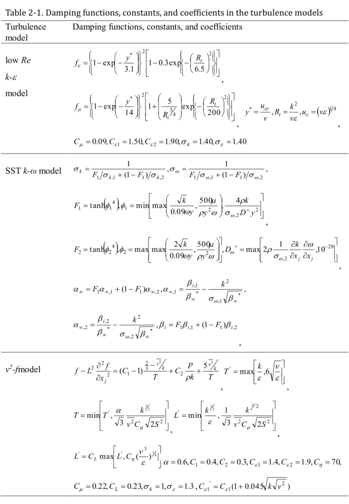
The models constants and the damping functions of LRN k-ɛ model can be found in
Table 2-1. In addition, it should be noted that since the LRN k-ɛ model is to resolve the viscosity-affected region with a mesh to the wall including the viscous sublayer, the first grid should be fine enough.
2.2.3 SST k-ω MODEL
The shear-stress transport (SST) k-ω model uses the specific dissipation ω rather than the dissipation rate , which can also be thought of as the ratio of to k. The model incorporates modifications to account for the transport of turbulent shear stress. The features make the SST k-ω model more accurate and reliable for a wider class of flows(e.g., adverse pressure gradient flows, airfoils, shock waves). It uses a blending function to ensure that the model equations behave appropriately in both the near-wall and far-field zones. The transport equations of SST k-ω model expressed as
k
x k k x
x U x U x U x
U k t
k
j k t j
j i i
j j
t i i
i min ,10 * *
(2-20)
j i j
t j
j i i
j j
i i
i x x
F k x
x x U x U x
U U x
t
) 1 1 (
2 1 ,2
2
(2-21)
Chapter 2. Modeling of Turbulent Flow and Heat Transfer
1 2
*, max 1
1 a
F k
t (2-22)
2.2.4 V2f MODEL
The v2f model was originally suggested by Durbin(1991), and it is popularly used due to its ability to correctly account for the near-wall treatment without the use of so called
"damping functions". That is because v2f model uses an additional turbulent velocity scale v2, a generic wall normal Reynolds stress components, instead of using the damping functions for the near-wall treatment. Concerning the exact transport equations for the Reynolds stress in a fully developed flow, only the Reynolds stress components would affect the mean flow field, and the production of the uv should be proportional to v2. In two equations models, this velocity scale is not explicit and is presented by the turbulence kinetic energy k. As k has a different distance dependency ( y2) than v2( y4), hence this modeling is expected to be inaccurate as the walls are attached. This deficiency could be controlled by employing a damping function that could improve the wall distance dependence on the normal wall shear stress uv. In this point of view, Durbin proposed a improved model in which the turbulence kinetic energy is replaced by v2. The v2 is governed by a separate transport equation and thus it has potential of being applicable for a wide range of flow conditions. Another important feature of v2f model is its ability to account for the non-local effects by solving an elliptic relaxation equation for a parameter f, which is closely related to the pressure strain redistribution term. Due to somewhat unsteady formulation of the wall boundary condition of the relaxation parameter f, Lien and Kalitzin (2001) made a modification of the original v2f model, as given in Equations(2-23)—(2-28).
j k t j
k i
i x
k P x
x U k t
k) ( )
( (2-23)
j t j
k i
i T x x
C P C U x
t
' 2
) 1
( )
( (2-24)