Fabrication and Photocatalytic Properties of Carbon nanotube/C
60Heterojunction Decorated with TiO
xSeptember, 2017
Kiki Kurniawan 77426551
Graduate School of Environmental and Life Science (Doctor Course)
OKAYAMA UNIVERSITY
i
Contents
Chapter 1 General Introduction 1
1.1 Semiconductor materials acting as photocatalysts 2
1.2 Issue on solar-light driven photocatalyst 4
1.3 Advantage of single-walled carbon nanotubes (SWCNTs) for a solar-light absorber 5
1.4 Issues on making s-SWCNT-photocatalysts 8
1.5 s-SWCNTS/C60 heterojunction for solar cells 13
2. Fullerodendron 14
2.1 C60 moiety can associate with CNTs through π-π interaction. 15 2.2 PAMAM dendron unit of fullerodendron shows the affinity to inorganic materials. 16 3. Photosensitized hydrogen evolution from water using SWCNTs/C60 coaxial composites
19
4. Why we introduce TiOx layer into the shell of the SWCNT-photocatalyst 21
4.1 Transition metal oxide 21
4.1 Electron-extraction layer attained with a combination of C60 layer 23
4.2 Hole blocking layer for organic solar cells 24
5. Purpose of this work 25
References 27
Chapter 2 Effect of TiOx shell on photocatalytic activity of the SWCNT- photocatalyst
31
2.1 Introduction 32
2.2 Experimental Section 34
ii
2.2.1 General 34
2.2.2 Preparation of SWCNT/fullerodendron supramolecular nanocomposites 35 2.2.3 Fabrication of SWCNt/fullerodendron/TiOx coaxial nanohybrids 35
2.2.4 Synthesis of colloidal PVP-Pt 36
2.2.5 Hydrogen evolution 36
2.2 Preparation SWCNTs solution for spray coating 37
2.3.1 Preparation thin film SWCNTs 37
2.3.2 Decoration thin film SWCNT with fullrodendron 38
2.3.3 Decoration TiOx on the surface of thin film SWCNT/fullerodendron 38
2.4 Results and discussion 39
2.4.1 Fabrication of SWCNT/fullerodendron/TiOx 39
2.4.2 Characterization of SWCNT/fullerodendron/TiOx 39
2.4.3 Application of SWCNT/fullerodendron/TiOx coaxial nano-hybrids 46 2.5 Energy-level diagram of the SWCNT/fullerodendron/TiOx 48
2.6 Fabrication Thin Film FTO/SWCNT/fullerodendron/TiOx 49
2.6.1 Hydrogen Evolution from Thin Film SWCNT/fullerodendron/TiOx 50
2.6.2 Photoelectrode Hydrogen Evolution 51
2.7 Summary 51
References 53
Chapter 3. Conclusion 56
Acknowledgement 60
List of Publications 61
1
Chapter 1
General Introduction
2
1.1 Semiconductor Materials Acting as Photocatalysts
The Sun, which locates at the center of solar system, supports nearly all the life on earth by irradiating solar light. For example, through the well-known photosynthesis process, plants and other organisms can convert the solar light energy to chemical energy (such as carbohydrate molecules).1 In other words, all of the organic compounds and most of the energy, which are necessary for life on earth, are originated from the photosynthesis. Nearly all the forms of energy (coal, oil, natural gas, etc.) are from solar energy. These abundant and economical energies greatly promoted the civilization of human. However, after the industria l revolution, energy consumption was rapidly increased with the improvement of living standards and gave rise to the energy crisis. Meantime, environmental pollution and global warming have been also the main problems in need of extrications for the sustainab le development of our society.
Displacement of the traditional energy, such as fossil fuels, by the renewable and clean solar energy is necessary to solve the global problems. One important and potential technology relating to this concept is conversions of abundant natural resources into the fuels using solar energy through photocatalysis. Especially hydrogen production by the use of photocatalytic water splitting relieves the problem of the energy crisis and global warming.2 In this context, various photocatalytic systems exhibiting moderate solar energy conversion efficiencies have been developed so far. Especially, inorganic semiconductor materials are well explored because of their photocatalytic activities under solar light.3 The photocatalytic
3
reaction takes place on the surface of the photocatalysts, where the redox reaction occurs to produce, for instance, hydrogen. Owing to the excitation of semiconducting photocatalysts with light-wavelength equal to or greater than their band gap energies, mobile holes and electrons can be generated in valence and conduction bands, respectively. Figure 1-1 illustrates the band gap energies of several semiconductors in aqueous electrolyte.4
Figure 1-1. Band energy levels and band gap energies of semiconductors used as photocatalysts corresponding energy scales vs. the vacuum level (eV) and vs. the normal hydrogen electrode (NHE) (V).
Then electrons and holes can facilitate the redox reactions in the photocatalytic process (Figure 1-2). It is notable that the absorption of the photocatalysts corresponds to their band gap energies.5
4
Figure 1-2. Energy band diagram of a spherical titania particle.
1.2 Issue on Solar-Light Driven Photocatalyst
From the viewpoint of an effective use of the sun-light, the photocatalytic activity in long wavelength region (> 600 nm) is a problem of the ordinal inorganic photocatalysts. Because the energetic ratio occupied by the wavelength shorter than 600 nm is only about 30% among the solar spectrum. In this context, Domen reported phthalocyanine dye sensitization of mpg- C3N4 photocatalyst for H2 evolution, in an attempt to absorb 660-nm-light (Figure 1-3).6
5
Figure 1-3. Hydrogen generating photocatalyst having activity in long wavelength region.
1.3 Advantage of Single-walled Carbon Nanotubes (SWCNTs) for a Solar-Light Absorber
A single-wall carbon nanotube (SWCNT) is a hollow cylinder formed by rolling up a graphene sheet along a chiral vector (Figure 1-4).7 The circumference of the SWCNT is determined by a chiral vector, Ch = n
a
1 + ma
2, where (n, m) are integers known as the chiral indices anda
1 anda
2 are the unit vectors of the graphene lattice. The structures of SWCNTsMagnesium phthalocyanine
(MgPc)
mpg-C3N4
MgPc Pt
e-
2H+ H2
6
strongly affect their electrical and optical properties. Depending on these chiral angles and diameters, SWCNTs show semiconducting (s-SWCNT) or metallic (m-SWCNT) in nature.
In particular, their band gaps can vary from zero to about 2 eV and electrical conductivity can be in a range of a metal or semiconductor. For a given (n, m) nanotube, when n = m, the nanotube is metallic; when n-m is a multiple of 3, the SWCNTs are semiconducting with geometry-dependent band gaps.
Figure 1-4. Schematic of a portion of a graphene sheet rolled up to form a SWCNTs.
In general, as-synthesized SWCNTs are composed of s-SWCNTs and m-SWCNTs in an approximately 2:1 ratio.8,9,10 Arnold reported in m-SWCNTs, there is a finite (one- dimensional density of states) (DOS) in between the lowest conduction and valence VHS (Van Hove Singularities) (VHS), and the lowest-energy ground-state electrons reside at the Fermi energy in the middle of the gap. In contrast, s-SWCNTs have no DOS in between the lowest-energy conduction and valence VHS, and the lowest-energy electrons (in undopeds- SWCNTs) reside at the top of the valence VHS (Figure 1-5).11
Roll up
SWCNT Graphene sheet
7
Figure 1-5. a) Single-particle DOS for m-SWCNTs (left) and s-SWCNTs (right). b) Various kind of s-SWCNTs.12
The bandgap and optical properties of s-SWCNTs are widely tunable with the chirality of s-SWCNT, enabling either the selective or broadband absorption of light spanning from the ultraviolet to the near-infrared.13 This strong point makes s-SWCNTs quite promising for solar energy harvesting. For example, the solar energy conversion efficiency of the solar cell based on (6,5) SWCNT is predicted to be ca. 7% (Figure 1-6).9
b) a)
8
Figure 1-6. Absorption for the solar cell consisting of (6,5)SWCNT overlaid with the solar spectrum.
1.4 Issues on Making s-SWCNT-Photocatalysts a) Poor Solubility of SWCNTs
s-SWCNTs are insoluble in aqueous or organic solvents, owing to their extremely strong van der Waals interaction (Figure 1-7).14 Since the lateral surface could act as the reaction sites of photocatalytic reactions, isolation of the individual s-SWCNTs via through a debundling process in the reaction media is required. Furthermore, the bundles composed of the mixture of various chiralities are not appropriate to use for photovoltaics and photocatalysts because of an energy migration between s-SWCNTs and trapping of mobile carriers. However, there is no good example of a dispersant of s- SWCNT to produce SWCNT-photocatalyst, although several reports described the solar cell fabrication through a physical modification of s-SWCNTs using π-π interaction.15
9
Figure 1-7. Van Der Wall interaction between SWCNTs leads to the formation of a bundle.
b) Large Binding Energy of Electron-hole Pairs (exciton).
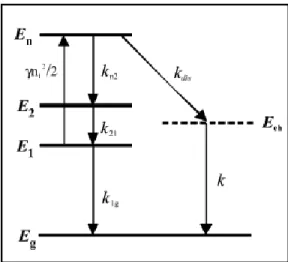
Typically, bundled SWCNTs do not exhibit fluorescence because of the quenching of the excited state due to m-SWCNTs or thermal quenching. Then isolation of s- SWCNTs is necessary to use the photoexcited state of s-SWCNTs. However, even the photoexcitation of isolated s-SWCNTs does not generate a hole (h+) and an electron (e-) because of large binding energy of an exciton (an electron-hole pair). To observe the dissociation of the exciton, Fleming and colleagues used a pulse pumping laser to generate higher exciton state via exciton-exciton annihilations (Figure 1-8).16 An exciton binding energy of 0.41 eV is determined experimentally for a selected nanotube type, the (8,3) tube, from the estimation of the energy difference between an electron- hole continuum and its precursor exciton.
10
Figure 1-8. Schematic description of the electronic structure of the (8,3)tube and the exciton relaxation pathways.
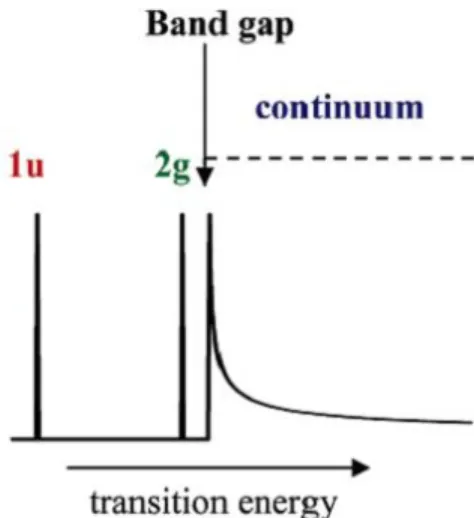
Dukovic and colleagues also determined the exciton binding energies by the use of two-photon excitation spectroscopy.17 Figure 1-9 represents schematic representation of electronic transitions associated with the band gap in semiconducting SWNTs. The states below the band gap are bound excitons. One-photon absorption is allowed for the lowest- lying 1u state, while two-photon absorption is allowed for the 2g state. Absorption of two photons by the 2g and continuum states is followed by emission from the 1u state. Notably, exciton binding energies are large and vary inversely with nanotube diameter. The exciton binding energies were estimated to be 0.42 eV for (8,3)tube and 0.27 eV for (11,7)tube, respectively, which consisted with the determination reported by Fleming.16
11
Figure 1-9. Schematic representation of electronic transitions associated with the band gap in semiconducting SWCNTs.
Wang et. al. also reported the binding energy of exciton, ca. 400 meV for s-SWCNT with 0.8-nanometer diameters, estimated by the two-photon excitation spectroscopy (Figure 1-10).18 The measured fluorescence intensity is shown in a false-color representation as a function of the (two-photon) excitation energy and the (one-photon) fluorescence emission energy. Fluorescence peaks of (7,5), (6,5), (8,3), and (9,1)tubes (aligned with increasing emission energy) can be identified by black circles. The two- photon excitation peaks are shifted substantially above the energy of the corresponding emission feature, as is apparent by comparison with the solid line describing equal excitation and emission energies. The large shift arises from the excitonic nature of SWCNTs optical transitions.
12
Figure 1-10. Contour plot of two-photon excitation spectra of SWCNTs.
Figure 1-11(a) shows a schematic picture of one-photon absorption and emission in carbon nanotubes. E11 indicates the single-particle transition between the lowest sub bands.
Emission occurs from the lowest one-photon active 1u state. Figure 1-11(b) shows two- photon absorption results in the excitation of exciton states. The luminescence of s- SWCNT for excitation below the band gap between 1210 and 1970 nm is shown in Figure 1-11(c). Combining this experiment and theory, Maultzsch and co-workers determined binding energies of 0.3–0.4 eV for nanotubes with diameters between 6.8 and 9.0 Å.19
13
Figure 1-11. (a) Schematic picture of one-photon absorption and emission in carbon nanotubes. (b) Two-photon absorption and emission in carbon nanotubes. (c) Two-photon luminescence spectra of carbon nanotubes.
1.5 s-SWCNTs/C60 Heterojunction for Solar Cells
Recently, construction of heterojunction between s-SWCNT and electron acceptors have been attracted a great attention in order to generate an electron (e-) and a hole (h+) from the exciton in s-SWCNTs. In particular, since C60 can provide an appropriate band offset (~ 130 meV), there is an increasing focus on s-SWCNT/C60 heterojunctio n.
Although Takaguchi and colleagues reported the first example of a water-dispersible
14
SWCNT nanocomposite having an ideal coaxial SWCNT/C60 heterojunction,20 its application for photovoltaic devises was behind in other simple mixture of SWCNTs and C60. Imahori et. al. reported dye-sensitized solar cells by the use of SWCNT/C60 and SWCNT/C70 composites as dye moieties.14,21 Arnold et. al. reported a photovoltaic film device made by deposition of the C60 film on the s-SWCNT film, where the dissociatio n of exciton into h+ and e- at the interface between two films (Figure 1-12).22
Figure 1-12. Exciton dissociation at SWCNT/C60 heterojunction.
2. Fullerodendron
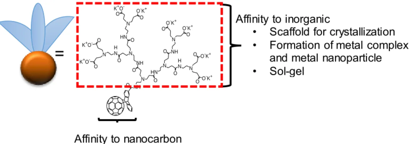
Fullerene-functionalized dendrimers, i.e., fullerodendrimer, are attractive candidates for a variety of interesting features in supramolecular chemistry and materials science.24,25,26 Takaguchi reported the synthesis of water-soluble fullerodendron by a Diels-Alder reaction of C60 with poly(amidoamine) (PAMAM) dendron bearing an anthracene moiety at the focal point.27,28 There are two advantages of the fullerodendron for construction of nanocarbon nanohybrids (Figure 1-13):
15
Figure 1-13. Advantages of fullerodendron for construction of nanocarbon hybrids.
2.1 “C60 moiety can associate with CNTs through π-π interaction.”
Imahori and coworkers reported the formation of SWCNT/C60 and SWCNT/C70 (Figure 1-14a).14,21 A C60 unit of fullerodendron also can associate with SWCNTs. Takaguchi have reported that fullerodendron was very effective at dispersing SWCNTs in water via the formation of supramolecular nanocomposites, although SWCNT/C60 reported by Imahori’s group is not dispersible in any solvents (Figure 1-14b).29
Figure 1-14. a) SWCNTs/C60 composites and b) SWCNTs/fullerodendron.
NH N O
HN NH O
O N
N NH
H N O
O HN
H N
O
O N
N
N
N O
O-K+ O O-K+
OO-K+ O O-K+ O
O-K+ K+O-
O
O K+O-
O K+O-
Affinity to nanocarbon
Affinity to inorganic
• Scaffold for crystallization
• Formation of metal complex and metal nanoparticle
• Sol-gel
=
a) b)
SWCNT C60
fullerodendron
16
2.2 “PAMAM dendron unit of fullerodendron shows the affinity to inorganic materials.”
Three examples of the fabrication of the hybrids consisting of fullerodendron and inorganic materials are described as follows;
(a) Scaffold for the crystallization of inorganic materials in solution system
It is well-known that PAMAM dendrimer is useful for the nucleation site of crystalization.20,30-33 Takaguchi et al. reported the fabrication of C60/CaCO3
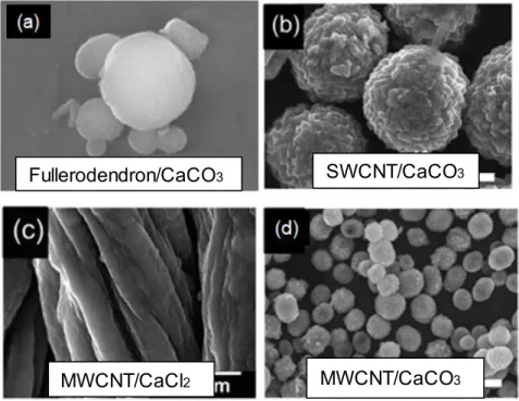
composites,34 and SWCNT/CaCO3 hybrids35 by the use of fullerodendron through the biomimetic crystallization process. Furthermore, MWCNT/CaCO3 and MWCNT/CaCl2 nanohybrids were fabricated by the use of PAMAM dendrimer having a 1,10-bis(decyloxy)decane core.36 The dendritic dispersants act as an effective ‘glue’ between the CNTs and inorganic crystals and enable the facile formation of CNT/inorganic hybrids (Figure 1-15).
17
Figure 1-15. SEM images of nanocarbon/CaCO3 hybrids obtained by the biomime tic crystallization process using dendritic ‘glue’ molecules.
(b) Coordination sites for metal complex and stabilizer of metal nanoparticle
PAMAM dendrimer has many metal-ion-coordination sites, such as tertiary amine groups and CO2–. Therefore, PAMAM dendrimer itself act as ligand of metal ion.37 In addition, subsequent reduction of the complex with NaBH4 affords encapsulated zero- valent metal nanoparticles (Figure 1-16). Takaguchi et. al. reported the direct incorporation of Pt(II) into the shell of SWCNT/fullerodendron supramolec ular nanocomposites (Figure 1-17).38,39
Fullerodendron/CaCO3 SWCNT/CaCO3
MWCNT/CaCl2 MWCNT/CaCO3
18
Figure 1-16. PAMAM dendrimer metal complex and PAMAM dendrimer encapsulated metal nanoparticle.
Figure 1-17. Schematic illustration of SWCNT/fullerodendron/Pt(II) coaxial nano-hybrids.
(c) Catalyst of sol-gel condensation
Takaguchi et. al. reported the SWCNT/fullerodendron/SiO2 coaxial nanohybrid, which was fabricated by sol-gel polycondensation of tetraethoxysilane (TEOS) on the surface of SWCNT/fullerodendron supramolecular nanocomposite (Figure 1-18).40
SWCNT
fullerodendron Pt
19
Figure 1-18. Schematic illustration of SWCNT/fullerodendron/SiO2 coaxial nano-hybrids.
3. Photosensitized Hydrogen Evolution from Water Using SWCNTs/C60 Coaxial Composites
Resent theoretical and experimental studies have indicated that coaxial nanowire structures could potentially improve the carrier collection and overall efficiency relative to bulk semiconductors of the same materials. Takaguchi and coworkers have reported effic ie nt photoinduced electron transfer processes of single-walled carbon nanotube (SWCNT)/anthryl dendron20,40 and SWCNT/fullerodendron20,41 supramolec ular nanocomposites, of which coaxial nanowire structures provide a photofunctional interface between the SWCNT core and the dendron shell. Interestingly, the charge-separated state of SWCNT/fullerodendron is capable of migrating electron to methyl viologen (MV2+) yielding MV•+. Subsequently, the electron pool of MV•+ provides electrons to Pt nanoparticles (PVP- Pt) to generate H2 (Figure 1-19).40
SiO2 SWCNT
fullerodendron
20
Figure 1-19. Energy-level diagram of photocatalytic H2 evolution system using SWCNT/fullerodendron as a photosensitizer.
Takaguchi et. al. reported the introduction of Pt(II) complexes into the shell moieties of the coaxial photosensitizer, SWCNT/fullerodendron, since efficient charge migration and inhibition of the charge recombination might be expected.38 Moreover, direct incorporatio n of Pt(II) co-catalyst into the shell of 6,5-enriched SWCNT/fullerodendron supramolec ular composites.39 Upon chirality-selective photo-excitation using monochromatic light (λ = 680 nm), which is the E22 absorption of (8,3) SWCNTs, we observed the first example for the evolution of H2 (Φ = 0.015) triggered by the photoexcitation of s-SWCNTs. Then we understand that the fullerodendron plays the important role of a n-type semiconducting material of p/n heterojunction, SWCNT/C60 coaxial heterojunction, showing photocatalytic
21
activity to produce H2 from water (Figure 1-20). In order to develop SWCNT/fullerodendro n to a practical photocatalyst, the improvement of the efficiency of the SWCNT-photocatalyst is required.
Figure 1-20. Mechanism of hydrogen evolution using the SWCNT-photocatalyst.
4. Why We Introduce TiOx Layer into the Shell of the SWCNT-photocatalyst
4.1 Transition Metal Oxide (TMO)
As examples of dye-sensitized solar cells or perovskite solar cells, electron extraction layer made of transition metal oxides (TMOs) plays a crucial role for achieving high solar energy conversion efficiency. Meyer et. al. described that TMOs have been used to realize charge-generation junctions for stacked organic light emitting diodes (OLED), sputtering buffer layers for semi-transparent devices, such as organic photovoltaic (OPV) cells.42 Fermi
SWCNT+・/C60−・
BNAH
MV2+
Pt MV+・
SWCNT/C60* hν
BNAH+・ e-
e-
e- e-
SWCNT/C60
2H+ H2
22
level and conduction band level depend on metals, so it is possible to use the most appropriate metals according to the electron transporting materials (Figure 1-21).42
Figure 1-21. CB minimum and VB maximum with respect to the vacuum level (EVL) for MoO3, V2O5 and WO3.
Titanium oxide (TiOx), which is produced by the sol-gel condensation of Ti(OPr)4, is semiconductor materials having a unique set of features which include chemical stability, non-toxicity, low cost, and transparency to visible light. Since TiOx exhibit conduction band levels that match the LUMOs of the C60-derivatives used in OPVs, TiOx is used as a promising prospect for electron-transport material.43,44 There are two important roles of amorphous titanium oxide (TiOx).
4.2 Electron-extraction Layer Attained with a Combination of C60 Layer
Waldauf et. al. demonstrated OPVs containing interfacial TiOx layer between active layer of P3HT:PCBM and ITO exhibit improved fill factors(FF) (Figure 1-22).43
23
Figure 1-22. The normal OPV is based on ITO/PEDOT:PSS/P3HT:PCBM/LiF/Al (left part of figure) and the inverted OPV is based on ITO/TiOx/P3HT:PCBM/PEDOT:PSS/Au (right part of figure).
Kubawara et. al. reported very convenient and useful TiOx thin film, which was fabricated by chemical bath deposition (CBD) method, as the electron extraction- layer of the inverted- type organic solar cell. The ITO/CBD-TiOx/bis-PCBM:P3HT/PEDOT:PSS/Au device shows an improved short-circuit photocurrent (Jsc), open-circuit voltage (Voc), FF, and power- conversion efficiency (η) (Figure 1-23).44
Figure 1-23. Schematic structures of solar cells having CBD-TiOx layer.
24 4.3 Hole Blocking Layer for Organic Solar Cells
Hayakawa et. al. reported the TiOx layer works as an effective barrier to physical damage and chemical degradation, resulting in high durability under aerobic conditions, and also serves as a hole blocking layer, resulting in improved parallel resistance and rectificat io n (Figure 1-24).45
Figure 1-24. a) Series resistance (Rs) and parallel resistance (Rp) of the photovoltaic device with varying thickness of the TiOx layer b) and their rectification ratio.
In summary, titanium oxide (TiOx) can enhance solar cells efficiency because of its unique structure and characteristics. This is mainly related to its high chemical stability, intrinsic transparency to visible light (band gap Eg = 3.2–3.4 eV)46 and to the favorable energy level alignment at the solar cell interfaces, which enables an efficient and selective charge carrier uptake and transport (n-type charge transport as a photoanode and/or as a hole-blocking, electron-extraction layer) from the photoactive material to the front transparent electrode of the solar cell.
a) b)
25 5. Purpose of This Work
As described above, the recent successful realization of SWCNTs-based solar cells and positive effect of TiOx on OPVs containing C60 as a n-type semiconducting material prompt the author to explore the enhancement the photocatalytic activity of SWCNT/fullerodendro n photocatalytic system. A new coaxial photosensitizer with a TiOx shell as an electron- extraction layer covering a SWCNTs/C60 interface was fabricated to investigate the photocatalytic hydrogen evolution from water. Utilization an electron-extracting TiOx shell for photocatalytic hydrogen evolution is of an interest because of its capability of acceleration of the electron transfer under concomitant deceleration of the undesirable back electron- transfer (Figure 1-25).
Figure 1-25. An energy-level diagram of the SWCNT/fullerodendron/TiOx.
Here we describe the fabrication of SWCNT/fullerodendron/TiOx coaxial nano-hybrid s that can be used for the effective photocatalytic evolution of hydrogen (Figure 1-26).
26
Figure 1-26. Hydrogen generation by SWCNT/fullerodednron/TiOx and co-catalyst system using xenon lamp (λ = 450 nm).
hv MV+2 MV.+
PVP-Pt BNAH
H2
H2O C60
SWCNTs
TiOx layer fullerodendron
27 References
1. Ravelli, D.; Dondi, D.; Fagnoni, M.; Albini, A. Chem. Soc. Rev. 2009, 38, 1999.
2. Mao. S. S.; Chen. X. Int. J. Energy Res. 2007, 31, 619.
3. Kisch. H. Adv. Photochem. 2001, 62, 93.
4. Chen. X. B.; Shen. S. H.; Guo. L. J.; Mao. S. S. Chem. Rev. 2010, 110, 6503.
5. (a) Herrmann. J. M. Catalysis Today 1999, 53, 115; (b) Kisch. H. Angew. Chem. Int. Ed.
2013, 52, 812.
6. Takanabe, K.; Kamata, K.; Wang, X.; Antonietti, M.; Kubota, J.; Domen, K. Phys. Chem.
Chem. Phys. 2010, 12, 13020.
7. Teri, W. O.; Jin, L. H.; Charles, M. L. Ann. N.Y. Acad. Sci. 2002, 960, 203.
8. Arnold, M. S.; Green, A. A.; Hulvat, J. F.; Stupp, S. I.; Hersam, M. C. Nat. Nanotechnol.
2006, 1, 60.
9. Charlier, J. C.; Blase, X.; Roche, S. Rev. Mod. Phys. 2007, 79, 677.
10. Hong, S.; Myung, S. Nat. Nanotechnol. 2007, 2, 207.
11. Blackburn, J. ACS Energy Lett. 2017, 2, 1598.
12. Liu, H.; Nishide, D.; Tanaka, T.; Kataura, H. Nature Commun. 2011, 2, 309.
13. Charlier, J. C.; Blase, X.; Roche, S. Rev. Mod. Phys. 2007, 79, 677.
14. Umeyama, T.; Tezuka, N.; Fujita, M.; Hayashi, S.; Kadota, N.; Matano, Y.; Imahori, H.
Chem. Eur. J. 2008, 14, 4875.
15. (a) Ago, H.; Petritsch, K.; Shaffer, M. S. P.; Windle, A. H.; Friend, R. H. Adv. Mater.
1999, 11, 1281; (b) Star, A.; Stoddart, J. F.; Steuerman, D.; Diehl, M.; Boukai, A.; Wong, E. W.; Yang, X.; Chung, S. –W.; Choi, H.; Heath, J. R. Angew. Chem. 2001, 113, 1771.
28
16. Ma, Y.-Z.; Valkunas, L.; Bachilo, S. M.; Fleming, G. R. J. Phys. Chem. B 2005, 109, 15671.
17. Dukovic, G.; Wang, F.; Song, D.; Sfeir, Y. M.; Heinz, F. T.; Brus, L. E. Nano Lett. 2005, 5, 2314.
18. Wang, F.; Dukovic, G.; Brus, L. E.; Heinz, T. F. Science 2005, 308, 838.
19. Maultzsch, J.; Pomraenke, R. S.; Reich, E. C.; Prezzi, D.; Ruini, A.; Molinari, E.; Strano, M. S.; Thomsen, C.; Lienau, C. Phys. Rev. B 2005, 72, 241402.
20. Takaguchi, Y.; Tamura, M.; Sako, Y.; Yanagimoto, Y.; Tsuboi, S.; Uchida, T.;
Shimamura, K.; Kimura, S.; Wakahara, T.; Maeda, Y.; Akasaka T. Chem. Lett. 2005, 34, 1608.
21. Umeyama, T.; Tezuka, N.; Seki, S.; Imahori. H. Adv. Mater. 2010, 22, 1767.
22. Wang, J.; Shea, M. J.; Flach, J. T.; McDonough, T. J.; Way, A. J.; Zanni, M. T.; Arnold, M. S. J. Phys. Chem. C. 2017, (DOI:10.1021/acs.jpcc.7b01005).
23. J. F. Nierengarten, Chem. Eur J. 2000, 6, 3667.
24. Armaroli, N.; Gross, M.; J. F. Nierengarten. Angew. Chem. Int. Ed. 1999, 38, 3730.
25. Thilgen, C.; Diederich. F. Science 1996, 271, 317.
26. Tajima, T.; Ohta, K.; Motoyoshiya, J.; Aoyama, H.; Wakahara, T.; Fujitsuka, M.;
Asakasa, T.; Ito, O.; Takaguchi, Y. Angew. Chem. Int. Ed. 2002, 41, 817.
27. Takaguchi, Y.; Sako, Y.; Yanagimoto, Y.; Tsuboi, S.; Motoyoshiya, J.; Aoyama, H.;
Wakahara, T.; Akasaka, T. Tetrahedron Lett. 2003, 44, 5777.
28. Takaguchi, Y.; Yanagimoto, Y.; Tajima, T.; Ohta, K.; Motoyoshiya, J.; Aoyama, H.
Chem. Lett. 2002, 1102.
29. Naka, K.; Tanaka, Y.; Chujo, Y. Chem. Commun. 1999, 1931.
29
30. Naka, K.; Tanaka, Y.; Chujo, Y. Langmuir 2002, 18, 3655.
31. Naka, K.; Tanaka, Y.; Chujo, Y. Bull. Chem. Soc. Jpn. 2002, 75, 2541.
32. Naka, K. Top. Curr. Chem. 2003, 228,141.
33. Talukdar, B.; Yanagimoto, Y.; Tsuboi, S.; Ichihara, M.; Ohta, K.; Takaguchi, Y. Bull.
Chem. Soc. Jpn. 2006, 79, 1983.
34. Tajima, T.; Tsusi, A.; Fujii, T.; Takada, J.; Takaguchi, Y. Polymer J. 2012, 44. 620.
35. Nishimura, S.; Tajima, T.; Hasegawa, T.; Tanaka, T.; Takaguchi, Y.; Oaki, Y.; Imai, H.;
Can. J. Chem. 2017. Inpress (doi.org/10.1139/cjc-2017-0022).
36. Crooks, R. M.; Zhao, M.; Sun, L.; Chechik, V.; Yeung, L. K. Acc. Chem. Res. 2001, 34, 3.
37. Sasada, Y.; Tajima, T.; Wada, T.; Uchida, T.; Nishi, M.; Ohkubo, T.; Takaguchi, Y. New J. Chem. 2013, 37. 4214.
38. Murakami, N.; Tango, Y.; Miyake, H.; Tajima, T.; Nishina, Y.; Kurashige, W.; Neghisi, Y.; Takaguchi, Y. Sci. Rep. 2017, 7, 43445.
39. Tajima, T.; Sakata, W.; Wada, T.; Tsusui, A.; Nishimoto, S.; Miyake, M.; Takaguchi, Y.
Adv. Mater. 2011, 23, 5750.
40. Sandanayaka, A. S. D.; Takaguchi, Y.; Uchida, T.; Sako, Y.; Morimoto, Y.; Araki Y.;
Ito, O. Chem. Lett. 2006, 1188.
41. Sandanayaka, A. S. D.; Takaguchi, Y.; Sako, Y.; Tamura M.; Ito, O. Adv. Sci. Lett. 2010, 3, 353.
42. Meyer, J.; Hamwi, S.; Kröger, M.; Owalsky, W.; Riedl, T.; Kahn, A. Adv. Mater. 2012, 24, 5408.
30
43. Waldauf, C. M.; Morana, P.; Denk, P.; Schilinsky, K. C.; Choulis, S. A.; Brabec, C. J.
Appl. Phys. Lett. 2006, 89, 233517.
44. Kuwabara, T.; Nakayama, T.; Uozumi, K.; Yamaguchi, T.; Takahashi, K. Sol. Energy Mater. Sol. Cells. 2008, 92, 1476.
45. Hayakawa, A.; Yoshikawa, O.; Fujieda, T.; Uehara, K.; Yoshikawa, S. App. Phys. Lett.
2007, 90, 163517.
46. (a) Partridge, K. S.; Smith, D. K.; Dykes, G. M.; McGrail, P. T. Chem. Commun. 2001, 27, 319; (b) Hirst, A. R.; Smith, D. K. Org. Biomol. Chem. 2004, 2, 2965.
31
Chapter 2
Effect of TiO
xShell on Photocatalytic Activity of the SWCNT-
Photocatalyst
32 2.1 Introduction
The interfaces between metal oxides and organic compounds play an important role in the field of organic electronics, which include organic light-emitting devices (OLEDs),1,2 organic photovoltaic cells (OPVs),1,3 dye-sensitized solar cells (DSSCs),1c and transistors.4 To improve the device performance, these interfaces can often be modified by insertion of a functional interfacial layer. For example, transparent titanium oxide (TiOx) exhibit electronic levels that match the LUMOs of the C60-derivatives used in OPVs well, which renders TiOx
a promising prospect for electron-transport materials.5,6 Waldauf and co-workers have prepared OPVs with an ITO/TiOx/RR-P3HT:PCBM/PEDOT:PSS/Au structure using coating techniques, and demonstrated that these OPVs exhibit improved fill factors (FF).5 Kuwabata et al. have reported efficient inverted BHJ solar cells that contain TiOx as the electron- extraction layer,6 which resulted in an improved short-circuit photocurrent (Jsc), open-circuit voltage (Voc), FF, and power-conversion efficiency (η).
Meanwhile, coaxial nanowires with a donor-acceptor heterojunction have shown great potential for applications in innovative photofunctional materials. A SWCNTs heterojunctio n can be constructed from two segments of SWCNTs through topological defects,7 such as a pentagon-heptagon (5–7) pair defect,8 which could influence the optical, electronic, and mechanical properties of the constituent SWCNTs. Such a heterojunction provides not only an efficient way to design circuits with different electrical properties but also the potential to serve as a functional component in nanodevices,9 rectifying diodes,10 and switches.
33
SWCNTs are considered ideal supports for photocatalysts because SWCNTs have a large electron storage capability of one electron per 32 carbon atoms that reduces electron–ho le recombination have a high specific surface area (SSA) of 1315 m2 g-1 for photocatalyst loading can act as a photosensitizer that enlarges titanium oxide (TiOx) absorption bandwidth and are transparent layer and highly electrically conducting for efficient electron transport.11-
14 From this viewpoint the author exploring a new coaxial photosensitizer with a TiOx shell as an electron-extraction layer that covers a photo-functional SWCNTs/C60 interface. Here the author describe the fabrication of SWCNT/fullerodendron/TiOx coaxial nano-hybrids that can be used for the effective photocatalytical evolution of hydrogen (Figure 2-1).
Figure 2-1. Fabrication of SWCNT/fullerodendron/TiOx.
34 2.2 Experimental Section
2.2.1 General
TEM measurements for the composites were conducted using a Hitachi S-5200. The specimens for the measurements were prepared by applying a few drops of the sample solution onto a holey carbon-coated copper grid (Ouken-Shoji 200-Abmesh), and then evaporating the solvent. The absorption data were recorded on a Shimadzu UV-3150 spectrophotometer using a standard cell with a path length of 10 mm. Atomic force microscopy (AFM) observation was carried out using a Seiko SPA 400-DFM and the samples for the observations were prepared by placing a drop of SWCNT/fullerodendron/TiOx
coaxial nanohybrids aqueous solution on freshly cleaved mica, then allowing them to dry with a dryer FT-IR spectra were recorded using Shimadzu IR Affinity-1. Three-dimensio na l fluorescence spectra data were obtained using a spectrofluorometer (Shimadzu, NIR-PL system). SWCNTs (HiPco) were purchased from Unidym Co. Fullerodendron and SWCNT/fullerodendron supramolecular nanocomposites were prepared according to the reported procedure.15 All other reagents were purchased from Kanto Kagaku Co., Ltd, Aldrich Chemical Co., and Tokyo Kasei Co., Ltd., and were used as received.
35
2.2.2 Preparation of SWCNT/fullerodendron supramolecular nanocomposites
SWCNTs (HiPco: 1.0 mg) were placed in a water solution (10 mL) of the fullerodend ro n (25.5 mg, 0.01 mmol) and then sonicated with a bath type ultrasonifier (ULTRASONIC CLEANER vs-D100, 110 W, 24 kHz) at 17–25 ˚C for 4 h. After the suspension was centrifuged at 3000 g for 30 min, a black-colored supernatant dispersion, which included SWCNT/fullerodendron supramolecular nanocomposites and superfluous fullerodendro n, was collected. The SWCNT/fullerodendron nanocomposites were purified by dialysis for 3 days using dialysis tubing (SPECTRUM RC MEMBRANES Pro 4) to remove superfluo us fullerodendron. The dialysis process was continued until the dialysate showed no absorption change at 258 nm in UV-vis spectra. This dialysate solution was used for further experime nt as a stock solution of SWCNT/fullerodendron supramolecular nanocomposites.15
2.2.3 Fabrication of SWCNT/fullerodendron/TiOx coaxial nanohybrids
An aqueous solution of SWCNT/fullerodendron nanocomposites (1 mL, 0.1 mg SWCNTs) was added by HCl (1.0 N, 2.8 µL) adjust pH 3 then strring for 15 min to homogeneous solution. Titanium tetra isopropoxide (TTIP) (5 mg, 1.8 × 10⁻² mmol) was dissolved with ethanol (4 mL) then, centrifugation at 4000 rpm for 10 minutes. The supernatant was added to the SWCNT/fullerodendron composite at 0 ºC and gently stirred for 24, 48 and 72 h.
36 2.2.4 Synthesis of Colloidal PVP-Pt
An aqueous solution (10 mL) of H2PtCl6·6H2O (0.034 g, 66 µmol) was dropped into poly(vinylpyrrolidone) (PVP, 0.320 g, Mw = 40.000 g/mol) in H2O (20 mL) at room temperature. After diluting with H2O (20 mL) and ethanol (50 mL), the solution was stirred under reflux conditions for 2 h. After the removal of solvents, the resulting precipitate was dissolved in H2O (15 mL). After centrifugation at 15000 ppm for 13 h, a clear phase was collected to obtain a colloidal PVP-Pt.
2.2.5 Hydrogen evolution
Typically, 150 mL of an aqueous solution consisting of SWCNT/fullerodendron/TiOx (1 mL), Tris-HCl buffer (3.5 mL in H2O, pH 7.5, 5 mM), methyl viologen dichloride (92.4 mg, 359 mol), 1-benzyl-1,4-dihydronicotinamide (BNAH) (38.6 mg, 180 mol), and a colloida l PVP-Pt (15 mL in H2O, of which Pt atom content was 512 µmol) in a Pyrex reactor was degassed for five cycles and purged with Ar. Upon vigorous stirring at 25 ºC, that solution was irradiated with a 300 W Xenon arc light (Ushio model UXL 500 W) through the band- pass filter (450 ± 5 nm: ASAHI SPECTRACO, M. C. 450/10 nm 50 × 50). After a designated period of time, the cell containing the reaction mixture was connected to a gas chromatograph (Shimadzu, TCD, molecular sieve 5A: 2.0 m × 3.0 mm, Argon carrier gas) to measure the amount of H2 above the solution. The apparent quantum yield (AQY) is defined as follows.
AQY = (number of H2 generated × 2)/(number of photons absorbed), which was evaluated
37
from a change in power of the transmitted light, measured using a power meter (Photo-Radio meter Model HD 2302.0 coupled with the irradiance measurement probe LP 471 RAD having an exposure window diameter of 1.6 cm) placed behind the cell parallel to the irradiation cell face.16
2.3 Preparation SWCNTs Solution for Spray Coating
SWCNTs (1.0 mg) were mixed 1 wt% sodium dodecyl sulfate (SDS) to make SDS dispersion with a concentration of 1 mg/mL. Such suspension was ultrasonically agitated using a probe sonicator with an output sonication power of 2 W for 4 h followed by centrifugation at 3000 G for 30 min in order to separate out the undissolved SWCNTs bundles and catalyst impurities.
2.3.1 Preparation Thin Film SWCNTs
FTO substrates were cleaned with ethanol:acetone (90 : 10) by sonication process for 30 min, then immersed in the hot ethanol for 10 min, drying FTO substrate with Nitrogen gasses.
The FTO substrate was heated in air at 110 °C for 1 h to promote SWCNT/SDS solution were directly spray-coated onto the FTO substrates by using an airbrush pistol. During the spraying process, the FTO substrates were maintained at 110 oC in order to prevent the formation of fine droplets on the surface of the FTO substrates. When the spray process terminated, the films was immersed into deionized water for 24 h to remove the superfluous
38
SDS surfactant and then dried at 90 °C for 1-2 h. Special care for the choice of the (6,5)- enriched SWCNTs concentration, the nozzle size of the pistol, and the distance from the pistol nozzle to the FTO substrates should be simultaneously done in order to obtain unifor m ultrathin SWCNTs films with a high quality.17
2.3.2 Decoration Thin Film SWCNT with Fullrodendron
An aqueous solution of the fullerodendron (10 mL, 40 μM) was added by 3 L HCl (1N) to adjust pH 3 then thin film FTO/SWCNT was immersed for 24 h in the fullerodendro n acidic solution for decorated surface of thin film FTO/SWCNTs. Therefore rinsed thin film FTO/SWCNT/fullerodendron in the water surface for 3 time to removal from superfluous of fullerodendron on the surface.
2.3.3 Decoration TiOx on the Surface of Thin Film SWCNT/fullerodendron
Titanium tetra isopropoxide (TTIP) (5 mg, 1.8 × 10⁻² mmol) was dissolved with ethanol (4 mL) then, centrifugation at 4000 rpm for 10 minutes. Then pipette supernatant 20 L and was dropped into spin-coated on the substrate in air at 1000 rpm for 60 s and kept in the ambient at room temperature for 1 h. A thermal treatment at 85 °C for 10 min was observed to be beneficial for the device performance.
39 2.4 Results and discussion
2.4.1 Fabrication of SWCNT/fullerode ndron/TiOx
SWCNT/fullerodendron/TiOx nano-hybrids were fabricated by polycondensation reaction of titanium tetra isopropoxide (TTIP)18 using SWCNT/fullerodendron supramolecular nano- composites as catalytic scaffolds according to previous reports on SWCNT/fullerodendron/SiO2 nano-hybrids.19 In a typical run, HCl (1.0 N, 2.8 µL) was added to an aqueous solution of SWCNT/fullerodendron nano-composites (1 mL).
Subsequently, TTIP (20 µL, 0.17 mM) in ethanol was added to the solution at 0 ˚C. After gentle stirring for 24, 48, and 72 h, a dispersion of SWCNT/fullerodendron/TiOx was obtained.
2.4.2 Characterization of SWCNT/fullerodendron/TiOx
a) Scanning Electron Microscopy (SEM)
The morphology of the SWCNT/fullerodendron/TiOx nano hybrids was examined by scanning electron microscopy (SEM). Here we shown SEM images SWCNT/fullerodendron/TiOx after sol-gel reaction for 24, 48 and 72 h. The tiny fibers with 1–3 m length and 60–120 nm diameters were observed after sol-gel reaction for 48 h.
Thickness of the very thin nanofiber shown in the white rectangle in Figure 2-2 is ca. 50 nm.
40
Figure 2-2. The shell thickness affecting the photoactivity.
b)
Transmission Electron Microscopy (TEM)The TEM images prepared in the water solution containing SWCNT/fullerodendron/TiOx
coaxial nano-hybrids. In addition to a clear coaxial nanowires structure of SWCNT/fullerodendron/TiOx that a uniformly thick shell composed of nano-sized TiOx
covered the SWCNT/fullerodendron nano-wire with 50 nm wide (Figure 2-3).
Figure 2-3. TEM image of SWCNT/fullerodendron/TiOx supramolecular nanohybrids.
41
c)
Atomic Force Microscopy (AFM)Atomic force microscopy (AFM) is a classic technique for characterising SWCNTs and provides vital information on their diameter, length and degree of individualisation. When studying the dispersion quality using AFM, attention usually focuses only on the linear features associated with the SWCNTs. Other non-SWCNTs species are often simply assigned as impurities, such as amorphous carbon or catalyst particles inherited from SWCNTs synthesis.20
In addition the height profiles in the AFM analysis revealed that the thickness of SWCNT/fullerodendron/TiOx coaxial nano-hybrids (~15 nm) is higher than that of the SWCNT/fullerodendron supramolecular nano-composite (2-3 nm) (Figure 2-4). Based on these results, the thickness of the TiOx layer was estimated to be 6-7 nm. These observations are consistent with the SWCNT/fullerodendron/TiOx coaxial nano-hybrid structure, the SWCNT-core surrounded by the fullerodendrons, coated by the outer TiOx shell (Figure 2- 5).
Figure 2-4. AFM image of SWCNT/fullerodendron/TiOx supramolecular nanohybrids.
42
Figure 2-5. Confirmation thickness of each layer in the SWCNT/fullerodendron/TiOx.
d) Photoluminescence Mapping of SWCNT/Fullerodendron/TiOx
The photoluminescence of SWCNTs is consistent with isolated SWCNTs and therefore characterization of isolated SWNTs is possible. Individual SWCNTs dissolved in a surfactant solution exhibit photoluminescence in the near-IR region.21 The coaxial nanowire structure with isolated SWCNTs was confirmed by three-dimensional photoluminescence (PL) intensity mapping in D2O, allowed assigning four intense peaks with reasonable certainty to the (9,4), (8,6), (7,6), and (8,4) SWCNTs.22 It should be noted that the coaxial structure is maintained, i.e., the formation of bundles and/or aggregation of the SWCNTs after the formation of the SWCNT/fullerodendron/TiOx coaxial nano-hybrids was not observed (Figure 2-6).
43
Figure 2-6. Three-dimensional fluorescence spectra of SWCNT/fullerodendron/TiOx coaxial nano hybrids.
e) Spectroscopy Visible-Near Infrared (NIR)
Confirmation layer the TiOx layer of the SWCNT/fullerodendron/TiOx nano hybrid shows high optical transparency in the visible and near infrared (NIR) region. (Figure 2-7) shows the Vis-NIR absorption spectra of the SWCNT/fullerodendron supramolec ular nanocomposites and the SWCNT/fullerodendron/TiOx coaxial nanohybrids. The absorption of the SWCNT/ fullerodendron/TiOx coaxial nano-hybrids is smaller than that of the SWCNT/fullerodendron composites, as the concentration of the SWCNT/fullerodendron/TiOx coaxial nano-hybrids was lowered during the sol–gel condensation process. However, the absorption and/or scattering due to the TiOx layer on the shell should be negligible on account of the nano-sized thickness of the TiOx layer. From the
44
comparison of absorption bands (500-1350 nm) before and after the sol-gel condensation, we can be found four kinds of type SWCNTs such as (9,4), (8,6), (7,6), and (8,4) that allowed assigned in the photoluminescence (PL) mapping spectra.22
Figure 2-7. Vis-NIR spectra of SWCNT/fullerodendron supramolecular nanocomposites and SWCNT/ fullerodendron/TiOx coaxial nanohybrids.
f) Infrared Spectra of SWCNT/fullerodendron/TiOx
To obtain a better understanding of the fullerodendron/TiOx junction, FTIR spectroscopic measurements of the SWCNT/fullerodendron/TiOx nano-hybrid were conducted (Figure 2- 8). The IR spectra of the SWCNT/fullerodendron/TiOx nanohybrids exhibit the C=O stretching modes at 1725 cm-1, which is shifted toward higher frequencies than those of the SWCNT/fullerodendron supramolecular nano-composites (1680 cm-1). This result indicates the formation of Ti–OCOR bonds at the termini of the fullerodendrons.23 The sharp absorption band observed at 635 cm-1 was ascribed to the Ti-O-Ti moieties, while the strong
45
absorption band at 1055 cm-1 was attributed to the Ti-O-C stretching mode. Based on these observations, we concluded that the TiOx layer is attached onto the surface the SWCNT/fullerodendron supramolecular nano-composites without significant damage to the
Figure 2-8. IR spectra of (i) SWCNT/fullerodendron, (ii) SWCNT/fullerodendron/TiOx and (iii) TiOx.
g) Raman Spectra of SWCNT/fullerodendron/TiOx
Raman scattering is well known as an important technique to characterize the different form of carbon material. Recently, the resonance Raman scattering (RRS) technique has been shown to provide a powerful tool for studying and characterizing single-walled carbon nanotubes (SWCNTs), first for bundles and recently for isolated SWCNTs.24 In addition to clear a Raman spectrum of the SWCNT/fullerodendron/TiOx coaxial nano-hybrids showed
46
typical scattering of the disorder induced mode (D) and the tangential displacement mode (TDM; also called the G band), which were observed at 1339 and 1610 cm–1, respectively (Figure 2-9).25,26 The very small intensity of the D-band indicates that the SWCNTs within the composites did not sustain any substantial damage. Broad peaks at 610 and 425 cm-1 were ascribed to TiOx.27
Figure 2-9. Raman spectra for SWCNT/fullerodendron (Gray line) and SWCNT/
fullerodendron/TiOx (black line).
2.4.3 Application of SWCNT/fullerodendron/TiOx Coaxial Nano-hybrids 2.4.3.1 Hydrogen Evolution from SWCNT/fullerodendron/TiOx
To probe the beneficial aspects of theincorporation of the transparent electron-extract io n layer into an SWCNT/fullerodendron coaxial photosensitizer, we explored the photocatalyt ic
47
evolution of hydrogen from water using a system based on the SWCNT/fullerodendron/TiOx
supramolecular nano-composites coupled with colloidal poly(vinylpyrrolidone)-plat inum (PVP-Pt). The plots of the total amount (4.0 mol/h) proceeded steadily and an inductio n period or decreasing activity was not observed during 6 h of irradiation. Although the SWCNT/fullerodendron supramolecular nanocomposites also worked as a photosensit izer for the evolution of hydrogen, the reaction rate of the hydrogen generation (1.9 mol/h) is lower than that of SWCNT/fullerodendron/TiOx nano hybrids (4.0 mol/h). Given that the absorbance of the SWCNT/fullerodendron/TiOx nano-hybrids is lower than that of the SWCNT/fullerodendron supramolecular nano-composites, the photocatalytic activity of the SWCNT/fullerodendron/TiOx nano-hybrids must be higher than that of the SWCNT/fullerodendron supramolecular nano-composites. In order to compare the efficie nc y of the photocatalytic evolution of hydrogen between the SWCNT/ fullerodendro n supramolecular nano composite and the SWCNT/fullerodendron/TiOx nano-hybrids photocatalysts, we evaluated their quantum yields by using monochromic light (λ = 450 ±5 nm), which revealed apparent quantum yields (AQYs) for the evolution of hydrogen (2 × number of molecules of hydrogen generated/number of photons absorbed) of 0.47 (SWCNT/fullerodendron/TiOx) and 0.12 (SWCNT/fullerodendron) (Figure 2-10).
48
Figure 2-10. Time dependence of the evolution of hydrogen from water using SWCNT/fullerodendron (▲) or SWCNT/fullerodendron/TiOx (♦).
2.5 Energy-level diagram of the SWCNT/fullerodendron/TiOx
An energy-level diagram of the conduction (C1 and C2) and valence bands (V1 and V2) of (7,6) SWCNT,28 which is one of the most commonly encountered types of CNTs in HiPco, together with the LUMO levels of C60,29 MV2+,30 BNAH,31 and the energy level of Pt and TiOx is shown in (Figure 2-11). A distinctive advantage of the coaxial architecture is that the carrier separation occurs in the shorter radial direction as opposed to the longer axial direction.
Moreover, the energy-level diagram indicates that the electron-extraction layer of TiOx not only decelerates the electron back-transfer, but also accelerates the electron forward-transfer from the conduction band of TiOx to the LUMO of MV2+, thus leading to an effic ie nt electron-transfer pathway.
49
Figure 2-11. Energy-level diagram of the SWCNT/fullerodendron/TiOx coaxial photocatalyst system.
2.6 Fabrication Thin Film FTO/SWCNT/fullerodendron/TiOx
Thin film FTO/SWCNT/fullerodendron/TiOx was fabricated by spray coating dispersatio n of SWCNT (1.0 mg) in the SDS solution (1 wt%). During the spray coating process, the FTO substrates were maintained at 110 oC in order to prevent the formation of fine droplets on the surface of the FTO substrates. When the spray process terminated, the films was immersed into deionized water for 24 h to remove the superfluous SDS surfactant and then dried at 90 °C for 1-2 h. The obtained films were immersed in an aqueous solution of fullerodendro n to decorate the surface of the film photocathode with fullerodendron. The photocathode was decorated with TiOx by the polycondensation reaction of titanium tetra isopropoxide (TTIP).
50
2.6.1 Hydrogen Evolution from Thin Film SWCNT/fullerodendron/TiOx
A steady generation of H2 generation from recycles used of the thin film FTO/SWCNT/fullerodendron/TiOx first used (1.82 mol/h) and second used (1.48 mol/h) was observed upon exposure to a light of wavelength 422 ± 5 nm nm with a 300 W Xenon arc lamp (Figure 2-12). It is notable that 81% of H2-evolving activity was remained for the second use of a spray-coated film of SWCNT/fullerodendron/TiOx on a FTO plate coupled with colloidal poly(vinylpyrrolidone)platinum (PVP-Pt) after the 6 hour H2 evolutio n reaction.
Figure 2-12. Time dependencies of the H2 production from water in the systems of recycle use of the thin film FTO/SWCNT/fullerodendron/TiOx catalyzed by a colloidal PVP-Pt. Thin film FTO/SWCNT/fullerodendron/TiOx first used (■) and second used (♦).
51 2.6.2 Photoelectrode Hydrogen Evolution
The photoelectrochemical measurements were carried out in a typical three-electrode electrochemical cell under Xenon lamp (λ > 422 nm). The as-prepared photoelectrode thin film FTO/SWCNT/fullerodendron/TiOx act as working electrode, Ag/AgCl as reference electrode, and Pt wire were used as the counter electrode, respectively. The photoelectrode measurements were conducted in 0.1 M Na2SO4/NaOH solution (pH = 7). The result show that enhancement of the photoelectrode thin film FTO/SWCNT/fullerodendron/TiOx can be evaluated hydrogen at wavelength 550 nm (green light) and also at 650 nm (red light) using bias potential 0.3 V (Vs Ag/AgCl).
2.7 Summary
A bespoke SWCNTs photocatalyst with an electron-extracting TiOx shell was fabricated.
On account of the presence of the TiOx shell, the SWCNT/fullerodendron/TiOx coaxial nanowire exhibits a high activity in the catalytic evolution of H2 from water under irradiatio n with visible light, because the electron-extracting TiOx layer accelerates the electron forward - transfer under concomitant deceleration of the undesirable back electron-transfer (Figure 2- 13). Incorporations of the TiOx electron-extraction layer to the p-n heterojunction consisting of s-SWCNT (p-type) and C60 (n-type) is very useful and efficient to provide anionic lateral surface to improve efficiency photocatalytic H2 evolution from water, make robustness thin film based on SWCNT/C60, fullerodendron and TiOx.
52
Figure 2-13. Efficiency TiOx shell to enhance photocatalytic hydrogen evolution from water under visible light.
53 References
1. For reviews, see: (a) Meyer, J.; Hamwi, S.; Kröger, M.; Kowalsky, W.; Riedl, T.; Kahn, A. Adv. Mater. 2012, 24, 5408; (b) Zilberberg, K.; Meyer, J.; Riedl, T. J. Mater. Chem.
C. 2013, 1, 4796; (c) Ratcliff, E. L.; Zacher, B.; Armsrong, N. R. J. Phys, Chem. Lett.
2011, 2, 1337.
2. (a) Tokito, S.; Noda, K.; Taga, Y. J. Phys. D: Appl. Phys. 1996, 29, 2750; (b) Kanno, H.; Holmes, R. J.; Sun, Y.; Kena-Cohen, S.; Forrest, S. R. Adv. Mater. 2006, 18, 339;
(c) Reynold, K. J.; Barker, J. A.; Greenham, N. C.; Friend, R. H.; Frey, G. L. J. Appl.
Phys. 2002, 92, 7556; (d) Chu, C.-W.; Chen, C.-W.; Li, S.-H.; Wu, E. H. –E.; Yang, Y.
Appl. Phys. Lett. 2005, 86, 253503; (e) You, H.; Dai, Y.; Zhang Z.; Ma, D. J. Appl. Phys.
2007, 101, 026105; (f) Meyer, J.; Hamwi, S.; Kröger, M.; Kowalsky, W.; Riedl, T.; Kahn, A. Adv. Mater. 2012, 24, 5408; (g) Bolink, H. J.; Coronado, E.; Repetto, D.; Sessolo, M.; Barea, E. M.; Bisquert, J.; Garcia-Belmonte, G.; Prochazka, J.; Kavan, L. Adv. Funct.
Mater. 2008, 18, 145.
3. For reviews, see: (a) Wang, F.; Tan, Z.; Li, Y. Energy Environ. Sci. 2015, 8, 1059; (b) Chen, S.; Manders, J. R.; Tsang, S.-W.; So, F. J. Mater. Chem. 2012, 22, 24202.
4. Cho, S.; Seo, J. H.; Lee, K.; Heeger, A. J. Adv. Funct. Mater. 2009, 19, 1459.
5. Waldauf, C.; Morana, M.; Denk, P.; Schilinsky, P.; Coakley, K.; Choulis, S. A.; Brabec, C. J. Appl. Phys. Lett. 2006, 89, 233517.
6. Kuwabara, T.; Nakayama, T.; Uozumi, K.; Yamaguchi, T.; Takahashi, K. Sol. Energy Mater. Sol. Cells, 2008, 92, 1476.
7. Wu, G.; Li, B. Phys. Rev. B 2007, 76, 085424.
8. Ebbesen, T. W.; Takaada, T. Carbon 1995, 33, 973.
54
9. Bandaru, P. R.; Daraio, C.; Jin, S.; Rao, A. M. Nature Mater. 2005, 4, 663.
10. Yao, Z.; Postma, H. W. C.; Balents, L.; Dekker, C. Nature 1999, 402, 273.
11. Kongkanan, A.; Kamat, P. V. ACS Nano 2007, 1, 13.
12. Martel, R.; Schmidt, T.; Shea, H. R.; Hertel, T.; Avouris, P. Appl.Phys.Lett. 1998, 73, 2447.
13. Peigney, A.; Laurent, C.; Flahaut. E.; Bacsa, R. R.;Rousset, A. Carbon 2001, 39, 507.
14. Woan, K.; Pyrgiotakis, G.; Sigmund, W. Adv.Mater. 2009, 21, 2233.
15. Takaguchi, Y.; Tamura, M.; Sako, Y.; Yanagimoto, Y.; Tsuboi, S.; Uchida, T.;
Shimamura, K.; Kimura, S.; Wakahara, T.; Maeda, Y.; Akasaka T. Chem. Lett. 2005, 34, 1608.
16. Sasada, Y.; Tajima, T.; Wada, T.; Uchida, T.; Nishi, M.; Ohkubo, T.; Takaguchi, Y. New J. Chem. 2013, 37. 4214.
17. Liu, Q.; Fujigaya, T.; Cheng, H. M.; Nakashima, N. J. Am. Chem. Soc. 2010, 132, 16581.
18. Pasquarelli, R. M.; Ginley, D. S.; O'Hayre, R. Chem. Soc. Rev. 2011, 40, 5406.
19. Tajima, T.; Sakata, W.; Wada, T.; Tsusui, A.; Nishimoto, S.; Miyake, M.; Takaguchi, Y.
Adv. Mater. 2011, 23, 5750.
20. Yau, H. C.; Bayazit, M. K.; Steinkea, J. H. G.; Shaffer, M. S. P. Chem. Commun. 2015, 51, 16621.
21. a) O’Connell, M. J.; Bachilo, S. M.; Huffman, C. B.; Moore, V. C.; Strano, M. S.; Haroz, E. H.; Rialon, K. L.; Boul, P. J.; Noon, W. H.; Kittrell, C.; Ma, J.; Hauge, R. H.; Weisman, R. B.; Smalley, R. E. Science 2002, 297, 593; b) Bachilo, S. M.; Strano, M. S.; Kittrell, C.; Hauge, R. H.; Smalley, R. E.; Weisman, R. B. Science 2002, 298, 2361.
22. Liu, H.; Nishide, D.; Tanaka, T.; Kataura, H. Nature Commun. 2011, 2, 309.
55
23. Perrin, F. X.; Nguyen, V.; Vernet, J. L. J. Sol-Gel Sci. Technol. 2003, 28, 205.
24. Jario. A.; Filho, A. G. S.; Dresselhaus, M. S.; Dresselhaus, G.; Swan, A. K.; Unlu, M.
S.; Goldberg, B. B.; Pimenta, M. A.; Hafner, J. A.; Lieber, J. M.; Sito, R. Mat. Res. Soc.
Symp. Proc. 2002, 706.
25. Jeníkováa, M.; Zakuťanskáb, K.; Kováča, J.; Girmanb, V.; Kopčanskýa, P.;
Tomašovičová, N. Acta Phys. Polonica A. 2016, (DOI: 10.12693/APhysPolA.131.952).
26.
Dresselhaus, M. S.; Dresselhaus, G.; Saito, R.; Jorio, A. Phys. Rep. 2005, 47, 409.27. Wen, Z.; Ci, S.; Mao, S.; Cui, S.; Lu, G.; Yu, K.; Luo, S.; He, Z.; Chen, J. J. Power Sources 2013, 234, 100.
28. Tanaka, Y.; Hirana, Y.; Niidome, Y.; Kato, K.; Saito, S.; Nakashima, N. Angew. Chem.
Int. Ed. 2009, 48, 7655.
29. Takaguchi, Y.; Sako, Y.; Yanagimoto, Y.; Tsuboi, S.; Motoyoshiya, J.; Aoyama, H.;
Wakahara, T.; Akasaka, T. Tetrahedron Lett. 2003, 44, 5777.
30. Ito, M.; Kuwana, T. Electroanal. Chem. 1971, 32,415.
31. Zhu, X. Q.; Zhang, M. T.; Yu, A.; Wang, C. H.; Cheng, J. P. J. Am. Chem. Soc. 2008, 130, 2501.
56