鳥取大学研究成果リポジトリ
Tottori University research result repository
タイトル
Title
Thousand-atom ab initio calculations of excited statesat organic/organic interfaces: toward first-principles investigations of charge photogeneration著者
Auther(s)
Fujita, Takatoshi; Alam, Md. Khorshed; Hoshi, Takeo掲載誌・巻号・ページ
Citation
Physical Chemistry Chemical Physics , 20 (41) : 26443- 26452刊行日
Issue Date
2018-11-07資源タイプ
Resource Type
学術雑誌論文 / Journal Article版区分
Resource Version
著者版 / Author権利
Rights
© Royal Society of Chemistry 2018DOI
10.1039/C8CP05574BThousand-Atom Ab Initio Calculations of Excited States at
Organic
/Organic Interfaces: Toward First-Principles Investigations of
Charge Photogeneration
Takatoshi Fujita
Institute for Molecular Science, Okazaki, Aichi 444-0865, Japan∗
Md. Khorshed Alam
Department of Physics, University of Barisal, Barisal-8200, Bangladesh
Takeo Hoshi
Department of Applied Mathmatics and Physics, Tottori University, Tottori 680-8550, Japan
Abstract
Predicting electronically excited states across electron-donor/electron acceptor interfaces is essential for understanding charge photogeneration process in organic solar cells. However, organic solar cells are large and disordered systems, and their excited states cannot be easily accessed by conventional quantum chem-istry approaches. Moreover, a large number of excited states must be obtained to fully understand the charge separation mechanism. Recently, we have developed the novel fragment-based excited state method which can efficiently calculate a large number of states in molecular aggregates. In this article, we demonstrate the large-scale excited-state calculations by investigating interfacial charge transfer (ICT) states across the electron-donor/electron acceptor interfaces. As the model systems, we considered the face-on and edge-on configurations of pentacene/C60bilayer heterojunction structures. Those model structures contain
approx-imately 1.8×10⁵ atoms, and their local interface regions containing 2,000 atoms were treated quantum
mechanically, embedded in the electrostatic potentials from remaining parts. Therefore, the charge delo-calization effect, structural disorder, and the resulting heterogeneous electrostatic and polarizable environ-ments were taken into account in the excited-state calculations. The computed energies of the low-lying ICT states are in reasonable agreement with experimental estimates. By comparing the edge-on and face-on configurations of the pentacene/C60interfaces, we discuss the influence of interfacial morphologies on the
energetics and charge delocalization of ICT states. In addition, we present the detailed characterization of excited states and highlight the importance of hybridization effects between pentacene excited states and ICT states. The large-scale ab initio calculations for the interface systems enabled the exploration of the ICT states, leading to first-principles investigation of charge separation mechanism in organic solar cells.
I. INTRODUCTION
Organic heterojunction devices have attractive optoelectronic properties, potentially enabling the fabrication of low-cost, large-area, and flexible photovoltaic devices.1,2In an organic solar cell (OSC), an electron-hole pair (an exciton state) is created by light absorption. After migrating to the electron-donor/electron-acceptor (D/A) interface, the exciton dissociates into free charge carriers. However, the photogenerated charge carriers can recombine to the ground state through radiative or nonradiative processes, reducing the open-circuit voltage.3,4 The interfacial
charge-transfer (ICT) state5,6— an electron-hole pair formed across the D/A interface — plays an essential role in charge photogeneration because it is an intermediate for both charge separation and charge recombination processes. Therefore, investigating the energetics, density, and nature of the ICT states is critical for achieving better understanding of the charge photogeneration.
One of the fundamental issues is the mechanism of free charge generation in OSCs.7,8Although
an internal quantum efficiently near 100% has been reported,9the mechanism enabling the efficient charge separation remains unclear. Several studies have indicated that free charge generation can occur from thermally relaxed ICT states, without excess energy.10–12By contrast, the time-resolved
spectroscopy studies13–16 have pointed to the importance of the “hot” ICT state — an ICT state with excess electronic or vibrational energy — and to the role of charge delocalization effect. In particular, Friend and co-workers have found that the presence of large aggregated fullerene clusters leads to fast charge separation.17–19They ascribed their findings to enhanced delocalization of the electron wave functions in the fullerene clusters, which promotes separation of the electron-hole pair by reducing the exciton binding energy. The controversy regarding the hot or cool charge separation process arises from the lack of characterization of the ICT state manifold. Although the low-lying ICT state can be directly measured by experimental techniques, including external quantum efficiency (EQE) measurements and electroluminecence spectroscopy,3,20–23 higher ICT states, which may play an important role in the hot charge separation mechanism, are difficult to characterize experimentally. The objective of the present work is to explore detailed information about the ICT-state manifold via ab initio excited-state calculations.
Herein, we consider the molecule/molecule interface comprising pentacene (PEN) as an elec-tron donor and C60as an electron acceptor. Because the PEN and C60molecules are architectural
p-type and n-p-type organic semiconductor molecules, respectively, the PEN/C60interfaces have been
studies on OSCs employed bulk heterojunction devices, the utilization of a bilayer heterojunction is more appropriate for directly correlating the interfacial structures with electronic processes. In-deed, recent experimental studies have aimed to observe the dependence of the ICT energies on various morphological conditions, including the D/A ratio21,37 and bulk morphology.38,39
In this article, we perform ab initio excited-state calculations to explore ICT states at the PEN/C60 interfaces. The molecular dynamics simulations were carried out to model the bilayer
heterojunction structures. The interfacial structures containing 1.8x10⁵ atoms were considered,
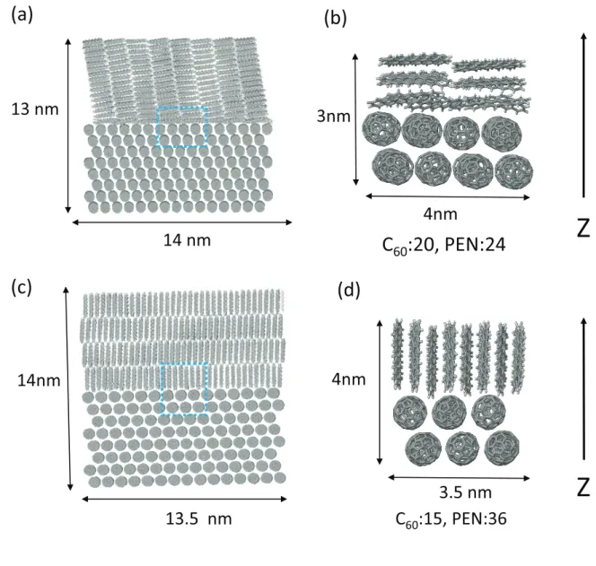
and their local interface regions including 2,000 atoms were treated quantum mechanically by the excited state method, with electrostatic embedding of the remaining molecules. Therefore, the structure disorder, electronic polarization, and charge delocalization effects are fully taken into account in the excited state calculations. As representative interfacial morphologies, we compared the edge-on and face-on configurations of PEN/C60interfaces as two-limiting cases, as illustrated
in Fig. 1. We characterize the excited states in terms of the electron-hole separation, extent of delocalization, and the absorption intensities. In particular, we highlight the importance of hy-bridization among PEN excited states and ICT states in forming optically-bright delocalized states, which enable long-range photoinduced electron transfer.
II. METHODOLOGIES
A. Modeling of atomic structures
The structural models of the C60(111)/PEN interface in Fig. 1 were prepared in the following
stages; (I) A supercell structure of FCC C60 was prepared, in which the [111], [2¯1¯1], and [01¯1]
directions were chosen for the edge directions of the periodic (orthorhombic) simulation cell. (II) A layered domain for the PEN thin film40was connected with the C60(111) surface in the edge-on
or face-on orientation. The prepared edge-on and face-on interface structures contain approxi-mately 9.5×10⁵ and 6.4×10⁶atoms in the periodic simulation cells, respectively. The edge length
in the [2¯1¯1] or [01¯1] direction are approximately 2 × 10 nm. Because the lattice mismatch is in-evitable for the interfaces between incommensurate C60and PEN crystalline structures, the large
edge lengths of the periodic simulation cell were used so as to reduce the lattice mismatch between the C60 and the PEN regions. The resultant interface structures have narrow spare spaces in the
C
60:20, PEN:24
(c)
(d)
(a)
C
60:15, PEN:36
Z
Z
(b)
14 nm
13 nm
3nm
4nm
4nm
14nm
3.5 nm
13.5 nm
FIG. 1: Atomistic structures of the (a) face-on and (c) edge-on interfaces included in the calculations. (b)(d) Local interface structures treated quantum-mechanically by the excited-state method.
[01¯1] direction. (III) A molecular dynamics simulation was carried out for the prepared interface structure at a temperature of 300 K for a simulation time of 10 ps; a structure optimization was carried out in the steepest descent algorithm. The molecular dynamics simulation package GRO-MACS41was used with the general AMBER force field (GAFF) model.42The resultant structures do not contain the spare spaces.
From the obtained bilayer heterojunction structures, the 13 × 14 × 13 nm3 and 13 × 13.5× 14 nm3regions were extracted from the face-on and edge-on configurations, respectively. The
ex-tracted face-on and edge-on configuration of the PEN/C60structure approximately include 1.8×10⁵
atoms and are shown in Fig. 1 (a) and (c), respectively. In these structures, we included molecules whose all atoms are inside the regions. The local interfacial regions, as evident in Fig. 1 (b) and (d), were treated quantum mechanically by the excited state method, with electrostatic potential from remaining molecules. Those local structure approximately contains 2,000 atoms with di-mensions of 3× 4 × 3 × nm3 for the face-on configuration and 3× 3.5 × 4 nm3 for the edge-on
configuration.
B. Ab initio excited-state calculations
Correct determinations of the electronic structure at organic heterojunctions remain a chal-lenging task, because charge delocalization and electronic polarization effects must be consid-ered. In addition, a large number of excited states must be calculated to fully characterize the excited state manifold. In earlier theoretical studies, a tight-binding Hamiltonian43–45 was used
to model the electronic structures. Herein, we carry out all-electron excited-state calculations for local interface structures, with all other molecules being treated as the external point charges. We have recently developed the fragment-based46,47excited-state method,48which is suitable for
treat-ing large molecular systems. The method is based on the multilayer fragment molecular orbital (FMO) method,49,50 FMO-linear combination of molecular orbital method,51 and the transition
density fragment interaction-transfer integral method.52
The fragment-based theory writes an excited-state wave function of the whole system (|Ψ⟩) as a superposition of diabatic states for intramolecular local excitations (LEs) and the intermolecular charge-transfer (CT) excitations.48 The diabatic LE state indicates a bound electron-hole pair lo-calized on a single molecule, whereas the diabatic CT state represents an intermolecular CT state comprising a localized electron and a localized hole on different molecules. The delocalization effects are taken into account by calculating matrix elements among diabatic states. For exam-ple, excitonic couplings52,53 determine the LE-LE matrix elements, resulting in the formation of
Frenkel exciton states. Transfer integrals (TIs)54,55 are responsible for the LE-CT and CT-CT
ma-trix elements, leading to charge delocalization. The adiabatic excited states of the total system are obtained by solving an eigenvalue problem, Hc = cE, where H is the excited-state Hamiltonian
represented in the diabatic states, and c denotes coefficients for the diabatic states. Details of the computation of the Hamiltonian matrix elements are found elsewhere.48
The excited-state wavefunction of the PEN/C60 interfaces were written as
|Ψ⟩ =Xck|LEk(C)⟩ + X ck|CTk(C−P+)⟩ + X ck|LEk(P)⟩ + X ck|CTk(P−P+)⟩ , (1) where |LEk(C)⟩ and |LEk(P)⟩ are intramolecular first excited states for C60 and PEN molecules,
respectively. We considered the highest-occupied molecular orbitals (HOMOs) and the lowest-unoccupied molecular orbitals (LUMOs) to construct the CT states;|CT(C−P+)⟩ denotes an ICT state comprising an hole on an HOMO of a PEN molecule and an electron on a LUMO, LUMO+1, or LUMO+2 of a C60molecule. Note that three degenerate LUMOs of C60molecules were
consid-ered for defining the intermolecular CT states. The intermolecular CT states within PEN molecules |CT(P−P+)⟩ were also included because of the substantial CT character in low-lying PEN excited
states.56–58With those diabatic states, the singlet excited-state Hamiltonian matrix element is writ-ten as H = HC−C HC−ICT HC−P
HICT−C HICT−ICT HICT−P
HP−C HP−ICT HP−P , (2)
where HC−C is C60-C60 block of the excited-state Hamiltonian, HICT−ICT is a ICT-ICT block, and
HP−P block is a PEN-PEN block. The excited states of the face-on and edge-on configurations of PEN/C60interfaces (Fig. 1 (b) and (d)) were obtained by the FMO at the configuration interaction
single (CIS)50,59/6-31G** level, using a locally-modified version of the ABINIT-MP program.47,60 The surrounding molecules included in Fig. 1 (a) and (c) were treated as external atomic point charges, where Mulliken atomic charges obtained from isolated PEN or C60 molecule were used.
We did not consider the self-consistency between the QM electron density and MM point charges. Although the induced polarization effects in the MM region cannot be included by this treatment, the dominant contributions from the MM region are the long-range Coulomb interactions arising from permanent multipole moments of molecules. Therefore, we believe that the neglect of the self-consistency of the MM point charges do not significantly alter the excited-state results. Further details of the excited-state calculations are provided in the supporting information.
Diagonal elements of excited-state Hamiltonian obtained at the CIS level were corrected as fol-lows. Although electronic couplings are qualitatively described at the CIS level, the excitation en-ergies (i.e., diagonal elements of the excited-state Hamiltonian) are substantially overestimated.61
Here, after calculating the Hamiltonian matrix elements of the PEN/C60interfaces, we added
cor-rection terms to the diagonal elements. The corcor-rection terms were defined as the difference be-tween CIS/Hartree-Fock (HF) results and a reference theory. As the reference theory, we used Kohn-Sham (KS) density functional theory (DFT) with time-dependent density functional theory within the Tamm-Dancoff approximation (TDA), in combination with the ωB97XD functional62
with the range separation parameter optimized for the pentacene/C60complex.31Differences in the
excitation energy, HOMO energy, and LUMO energy between TDA/KS and CIS/HF were com-puted for single molecules, and the results were used as correction terms for diagonal elements of the excited-state Hamiltonian. The single molecular calculations were performed using the Gaussian09 software,63and the results are presented in the supporting information.
III. RESULTS
Diagonalization of the excited-state Hamiltonian in the face-on or edge-on configurations gives rise to more than 2,000 singlet excited states. Figure 2 shows the ICT character versus the exci-tation energy for the excited states. Here, the ICT character of each excited state is quantified by
PICT= P
k|⟨CTk(C−P+)|ΨA⟩|2: A state with PICT = 1.0 is exclusively composed of the ICT states, while that with PICT = 0.0 is a PEN or C60excited state without any ICT contributions.
A. Effects of interfacial morphologies on the low-lying ICT states
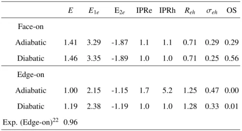
We begin our discussion with the lowest ICT states in the face-on and edge-on configurations. Among the ICT-state manifold, the lowest state is most important because its energy can be di-rectly determined from photoluminescence or electroluminescene spectra; moreover, it didi-rectly correlates with the open-circuit voltage value.3,64 Table I shows the excitation energies and
wave-function properties of the lowest ICT states. The corresponding values of the lowest diabatic ICT state are also shown for comparison. To gain deep insight into the energetics, the ICT energies were decomposed into the one-electron and two-electron contributions, E = E1e+ E2e. The
one-electron contribution is the orbital energy difference between the LUMO and HOMO, whereas the two-electron contribution is the Coulomb attraction between the electron and hole wave functions. The calculated ICT energies of the adiabatic states in the face-on and edge-on configurations are 1.41 and 1.00 eV, respectively, indicating the considerable influence of interface packing
struc-1.2 1.6 2.0 2.4 2.8 3.2 3.6 4.0 0.0 0.2 0.4 0.6 0.8 1.0 Energy (eV) (a) Face−on 0.8 1.2 1.6 2.0 2.4 2.8 0.0 0.2 0.4 0.6 0.8 1.0 Energy (eV)
Pop. of Interfacial CT (eV) (b) Edge−on
FIG. 2: ICT character of excited states of (a) edge-on and (b) face-on configurations of PEN/C60interfaces
tures.
To understand the morphology effects on the energetics, we first focus on the diabatic ICT energies. E1eand E2e of the localized ICT states are 3.35 and−1.89 eV, respectively, for the
face-on cface-onfiguratiface-on and are 2.38 and−1.19 eV, respectively for the edge-on configurations. On one hand, the difference in the E1e dominantly arises from the pentacene quadrupole moments, which
destablize/stablize the electron wave function on neighboring C60molecules in the face-on
/edge-on c/edge-onfigurati/edge-ons.25 On the other hand, E2e corresponds to the electron-hole Coulomb attraction,
and its magnitude is determined by the center-of-mass distance between C60 and PEN molecules.
As a result of two factors, the localized ICT energy in the edge-on configuration (1.19 eV) is lower than that in the face-on configuration (1.46 eV).
TABLE I: Excitation Energies (E/eV), Their One-electron (E1e) and Two-electron Contributions (E2e),
In-verse Participation Ratio of Electron and Hole Wave Functions (IPRe and IPRh), Electron-Hole Separations (Reh/nm), Standard Deviation of Electron-Hole Separation (σeh/nm), and Oscillator Strength (OS), for the
Face-on and Edge-on Configurations
E E1e E2e IPRe IPRh Reh σeh OS Face-on Adiabatic 1.41 3.29 -1.87 1.1 1.1 0.71 0.29 0.29 Diabatic 1.46 3.35 -1.89 1.0 1.0 0.71 0.25 0.56 Edge-on Adiabatic 1.00 2.15 -1.15 1.7 5.2 1.25 0.47 0.00 Diabatic 1.19 2.38 -1.19 1.0 1.0 1.28 0.33 0.01 Exp. (Edge-on)22 0.96
by the TIs among C60 molecules and/or hole TIs among PEN molecules, accompanied by the
delocalization of electron and/or hole wave functions. Here, inverse participation ratios (IPRs) were introduced to quantify the number of molecules where an electron or hole wave function is distributed. In the face-on configurations, the ICT energies does not change between the adiabatic and diabatic states. This is because the adiabatic ICT wave function is predominantly composed of the one C60-PEN pair, as evident from their electron IPR (IPRe) and hole IPR (IPRh). By contrast,
in the edge-on configuration the adiabatic ICT energy is decreased than the diabatic one. The IPRe and IPRh in the edge-on configuration are 1.7 and 5.2, respectively; the electron and hole wave functions are approximately delocalized over two C60 and five PEN molecules, respectively. By
comparing the E1eand E2ebetween adiabatic and diabatic ICT states in the edge-on configuration,
we found that the charge delocalization effect reduces the one-electron contribution but leaves the two-electron contribution unchanged. The reduction of the low-lying ICT energies in the edge-on configuration is due to the decrease in the orbital energy difference by the charge delocalization.
Here, we rationalize the effect of the interfacial morphologies on the hole delocalization. In general, the extent of delocalization is more enhanced by larger electronic couplings and smaller energy variation of composite states. In this study, the effects of interfacial morphology on the
charge delocalization is ascribed predominantly to the energy variation among strongly-interacting ICT states. In the face-on configuration, the stacking direction of PEN molecules runs perpendic-ular to the interface. As shown in the supporting information, the hole TIs of stacked PEN pairs are considerably large (> 100 meV), and the hole wave function can be delocalized over the PEN stacks. However, the hole delocalization along the stacks increases the excitation energy, because the adiabatic wave function becomes composed of higher-energy long-range ICT states (ICT states with large electron-hole separation). That is, the hole delocalization in the face-on configuration is suppressed by the considerable energy variations among ICT states. By contrast, the PEN stacks run parallel to the interface in the edge-on configuration, and the delocalization over the stack does not increase the electron-hole separation. The lowest ICT states in the edge-on interface can be delocalized without being mixed with higher-energy states.
Having investigated the charge delocalization effects, we now focus on the electron-hole sep-aration. The electron-hole separation was defined as the center-of-mass distance between the negative and positive charge densities. The extent of delocalization was quantified by the variance of the electron-hole separation. The average (Reh) and standard deviation (σeh) of the electron-hole distance of the lowest ICT states are shown in Table I. Earlier studies have suggested that the charge delocalization decreases electron-hole electrostatic interactions and thus increases the electron-hole separation.45,65We therefore expected larger IPRs andσ
ehto correlate with increased
Reh. However, irrespective of the larger IPRh andσeh of the adiabatic state in the edge-on config-uration, Reh does not change between diabatic and adiabatic wave functions. Because the lowest ICT states are composed of short-range ICT states whose Rehare similar to each other, the charge delocalization does not alter the center-of-mass distance between the electron and hole wave func-tions. Although the delocalization in the direction perpendicular to the interface leads to increased
Reh, it also increases the excitation energy. Such states do not appear as low-lying states in the excited-state manifold. The reduction of the low-lying ICT energies by the charge delocalization is consistent with recent experimental studies, where lowering of the ICT energies was found to be correlated with higher structural order.38,39
B. Characterization of CT-state manifold in the edge-on configuration
In this subsection, we characterize the ICT state manifold of the edge-on configuration. As shown in Fig 2 (b), some of states are not pure ICT states because of the hybridization with the PEN excited states. Previous theoretical studies have also reported the hybridization of donor LE states (or Frenkel exciton states) with ICT states.29,44,45 Herein, we discuss that the hybridization
between PEN excited states and ICT states leads to the formation of delocalized ICT states which enable long-range photoinduced electron transfer.
We begin by considering pure PEN and pure ICT states without hybridization. To this end, the PEN-PEN (HP−P) and ICT-ICT (HICT−ICT) blocks of the excited-state Hamiltonian were separately diagonalized without their electronic couplings. In Fig. 3 (a), the excitation energies as a function of Reh are shown for pure PEN and pure CT states. The PEN state manifold is composed of LE-dominant states at 1.5–2.5 eV and CT-dominant states above the LE-dominant states. The ICT-state manifold comprises the short-range ICT state in the energy region smaller than 1.4 eV and long-range ICT states above the short-range ICT state. As shown later, the long-range ICT states are more dense than the low-lying short-range ICT states.
Now we turn to the adiabatic excited states of the total PEN/C60system. Here, adiabatic excited
states were categorized according to their PICT values: (1) the PEN-dominant state (PICT < 0.2), (2) ICT-dominant states (PICT > 0.8), and (3) hybridized states (0.2 < PICT <0.8). In Fig. 3 (b) and (c), the Reh andσehfor three groups are shown in different colors. Regarding the ICT-dominant states, relatively localized short-range ICT states coexist with delocalized ICT states in the higher-energy region. The coexistence of the localized and delocalized ICT states is also supported by the results of a previous theoretical study on the bulk heterojunction device.45However, a recent experimental
study on the bulk heterojunction device has suggested that the extent of ICT delocalization is not sensitive to the excitation energy.16 Our study employing the bilayer heterojunction structures clearly indicates the substantial delocalization gradient in the excited-state manifold.
The PEN-ICT hybridization effects significantly change the excited-state character. Compared to the pure ICT states, the hybridization decreases Reh, but increasesσeh. Thus, the hybridized ICT states with an admixture of PEN states are more delocalized than the ICT-dominant states. The enhancement ofσeh is ascribed to the electron delocalization over both PEN and C60 molecules;
the superposition of a PEN state and ICT state results in the electron wave function extending over PEN and C60 molecules. The presence of the delocalized electron wave functions across the D/A
interface promotes efficient charge separation, enhancing long-range electron transfer.66
To further investigate the delocalization of electron wave functions and their roles in the charge separation, the delocalization length along the direction perpendicular to the D/A interface was calculated. Here, the second moments of electron wavefunction along the Z direction, σ2e,Z = ⟨Ψ (ze− Ze)2 Ψ⟩ were calculated, where ze is the Z-component of the electron position operator, and Z = ⟨Ψ ze Ψ⟩. As seen in Fig. 3 (d), the electron wave functions of the hybridized states can be significantly delocalized along the Z direction. The hybridized ICT states, with their electron wave functions extending across D/A interfaces, can mediate optically-bright PEN excited states and charge-separated states.
The PEN-ICT hybridization also alters the absorption of the ICT states. In general, CT states have vanishing oscillator strengths (OSs) because of relatively small overlap between the electron and hole wave functions. However, the ICT states can borrow OS from the optically-bright states via their hybridization. Figure 4 (a) shows the absorption spectrum of pure PEN states, as well as the density of pure ICT states, which comprises sparse short-range ICT in the lower energy region and dense long-range ICT states at approximately 1.8 eV. The absorption region of the PEN states is overlapped with that of the dense long-range ICT state manifold. As a result of hybridization with optically-bright PEN states, the ICT-dominant and hybridized states have significant absorp-tion intensities (Fig. 4). The absorpabsorp-tion intensity of the PEN-dominant states at approximately 1.8 eV is considerably decreased; most of the OSs of PEN states contribute as the CT-dominant or hybridized states. These results suggest that at D/A interfaces donor excited states cannot be distinguished from the ICT states.
The emergence of the optically-bright delocalized ICT state is confirmed by showing the cor-relation betweenσeh and OS in Fig. 5. Some of hybridized ICT states can have considerable OSs, by borrowing them from the PEN states. The visualization of such a representative delocalized ICT state is also shown. Figure 6 displays the electron and hole wave functions, which constitute the delocalized ICT state, as well as the excitation energy and wave function properties. Both elec-tron and hole wave functions are primary distributed among PEN molecules, and the elecelec-tron-hole overlap makes this state optically bright. The part of the electron wave function is also distributed over the C60molecules, thereby, increasing theσeh andσe,Zvalues.
Finally, we briefly comment on the effects of interfacial morphologies on the PEN-ICT hy-bridizations. It is expected that the PEN-ICT hybridization is more significant in the face-on configuration, because of the stronger electron TIs among PEN and C60molecules. Nevertheless,
according to the PEN-C60 electron TIs shown in the supporting information, the distributions of
electron TIs do not significantly change between the face-on and the edge-on configurations. A noticeably difference between the edge-on and the face-on configurations is found in the overlap between PEN absorption states and the density of ICT states. The ICT states are more stabilized in the edge-on configuration; hence, the density maximum of ICT state manifold is located at ap-proximately 1.8 eV. Conversely, the ICT states are destabilized in face-on configurations, and the PEN absorption region is overlapped with the sparse density of short-range ICT states. The direct optical transition to the delocalized ICT states is more pronounced in the edge-on configuration, because of the energy resonance between the PEN absorption and the dense long-range ICT states.
1.0 1.5 2.0 2.5 3.0 3.5 4.0 4.5 0.0 0.5 1.0 1.5 2.0 2.5 3.0 Energy (eV) Reh (nm) (a) PEN ICT 1.0 1.5 2.0 2.5 0.0 0.5 1.0 1.5 2.0 2.5 3.0 Energy (eV) Reh (nm) (b) PEN-dominant ICT-dominant Hybridized 1.0 1.5 2.0 2.5 0.5 1.0 1.5 σeh (nm) (c) 1.0 1.5 2.0 2.5 0.2 0.4 0.6 0.8 1.0 σe,Z (nm) (d)
FIG. 3: (a) Excitation energy versus electron-hole separation (Reh) for pure PEN states and pure ICT states
of the edge-on configuration. Excitation energy versus (b) Reh, (c)electron-hole delocalization (σeh), and (d)
electron delocalization along the Z direction (σe,Z) for adiabatic excited states of the edge-on configuration.
In (b)–(d), the PEN-dominant, ICT-dominant, and hybridized state are plotted in red, green, and blue, respectively.
0 2 4 6 8 10 12 14 1.0 1.5 2.0 2.5 0 20 40 60 80 100 120
Absorption (arb. unit.) Number of ICT States
Energy (eV) (a) PEN Abs. ICT DOS 10-4 10-3 10-2 10-1 100 101 1.0 1.5 2.0 2.5
Absorption (arb. unit.)
Energy (eV) (b)
PEN-dom. ICT-dom. Hybridized
FIG. 4: (a) The absorption spectrum of pure PEN states and the density of pure ICT states. (b) The absorp-tion spectra of PEN-dominant, ICT-dominant, and hybridized states in the edge-on configuraabsorp-tion.
10-2 10-1 100 0.6 0.8 1.0 1.2 1.4 1.6 OS σeh (nm) ICT-dom. Hybridized
FIG. 5: Oscillator strength (OS) versus electron-hole delocalization (σeh) for ICT-dominant (green) and
hybridized (blue) states in the edge-on configuration.
E = 2.00 eV
Reh= 0.38 nm, ʍeh= 1.48 nm ʍe,Z= 0.81 nm, OS = 0.94
Electron Hole
FIG. 6: The visualization of the electron (red) and hole (blue) wave functions, which constitute the delocal-ized ICT state. The excitation energy and wave function properties are also presented.
IV. DISCUSSION
Recent experimental studies have pointed to the effect of the molecular orientations and bulk morphologies on the energetics of ICT states.6,38,39 The important factors contributing to the ICT energies are the electrostatics and polarization effects on the HOMO and LUMO energy lev-els, which have been addressed by the microelectrostatic model25,67 and by photoelectron
spec-troscopy.68 Our first-principles study employing the extended bilayer heterojunction successfully describes the interface-dependent ICT energy shifts. Moreover, we found that the delocalization of low-lying ICT states strongly depend on the interfacial morphology. Our results support the earlier first-principles investigation by Yang et al.29 and extend their conclusion in such a that the
ICT states can be significantly delocalized even in the presence of structure disorder inherent in the D/A interface, highlighting the interplay of the electronic polarization and charge delocalizatioin in the ICT energetics.
In this study, we have separately treated the face-on and edge-on configurations as two limiting cases. Because we aimed to prepare the ideal face-on or edge-on orientation, the bilayer hetero-junction structures were modeled by jointing two crystal structures. By contrast, the earlier MD simulation study by Fu et al.27 has reported more disordered C60/PEN interfaces. They observed
that in the presence of terrace the deposition of C60molecules on PEN surface leads to the
consid-erable structural disorder and the intermixing between among C60 and PEN molecules, resulting
in the coexistence of the face-on and edge-on oriented C60-PEN pairs.27However, the coexistence
of the face-on and the edge-on configurations in the pentacene/C60bilayer heterojunction has been
challenged by Brigeman et al.22on the basis of the X-ray diffraction measurements. Although they have observed two main absorption peaks in the EQE spectrum, they ascribed it from the coex-istence of two pentacene polymorphs.22The extent of disorder in the interfacial structures is still
an open problem. Even if our structural models may not be strictly compared with the experimen-tal structure, the present calculations for the two-limiting configurations provide the microscopic insight into the impact of interfacial morphologies on excited states.
The hybridization between donor excited states and ICT states have been observed in earlier theoretical studies.29,44,45 In particular, Ma and Troisi have discussed that long-range ICT states
can be directly generated by optical excitation, because of the intensity borrowing and the dense long-range ICT states.44 Consistent with their findings, we confirmed the role of PEN-ICT
energy resonance between the donor absorption states and the dense ICT manifold results in di-minished absorption intensity of PEN-dominant states and in the subsequent emergence of the optically-bright delocalized ICT states. Our results may rationalize the experimentally observed ultrafast charge separation (< 100 fs) in the presence of large fullerene clusters.17–19The number of ICT states increases with increasing size of fullerene aggregates, providing dense long-range ICT states. Therefore, the ultrafast charge separation observed in the experiments can be interpreted as the direct long-range electron transfer via delocalized electron wave functions.
In previous experimental studies, the ICT absorption and emission spectra have been interpreted in terms of the Marcus theory.3,5,6,69 In this model, an ICT spectrum is represented by one or several Gaussian peaks representing ICT states, broadened by reorganization energies. Along with this line, the ICT absorption of the edge-on configuration of the PEN/C60 heterojunction
system has been measured from the polarized EQE subtraction method introduced by Brigeman et al.22 The ICT spectrum was fitted to two distinct Gaussian peaks at 0.96 and 1.30 eV, with
their reorganization energies as 0.20 and 0.04 eV, respectively. According to our excited-state calculations, the absorption of the ICT-dominant states were obtained in the range of 1.0–1.5 eV (Fig 4 (a)). Although the calculated ICT absorption is broadened by contributions of many ICT-dominant states without regard to the reorganization energies, the spectrum compares well with the experimental ICT spectrum.22 It follows that the physical origins of the spectral broadening
should be carefully analyzed even if the Marcus theory can well describe the spectral lineshape. Recent investigations of alternative models to fit ICT spectra are summarized in a recent review.6
We note that the following points should be revisited in future works. First, the triplet excited states were not considered in this article. PEN crystals70are known to exhibit efficient singlet fis-sion, and the charge separation can also occur from the triplet excited states of PEN molecules.33,34
Although the energy of triplet ICT states is almost equivalent to those of singlet ICT states because of negligible electron-hole exchange interactions,32their hybridization with PEN triplet states may be different. Second, we note that the present excited-state calculations48 overestimate the
long-range ICT energies. Because our calculations do not fully account for the electronic polarization induced by CT excitations, they overestimate the energy difference among the short-range ICT and long-range ICT states. This overestimation of the long-range ICT energies would somewhat affect the PEN-ICT hybridizations. Third, charge photogeneration should be understood as a dynamical process, and the role of delocalized ICT states in the excited-state dynamics remains to be eluci-dated. A real-time simulation of the charge separation dynamics will be achieved by combining
a large-scale numerical technique71–73 with a quantum dynamics theory,74–76 which is left for a future study.
V. CONCLUSION
In this article, we investigated the singlet excited states of PEN/C60bilayer heterojunction
struc-tures, applying the ab initio excited-state method to atomistic structures modeled by the MD sim-ulations. We have successfully reproduced the energetics of experimentally-obtained ICT states. The excited-states of the PEN/C60interfaces were characterized in terms of the electron-hole
sep-aration, electron-hole delocalization, and absorption intensities. We found that the PEN-ICT hy-bridization results in the formation of delocalized ICT states, with electron wave functions ex-tending across the PEN/C60 interface. In addition, we confirmed the delocalized ICT states can
become optically bright and thus enable the long-range photoinduced electron transfer, which may rationalize the experimentally-observed ultrafast charge separations.17–19
From a computational standpoint, we demonstrated the large-scale excited state calculations for the extended bilayer heterojunction structures based on the recently-developed fragment-based method.48 Because of its parallel efficiency, our fragment-based method is particularly useful for
treating large and disordered molecular aggregates, where the combined effect of charge delo-calization and electronic polarization plays an important role. Moreover, our method allows for efficient computations of a large number of states in organic aggregates; this feature is essential for theoretical investigations of OSCs, because the charge separation process cannot be under-stood by considering just one or a couple of representative excited states. Further applications to other materials are straightforward and will enable us to explore a correlation between interfacial morphologies and optoelectronic processes, which is essential for designing and improving novel organic devices.
Supporting Information
Conflicts of interest
The author declares no competing financial interest.
Acknowledgments
T.F. and M.K.A. thank the financial support of the Building of Consortia for the Development of Human Resources in Science and Technology, MEXT, Japan. The authors thank Yukiya Abe and Mayumi Kuno (Tottori University) for collaboration in the development of the structure prepa-ration softwares for the interfaces. The present research was partially supported by KAKENHI projects (16KT0016, 17H02828) and Priority issue 7 for the Post-K computer. The excited-state calculations in this work were done using the facilities of the Supercomputer Center, the Institute for Solid State Physics, the University of Tokyo. Several calculations were carried out on the K computer (project code:hp170147) and Oakforest-PACS (project code:jh170058).
∗ Electronic address: [email protected]
1 T. M. Clarke and J. R. Durrant, Chem. Rev., 2010, 110, 6736–6767. 2 O. Ostroverkhova, Chem. Rev., 2016, 116, 13279–13412.
3 K. Vandewal, K. Tvingstedt, A. Gadisa, O. Ingan¨as and J. V. Manca, Phys. Rev. B, 2010, 81, 125204. 4 J. Benduhn, K. Tvingstedt, F. Piersimoni, S. Ullbrich, Y. Fan, M. Tropiano, K. A. McGarry, O. Zeika,
M. K. Riede, C. J. Douglas, S. Barlow, S. R. Marder, D. Neher, D. Spoltore and K. Vandewal, Nature
Energy, 2017, 2, 17053.
5 K. Vandewal, Annu. Rev. Phys. Chem., 2016, 67, 113–133.
6 Y. L. Lin, M. A. Fusella and B. P. Rand, Adv. Energy Mater., 2018, 8, 1702816. 7 F. Gao and O. Inganas, Phys. Chem. Chem. Phys., 2014, 16, 20291–20304.
8 S. Few, J. M. Frost and J. Nelson, Phys. Chem. Chem. Phys., 2015, 17, 2311–2325.
9 S. H. Park, A. Roy, S. Beaupr´e, S. Cho, N. Coates, J. S. Moon, D. Moses, M. Leclerc, K. Lee and A. J.
Heeger, Nat. Photonics, 2009, 3, 297–302.
10 T. G. van der Hofstad, D. Di Nuzzo, M. van den Berg, R. A. Janssen and S. C. Meskers, Adv. Ene. Mater.,
11 G. D’Avino, S. Mothy, L. Muccioli, C. Zannoni, L. Wang, J. Cornil, D. Beljonne and F. Castet, J. Phys.
Chem. C, 2013, 117, 12981–12990.
12 K. Vandewal, S. Albrecht, E. T. Hoke, K. R. Graham, J. Widmer, J. D. Douglas, M. Schubert, W. R.
Mateker, J. T. Bloking, G. F. Burkhard, A. Sellinger, J. M. J. Fr´echet, A. Amassian, M. K. Riede, M. D. McGehee, D. Neher and A. Salleo, Nat. Mater., 2014, 13, 63–8.
13 A. Bakulin, A. Rao, V. G. Pavelyev, P. H. M. van Loosdrecht, M. S. Pshenichnikov, D. Niedzialek,
J. Cornil, D. Beljonne and R. H. Friend, Science, 2012, 335, 1340.
14 A. E. Jailaubekov, A. P. Willard, J. R. Tritsch, W.-L. Chan, N. Sai, R. Gearba, L. G. Kaake, K. J.
Williams, K. Leung, P. J. Rossky and X.-Y. Zhu, Nat. Mater., 2013, 12, 66–73.
15 G. Grancini, M. Maiuri, D. Fazzi, a. Petrozza, H.-J. Egelhaaf, D. Brida, G. Cerullo and G. Lanzani, Nat.
Mater., 2013, 12, 29–33.
16 Z. Guan, H.-W. Li, J. Zhang, Y. Cheng, Q. Yang, M.-F. Lo, T.-W. Ng, S.-W. Tsang and C.-S. Lee, ACS
Appl. Mater. Inter., 2016, 8, 21798–21805.
17 S. G´elinas, A. Rao, A. Kumar, S. L. Smith, A. W. Chin, J. Clark, T. S. van der Poll, G. C. Bazan and
R. H. Friend, Science, 2014, 343, 512–516.
18 A. C. Jakowetz, M. L. B′′ohm, J. Zhang, A. Sadhanala, S. Huettner, A. A. Bakulin, A. Rao and R. H.
Friend, J. Am. Chem. Soc., 2016, 138, 11672–11679.
19 A. C. Jakowetz, M. L. B´’ohm, A. Sadhanala, S. Huettner, A. Rao and R. H. Friend, Nat. Mater., 2017,
16, 551.
20 K. Tvingstedt, K. Vandewal, A. Gadisa, F. Zhang, J. Manca and O. Inganas, J. Am. Chem. Soc., 2009,
131, 11819–11824.
21 B. Bernardo, D. Cheyns, B. Verreet, R. Schaller, B. Rand and N. Giebink, Nature communications, 2014,
5, 3245.
22 A. N. Brigeman, M. A. Fusella, Y. Yan, G. E. Purdum, Y.-L. Loo, B. P. Rand and N. C. Giebink, Adv.
Energy Mater., 2016, 6, 1601001–n/a.
23 M. A. Fusella, A. N. Brigeman, M. Welborn, G. E. Purdum, Y. Yan, R. D. Schaller, Y. L. Lin, Y.-L. Loo,
T. V. Voorhis, N. C. Giebink and B. P. Rand, Adv. Energy Mater., 2018, 8, 1701494.
24 J.-L. Br´edas, J. E. Norton, J. Cornil and V. Coropceanu, Acc. Chem. Res., 2009, 42, 1691–1699.
25 S. Verlaak, D. Beljonne, D. Cheyns, C. Rolin, M. Linares, F. Castet, J. Cornil and P. Heremans, Adv.
Funct. Mater., 2009, 19, 3809–3814.
27 Y.-T. Fu, C. Risko and J.-L. Br´edas, Adv. Mater., 2013, 25, 878–882.
28 T. Minami, S. Ito and M. Nakano, Int. J. Quantum. Chem., 2013, 113, 252–256.
29 B. Yang, Y. Yi, C.-R. Zhang, S. G. Aziz, V. Coropceanu and J.-L. Br´edas, J. Phys. Chem. C, 2014, 118,
27648–27656.
30 B.-C. Lin, B. T. Koo, P. Clancy and C.-P. Hsu, J. Phys. Chem. C, 2014, 118, 23605–23613. 31 Z. Zheng, J.-L. Br´edas and V. Coropceanu, J. Phys. Chem. Lett., 2016, 7, 2616–2621.
32 Z. Zheng, N. R. Tummala, Y.-T. Fu, V. Coropceanu and J.-L. Br´edas, ACS Appl. Mater. Inter., 2017, 9,
18095–18102.
33 W.-L. Chan, M. Ligges, A. Jailaubekov, L. Kaake, L. Miaja-Avila and X.-Y. Zhu, Science, 2011, 334,
1541–1545.
34 D. N. Congreve, J. Lee, N. J. Thompson, E. Hontz, S. R. Yost, P. D. Reusswig, M. E. Bahlke, S. Reineke,
T. Van Voorhis and M. A. Baldo, Science, 2013, 340, 334–337.
35 M. Yamamoto, Y. Nakayama, Y. Uragami, H. Kinjo, Y. Mizuno, K. Mase, K. R. Koswattage and H. Ishii,
e-J. Surf. Sci. Nanotech., 2015, 13, 59–64.
36 Y. Nakayama, Y. Mizuno, T. Hosokai, T. Koganezawa, R. Tsuruta, A. Hinderhofer, A. Gerlach, K. Broch,
V. Belova, H. Frank, M. Yamamoto, J. Niederhausen, H. Glowatzki, J. P. Rabe, N. Koch, H. Ishii, F. Schreiber and N. Ueno, ACS Appl. Mater. Inter., 2016, 8, 13499–13505.
37 K. R. Graham, G. O. N. Ndjawa, S. M. Conron, R. Munir, K. Vandewal, J. J. Chen, S. Sweetnam, M. E.
Thompson, A. Salleo, M. D. McGehee and A. Amassian, Adv. Energy Mater., 2016, 6, 1601211.
38 Y. L. Lin, M. A. Fusella, O. V. Kozlov, X. Lin, A. Kahn, M. S. Pshenichnikov and B. P. Rand, Adv.
Funct. Mater., 2016, 26, 6489–6494.
39 C. K¨astner, K. Vandewal, D. A. M. Egbe and H. Hoppe, Adv. Sci., 2017, 4, 1600331.
40 S. Schiefer, M. Huth, A. Dobrinevski and B. Nickel, J. Am. Chem. Soc., 2007, 129, 10316–10317. 41 H. J. Berendsen, D. van der Spoel and R. van Drunen, Comput. Phys. Commun., 1995, 91, 43–56. 42 J. Wang, R. M. Wolf, P. A. Kollman and D. A. Case, J. Comput. Chem., 2004, 25, 1157–1174. 43 H. Tamura and I. Burghardt, J. Am. Chem. Soc., 2013, 135, 16364–16367.
44 H. Ma and A. Troisi, Adv. Mater., 2014, 26, 6163–6167.
45 G. D’Avino, L. Muccioli, Y. Olivier and D. Beljonne, J. Phys. Chem. Lett., 2016, 7, 536–540.
46 The Fragment Molecular Orbital Method: Practical Applications to Large Molecular Systems, ed. D. G.
Fedorov and K. Kitaura, CRC Press, Boca Raton, FL, 2009.
16, 10310–10344.
48 T. Fujita and Y. Mochizuki, J. Phys. Chem. A, 2018, 122, 3886–3898.
49 D. G. Fedorov, T. Ishida and K. Kitaura, The Journal of Physical Chemistry A, 2005, 109, 2638–2646. 50 Y. Mochizuki, S. Koikegami, S. Amari, K. Segawa, K. Kitaura and T. Nakano, Chem. Phys. Lett., 2005,
406, 283–288.
51 S. Tsuneyuki, T. Kobori, K. Akagi, K. Sodeyama, K. Terakura and H. Fukuyama, Chem. Phys. Lett.,
2009, 476, 104–108.
52 K. J. Fujimoto, J. Chem. Phys., 2012, 137, 034101.
53 M. F. Iozzi, B. Mennucci, J. Tomasi and R. Cammi, J. Chem. Phys., 2004, 120, 7029–7040. 54 H. Kitoh-Nishioka and K. Ando, J. Chem. Phys., 2016, 145, 114103.
55 T. Fujita, Y. Haketa, H. Maeda and T. Yamamoto, Org. Electron., 2017, 49, 53–63. 56 R. Schuster, M. Knupfer and H. Berger, Phys. Rev. Lett., 2007, 98, 037402.
57 H. Yamagata, J. Norton, E. Hontz, Y. Olivier, D. Beljonne, J. L. Br´edas, R. J. Silbey and F. C. Spano, J.
Chem. Phys., 2011, 134, –.
58 S. Sharifzadeh, P. Darancet, L. Kronik and J. B. Neaton, J. Phys. Chem. Lett., 2013, 4, 2197–2201. 59 J. B. Foresman, M. Head-Gordon, J. A. Pople and M. J. Frisch, J. Phys. Chem., 1992, 96, 135–149. 60 T. Nakano, T. Kaminuma, T. Sato, Y. Akiyama, M. Uebayasi and K. Kitaura, Chem. Phys. Lett., 2002,
351, 475–480.
61 A. Dreuw and M. Head-Gordon, Chem. Rev., 2005, 105, 4009–4037.
62 J.-D. Chai and M. Head-Gordon, Phys. Chem. Chem. Phys., 2008, 10, 6615–6620.
63 M. J. Frisch, G. W. Trucks, H. B. Schlegel, G. E. Scuseria, M. A. Robb, J. R. Cheeseman, G. Scalmani,
V. Barone, B. Mennucci, G. A. Petersson, H. Nakatsuji, M. Caricato, X. Li, H. P. Hratchian, A. F. Iz-maylov, J. Bloino, G. Zheng, J. L. Sonnenberg, M. Hada, M. Ehara, K. Toyota, R. Fukuda, J. Hasegawa, M. Ishida, T. Nakajima, Y. Honda, O. Kitao, H. Nakai, T. Vreven, J. A. Montgomery, Jr., J. E. Peralta, F. Ogliaro, M. Bearpark, J. J. Heyd, E. Brothers, K. N. Kudin, V. N. Staroverov, R. Kobayashi, J. Nor-mand, K. Raghavachari, A. Rendell, J. C. Burant, S. S. Iyengar, J. Tomasi, M. Cossi, N. Rega, J. M. Millam, M. Klene, J. E. Knox, J. B. Cross, V. Bakken, C. Adamo, J. Jaramillo, R. Gomperts, R. E. Strat-mann, O. Yazyev, A. J. Austin, R. Cammi, C. Pomelli, J. W. Ochterski, R. L. Martin, K. Morokuma, V. G. Zakrzewski, G. A. Voth, P. Salvador, J. J. Dannenberg, S. Dapprich, A. D. Daniels, O. Farkas, J. B. Foresman, J. V. Ortiz, J. Cioslowski and D. J. Fox, Gaussian 09 Revision E.01, Gaussian Inc. Wallingford CT 2009.
64 J. Yao, T. Kirchartz, M. S. Vezie, M. A. Faist, W. Gong, Z. He, H. Wu, J. Troughton, T. Watson, D. Bryant
and J. Nelson, Phys. Rev. Applied, 2015, 4, 014020.
65 H. Tamura and I. Burghardt, J. Am. Chem. Soc., 2013, 135, 16364–16367. 66 D. Caruso and A. Troisi, Proc. Natl. Acad. Sci. USA, 2012, 109, 13498–13502.
67 F. Castet, G. D’Avino, L. Muccioli, J. Cornil and D. Beljonne, Phys. Chem. Chem. Phys., 2014, 16,
20279–20290.
68 H. Yoshida, K. Yamada, J. Tsutsumi and N. Sato, Phys. Rev. B, 2015, 92, 075145. 69 R. A. Marcus, J. Chem. Phys., 1956, 24, 966–978.
70 M. W. Wilson, A. Rao, J. Clark, R. S. S. Kumar, D. Brida, G. Cerullo and R. H. Friend, J. Am. Chem.
Soc., 2011, 133, 11830–11833.
71 J. Terao, A. Wadahama, A. Matono, T. Tada, S. Watanabe, S. Seki, T. Fujihara and Y. Tsuji, Nat.
Com-mun., 2013, 4, 1691.
72 T. Hoshi, Y. Akiyama, T. Tanaka and T. Ohno, J. Phys. Soc. Jpn., 2013, 82, 023710.
73 H. Imachi, S. Yokoyama, T. Kaji, Y. Abe, T. Tada and T. Hoshi, AIP Conf. Proc., 2016, 1790, 020010. 74 J. Huh, S. K. Saikin, J. C. Brookes, S. Valleau, T. Fujita and A. Aspuru-Guzik, J. Am. Chem. Soc., 2014,
136, 2048–2057.
75 N. P. D. Sawaya, J. Huh, T. Fujita, S. K. Saikin and A. Aspuru-Guzik, Nano Lett., 2015, 15, 1722–1729. 76 T. Fujita, S. Atahan-Evrenk, N. P. D. Sawaya and A. Aspuru-Guzik, J. Phys. Chem. Lett., 2016, 7,