令
和
元
年
度
修
士
論
文
非定常回転する風車の形状最適化のための数値
シミュレーションによる研究
指導教員
小林 春夫 教授
群馬大学大学院理工学府 理工学専攻
電子情報・数理教育プログラム
白 雪妍
contents
...2
Numerical Simulation for Optimization of the Shape of Unsteady Rotating Wind Turbine... 3
I. Research on the best shape of Savonius wind turbine... 3
1.Introduction... 3
2.Wind and wind turbines... 6
2.1 How much power is in the wind?... 6
2.2 Types of wind turbines...8
2.3 Horizontal Axis Wind Turbine... 10
2.4 Vertical Axis Wind Turbine...11
2.5 Lift Type and Drag Type Wind Turbine...12
2.6 Savonius Wind Turbine... 14
3. Numerical Methods... 16
3.1 Basic equation...16
3.2 Numerical solution...17
3.3 Computational domain and boundary condition...17
3.4 Torque calculation and wind turbine equation of motion...18
3.5 Steady and unsteady...21
4. Results... 23
5 Conclusion and Discussion... 28
Ⅱ. Researching for finding the influence of wind direction on two Darrieus-type wind turbines... 30
1. Introduction... 30
2.Theory and numerical method of wind turbine...32
2.1Dynamical model of the wind turbine... 32
2.2 Basic equations... 33 2.3 Numerical Solution... 34 2.4 Calculation of Torque... 34 2.5 Grid systems...35 2.6 Boundary condition...36 2.7 Calculation condition...36
3 Results and discussions... 37
4 Conclusion...38
References... 39
I. Research on the best shape of Savonius wind turbine... 39
Ⅱ.Researching for finding the influence of wind direction on two Darrieus-type wind turbines... 39
Research Achievements... 41
Numerical Simulation for Optimization of the
Shape of Unsteady Rotating Wind Turbine
I. Research on the best shape of Savonius wind turbine.
1.Introduction
The wind turbine is expected to be a candidate that is source of renewable energy and solves the global environmental problems associated with CO2 emission. The small wind turbines are easily introduced as local electric energy source equipment for residences in suburb. The present experimental study focuses on a small wind turbine which has accessible possibility of renewable energy.
Wind turbines are systems that harness the kinetic energy of the wind for useful power. Wind flows over the rotor of a wind turbine, causing it to rotate on a shaft. The resulting shaft power can be used for mechanical work, like pumping water, or to turn a generator to produce electrical power.
Wind turbines span a wide range of sizes, from small rooftop turbines generating less than 100 kilowatts up to large commercial wind turbines in the megawatt power range, many of which operate in large clusters called wind farms.
Wind turbines are manufactured in a wide range of vertical and horizontal axis. The smallest turbines are used for applications such as battery charging for auxiliary power for boats or caravans or to power traffic warning signs. Larger turbines can be used for making contributions to a domestic power supply while selling unused power back to the utility supplier via the electrical grid. Arrays of large turbines, known as wind farms, are becoming an increasingly important source of intermittent renewable
energy and are used by many countries as part of a strategy to reduce their reliance on fossil fuels. The wind had the "lowest relative greenhouse gas emissions, the least water consumption demands and the most favorable social impacts[1]" compared to photovoltaic, hydro, geothermal, coal and gas.
It is expected to have a distributed energy system combining small-scale energy sources such as solar power generation which can be easily installed on rooftop of public facilities, small-scale hydropower generation which can utilize agricultural water, and wind power generation. There are the following advantages in constructing the distributed energy system:
(1) Activation of regional industries
(2) power supply can be secured in each area even when trouble occurs in power supply from large-scale power supply.
(3) the power station and the demand area are need to be close. Therefore, the transmission system becomes smaller than the centralized energy system.
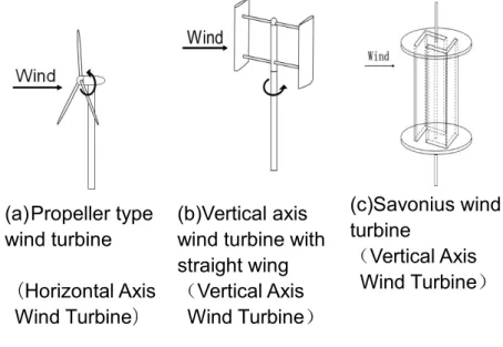
There are several types of wind turbines used in wind power generation as shown in Fig. 1. In large wind farms and offshore wind power generation, large propeller type wind turbine as shown in Fig. 1(a)are mainly used. For the distributed energy system, a small vertical axis type wind turbine shown in Fig. 1(b) and 1(c) is often used. Vertical axis type wind turbines are suitable for construction in the neighborhood of electric power demand sites (residential sites), but there are many problems, such as electricity generation is not enough. Since Japan has narrow land and complicated wind conditions, there are many situations where wind turbines developed in
advanced countries of wind power generation such as Europe, and wind turbine operation know-how accumulated can not be applied. In particular, small vertical axis type wind turbines are small in number of introduction, it is the present state that it does not become commercialization which is economically stable.
We aim at the development of a wind turbine simulator considering the complicated wind conditions in Japan aiming at the utilization of small wind turbines in distributed energy systems. In this study, the characteristics of the unsteady rotating Savonius wind turbine were verified by simulation, and the optimum shape was examined.
(a)Propeller type wind turbine (Horizontal Axis
Wind Turbine)
(b)Vertical axis wind turbine with straight wing (Vertical Axis Wind Turbine) (c)Savonius wind turbine (Vertical Axis Wind Turbine)
Fig. 1. Types of wind turbines
In many cases, the basic characteristics can be measured by rotating only one wind turbine at a constant angular velocity[2]. However, response characteristics to changes in wind speed are also important. Especially, when wind turbines are installed near the urban area where wind direction and wind speed are not stable, it is necessary to examine characteristics such as start, stop, acceleration and deceleration of wind turbines for the change of wind speed.
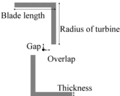
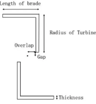
In this study, we investigated the characteristics of rotating wind turbines and investigated the time varying rotation in order to investigate the optimum wing shape. Fig. 2 is a sectional view of the Savonius wind turbine shown in Fig. 1(c). This time, five parameters (blade length, wind turbine radius, overlap, gap, blade thickness) are optimized.
Fig. 2. Cross section of Savonius wind turbines
2.Wind and wind turbines
2.1 How much power is in the wind?The power available in the wind, P, can be found from the following equation:
3
2 1 A V p
(2.1.1) where ρ is the density of the air, A is the capture area, and V is the wind speed. Wind speed increases with height above the ground, because of the earth’s boundary layer.
This effect is modeled using a power law relation:
) 10 ( 10 z V Vz (2.1.2)
where V is the wind speed at some heightz z (in meters), V10 is the wind speed
at 10 meters (the height often used for meteorological reporting of wind speed), and α is the power law exponent or index. α varies over a wide range, 0.1 to 0.6 depending on atmospheric conditions and the terrain near the wind turbine, but a value of 0.2 is common for wind turbine analysis.
For the example shown in Figure 4, the wind speed at 10 meter height is 15 m/s wind speed. At 20 meter height, the wind speed is 17.2 m/s and there is 0.94 MW of power available in the wind, for a 300 m2 capture area. (1 MW= 1 million Watts). At 60 meters, the wind speed is about 25 % higher, but the power is almost doubled at 1.8 MW.
Fig. 4. Wind Speed, Power and Height(300m² capture area)[3]
Not all of this power can be captured by a wind turbine, due to physical limits (e.g., Betz limit) as well as inefficiencies in the rotor, generator and gearboxes.
2.2 Types of wind turbines
Although there are many different wind turbine designs, they are broadly grouped in two categories based on the orientation of the axis of rotation: Horizontal Axis Wind Turbines, or HAWTS, the most common type of wind turbine, and Vertical Axis Wind Turbines, or VAWTS. Furthermore, they can be divided into a lift type that rotates using lift and a drag type that rotates using drag.
Fig.5. Classification of wind turbine type
(A)Horizontal axis wind turbine.[7]
(B)Vertical axis wind turbine.
2.3 Horizontal Axis Wind Turbine
Wind turbine has an upwind system in which the rotating surface of the rotor is located on the upwind side of the tower and a downwind system on the leeward side in the horizontal axis type.
Since the rotor is located on the windward side of the tower, it is not affected by the wind turbulence caused by the tower, and the upwind system is the mainstream of the current wind turbine in the upwind system. On the other hand, the downwind method has the feature that the yaw drive device for automatically adjusting the propeller direction to the wind direction is unnecessary. While in the U.S. wind turbine development stage, a downwind wind turbine is introduced. To the small wind turbine, although there are not many examples of applications, downwind wind turbines with large aircraft have also been developed in recent years.
Modern HAWTs usually feature rotors that resemble aircraft propellers, which operate on similar aerodynamic principles, i.e., the air flow over the airfoil shaped blades creates a lifting force that turns the rotor. The nacelle of a HAWT houses a gearbox and generator. HAWTs can be placed on towers to take advantage of higher winds farther from the ground.
The capture area of a HAWT, the area over which the sweeping blades can “capture” the wind, is given by
2 ) 2 ( 2 D A (2.3.1)
wind, to maximize power generation, so HAWTS require a means for alignment (yawing mechanism) so that the entire nacelle can rotate into the wind. On smaller wind turbines, a tail vane provides a “passive” yaw control. In large, grid-connected turbines, yaw control is active, with wind direction sensors and motors that rotate the nacelle.
2.4 Vertical Axis Wind Turbine
A vertical-axis wind turbines (VAWT) is a type of wind turbine where the main rotor shaft is set transverse to the wind (but not necessarily vertically) while the main components are located at the base of the turbine. This arrangement allows the generator and gearbox to be located close to the ground, facilitating service and repair. VAWTs do not need to be pointed into the wind, which removes the need for wind-sensing and orientation mechanisms.
There are two main types of VAWTs, the Savonius and the Darrieus. The Savonius operates like a water wheel using drag forces, while the Darrieus uses blades similar to those used on HAWTS. VAWTs typically operate closer to the ground, which has the advantage of allowing placement of heavy equipment, like the generator and gearbox, near ground level rather than in the nacelle. However, winds are lower near ground level, so for the same wind and capture area, less power will be produced.
Another advantage of a VAWT over the HAWT is that it doesn't require a yaw mechanism, since it can harness wind from any direction. This advantage is outweighed by many other disadvantages, including: time varying power output due
to variation of power during a single rotation of the blade, the need for guy wires to support the tower and the fact that Darrieus VAWTS are not self-starting like HAWTS.
2.5 Lift Type and Drag Type Wind Turbine
Airflow over any surface creates two types of aerodynamic forces— drag forces, in the direction of the airflow, and lift forces, perpendicular to the airflow. Either or both of these can be used to generate the forces needed to rotate the blades of a wind turbine. As a classification according to the working principle, wind turbines are divided into a lift type and a drag type.
Drag-based wind turbine
In drag-based wind turbines, the force of the wind pushes against a surface, like an open sail. In fact, the earliest wind turbines, dating back to ancient Persia, used this approach. The Savonius rotor is a simple drag-based windmill that you can make at home (Figure 7). It works because the drag of the open, or concave, face of the cylinder is greater than the drag on the closed or convex section.
Fig.7. Drag-based Wind Turbine Concept(Savonius Rotor)[4]
Lift-based Wind Turbines
More energy can be extracted from wind using lift rather than drag, but this requires specially shaped airfoil surfaces, like those used on airplane wings (Figure 8). The airfoil shape is designed to create a differential pressure between the upper and lower surfaces, leading to a net force in the direction perpendicular to the wind direction. Rotors of this type must be carefully oriented (the orientation is referred to as the rotor pitch), to maintain their ability to harness the power of the wind as wind speed changes.
Fig.8. Lift-based Wind Turbine Concept[4]
2.6 Savonius Wind Turbine
The Savonius wind turbine was invented by the Finnish engineer Sigurd Johannes Savonius in 1922.Savonius wind turbines are a type of vertical-axis wind turbine (VAWT), used for converting the force of the wind into torque on a rotating shaft.
The Savonius turbine is one of the simplest turbines. Aerodynamically, it is a drag-type device, consisting of two or three scoops. Looking down on the rotor from above, a two-scoop machine would look like an "S" shape in cross section. Because of the curvature, the scoops experience less drag when moving against the wind than when moving with the wind. The differential drag causes the Savonius turbine to spin. Because they are drag-type devices, Savonius turbines extract much less of the wind's power than other similarly-sized lift-type turbines. Much of the swept area of a Savonius rotor may be near the ground, if it has a small mount without an extended
post, making the overall energy extraction less effective due to the lower wind speeds found at lower heights.
Fig.9. Drag-type vertical axis wind turbine Fig. 10. A cross-sectional view of Fig.9
Savonius turbines are used whenever cost or reliability is much more important than efficiency.
Most anemometers are Savonius turbines for this reason, as efficiency is irrelevant to the application of measuring wind speed. Much larger Savonius turbines have been used to generate electric power on deep-water buoys, which need small amounts of power and get very little maintenance. Design is simplified because, unlike with horizontal axis wind turbines (HAWTs), no pointing mechanism is required to allow for shifting wind direction and the turbine is self-starting. Savonius and other vertical-axis machines are good at pumping water and other high torque, low rpm applications and are not usually connected to electric power grids.
3. Numerical Methods
3.1 Basic equationThe flow field around the wind turbine is represented by a rotating coordinate system, rotating with the turbine. The fundamental equations are a continuous equation (3.1.1) and incompressible Navier – Stokes equations (3.1.2 and 3.1.3). A two-dimensional calculation is carried out.
(3.1.1)
Re (3.1.2)
Re (3.1.3)
The rotational angular velocity of the wind turbine is variable, is the pressure, and the Reynolds number Re is set to based on the radius of the wind turbine and the distant uniform velocity. ( and ( are the position and velocity in the rotating coordinate system, respectively. ( and ( , the position and velocity, respectively, in the static coordinate system. There are expressions (3.1.4 – 3.1.7) between rotating and static coordinate systems. The rotation angle from the stationary position is expressed by . sin cos y x X (3.1.4) cos sin y x Y (3.1.5) Y v u U cos sin (3.1.6) X v u V sin cos (3.1.7)
3.2 Numerical solution
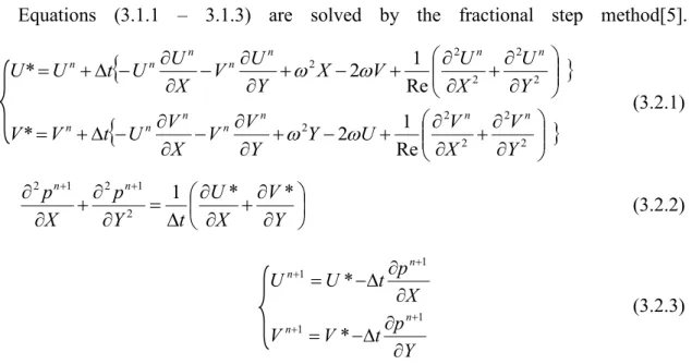
Equations (3.1.1 – 3.1.3) are solved by the fractional step method[5].
2 2 2 2 2 2 2 2 2 2 Re 1 2 * Re 1 2 * Y V X V U Y Y V V X V U t V V Y U X U V X Y U V X U U t U U n n n n n n n n n n n n n n (3.2.1) Y V X U t Y p X pn n 1 * * 2 1 2 1 2 (3.2.2) Y p t V V X p t U U n n n n 1 1 1 1 * * (3.2.3)In the advection term, the third order upstream difference shown in equation (3.2.4) is used. It is said that the upstream difference of the third order can stably solve the high Reynolds number flow even without using a turbulence model [6].
t t
t (3.2.3)
3.3 Computational domain and boundary condition
The grid shown in Fig. 12 is used for the calculation. It is fine near the wind turbine and is rough in the distance. The grid is fixed to the wind turbine, and it is rotate unsteady with the wind turbine. The boundary conditions are shown in Table 1.
Table 1. Boundary conditions.
External side of computer region On the rotor blade
Velocity Uniform flow: No-slip condition on the rotational coordinate:
Pressure Extrapolation:
Arithmetic average of pressure on the neighborhood grid points in fluid
3.4 Torque calculation and wind turbine equation of motion
Equation of Motion for Wind Turbine. The time-varying wind turbine rotation is governed by equation (3.4.1): B N t I (3.4.1) where I is the moment of inertia, N is the force that rotates the turbine (torque), and B is the force that stops the turbine, i.e., friction from the rotating shaft. Equation (3.4.1) is calculated using a Runge–Kutta method, and the wind turbine is rotated according to the obtained result.
Calculation of Torque. N is calculated from the flow field (pressure). Equation (3.4.2) calculates the torque of one grid point, and the symbols used in this equation are defined in Fig. 12. The torque of the whole turbine is obtained by calculating the sum of N for all grids.
Torque coefficient C is introduced to compare the power generation efficiency oft
different sizes of wind turbine. The torque coefficient is dimensionless torque and is expressed by equation (3.4.3):
(3.4.3) where is the density of the air, R is the radius of the turbine, H is the height of the turbine (=1.0, because two-dimensional calculations are carried out in this study), and T is the thickness of the blade.
Calculation of Force to Stop the Wind Turbine. assumes that the viscous drag works between the turbine shaft and the bearing, as shown in Fig. 13. To simplify the model, we assume that there is a gray viscous fluid between the shaft and the bearing. Close to the shaft, the viscous fluid rotates with the shaft at angular velocity . Close to the bearing, the viscous fluid does not rotate. The gradient of the rotation speed between the shaft and the bearing is . The viscous force per unit area is proportional to the gradient of the rotation speed. The viscous force per unit area generated between the turbine shaft and the bearing is , where is the viscosity coefficient. Consider the contact area between the shaft and bearing, and the
moment of force, . If all constants are combined into a
variable the equation then becomes = ; in other words is proportional to .
Fig. 12 Definition of symbols for calculation of
torque
Fig. 13 Definition of symbols for calculation of force to stop the turbine
Optimization Parameters. In this study, we investigated the characteristics of rotating wind turbines and time-varying rotation to discover the optimum wing shape. Figure 14 presents a sectional view of the Savonius wind turbine. In this study, five parameters, namely, blade length, wind turbine radius, overlap, gap, and blade thickness, were optimized.
Figure 15 shows the original wind turbine used in this study. This turbine has a blade length of 1.0 (non-dimensional length), a wind turbine radius of 1.0, an overlap of 0.0, a gap of 0.0, and a blade thickness of 0.2. The torque coefficient of the original turbine is normalized to 1.0, and this is compared with wind turbines of different shapes.
Fig. 14 Cross section of Savonius wind
turbine Fig.15 Original turbine used in this study
3.5 Steady and unsteady
In many research, wind turbine rotates at constant angular velocity. That is steady rotation. It is important to examine the basic characteristics for the design of wind turbines. ω is also an optimization parameter. For example, in Fig. 16, ω is the best rotation speed to generate the highest torque coefficient.
Fig. 16 Steady
And If the rotation speed of a wind turbine changes, that is unsteady rotation. A study on the response of wind speed. There are few examples but important. It is important to measure the characteristics under natural wind. It is necessary to decide B (friction from rotation axis) properly. As shown as Fig.17.
4. Results
This time, five parameters (blade length, wind turbine radius, overlap, gap, blade thickness) are optimized as expressed in Fig.18.
Fig. 18 Five parameters
Simulation results are shown in Fig.19-21. The vertical axis indicates the torque coefficient (power of the wind turbine). The larger the value, the better the efficiency of the wind turbine. The simulation was carried out on 33 wind turbines of different shapes.
(Blade thickness=0.1,overlap, gap=0.0)
Fig. 19. Blade length and wind turbine radius.
In Fig. 19, from (3)(5), when the radius of the turbine and the length of the blade are the same, the torque coefficient tends to be large. But small turbine like (1) can
(Radius of turbine=1.0, length of blade=1.0,overlap, gap=0.0)
(Radius of turbine=1.0, length of blade=1.0,blade thickness=0.1)
Fig. 22. Wind turbine with the highest torque coefficient.
In Fig. 19, from, when the radius of the turbine and the length of the blade are the same, the torque coefficient tends to be large. But small turbine like can not generate high torque. From Fig. 20, if the blade is thick, the torque coefficient becomes small because if the blade become heavy, the wind turbine can not rotate easily. As shown in Fig. 21, the torque coefficient becomes lower as the gap becomes larger. These trends qualitatively agree with experiment for steady rotating wind turbines[7].
Compared with other wind turbines, the torque coefficient of the wind turbine shown in Fig. 22 is the highest.
5 Conclusion and Discussion
In this study, we investigated the characteristics of rotating wind turbines and investigated the time varying rotation in order to investigate the optimum wing shape. Five parameters (blade length, wind turbine radius, overlap, gap, blade thickness)
were changed, and optimum shape was obtained. The tendency of simulation results qualitatively agreed with the experimental results for steady rotating wind turbines.
Ⅱ
. Researching for finding the influence of wind direction on two
Darrieus-type wind turbines.
1. Introduction
As latest emergency power source, small wind turbines are watched with keen interest. Since the small wind turbines are useful for the construction of distributed power generation systems, the demand of the small wind turbines will increase for some time in the future. There are two main types of the wind turbines, that are the horizontal-axis wind turbine (HAWT) and vertical-axis wind turbine (VAWT). The former is the more conventional wind turbine whose axis of rotation is parallel to the main flow. The HAWT has been the main subject of wind turbine researches for decades. The latter has attracted much more attention in recent years, whose axis of rotation is perpendicular to the main flow. The VAWT has an advantage over the HAWT in the flexibility about the direction of the main flow.
There are two major types in VAWT that are the Savonius rotor and Darrieus rotor. Since the Darrieus rotor, which generates power due to the lift force produced by rotating airfoils, has larger power coefficient than the Savonius rotor in general, we decided to focus on the Darrieus-type VAWT in the second part.The Darrieus-type VAWT as shown in Figure 1.
The wind turbine is expected to be a candidate that is source of renewable energy and solves the global environmental problems associated with CO2 emission. The small wind turbines are easily introduced as local electric energy source equipment for residences in suburb. The present experimental study focuses on a small wind turbine which has accessible possibility of renewable energy.
A straight-bladed vertical-axis wind turbine (This is called commonly Straight Darrieus Turbine) is one of the reliable wind turbines[1][2]. It is expected that
multiple small wind turbines will be installed in close proximity. Because small wind turbines can generate less electricity than large wind turbines. If they are installed in close proximity, the interaction between wind turbines cannot be ignored. In this study, two numerical simulation comparative experiments will be done to verify this
conjecture. The experiment will be set to one when the wind from left side, and the left from front side.
(a) Case1: Wind from the left side
(b) Case 2: Wind from the front side
2.Theory and numerical method of wind turbine
2.1Dynamical model of the wind turbineThe dynamic model of the wind turbine is shown in Fig. 3. The dynamic equation of the wind turbine is
a w dt d wt
Q
Q
I
(2.1.1)where Qw is the net torque [N・m], Qa is the torque generated from the wind
turbine[N・m], is the angular velocity of the rotor[rad/sec], and I is the inertialwt
moment of the wind turbine [kg・m² ]. The net torque of the rotor by the wind is calculated by
dt
d
I
Q
Q
w a wt
(2.1.2)The wind turbine was connected to the motor via the torque converter, and the torque of the rotor is measured under constant rotational speed. If the inertial term is ideally neglected, namely QwQa. However, actually
has certain variation due toFig. 3. Dynamical model of the wind turbine
2.2 Basic equations
The flow field around the wind turbine is represented by a rotating coordinate system rotating with a wind turbine. The fundamental equations are continuous equations (2.2.1), incompressible Navier Stokes equations (2.2.2) and (2.2.3). They are expressed in upper case letters. On outer grid, a stationary coordinate system expressed in lower case letters, as in the Eqs. (2.2.4)-(2.2.6). Two-dimensional calculation is carried out.
(2.2.1) Re (2.2.2) Re (2.2.3) (2.2.4) Re (2.2.5) Re (2.2.6)
where is the pressure. ( YX, ) and ( VU, ) are the position and velocity components on the rotating coordinate system and is angular velocity, respectively. There are following relations between the steady coordinate system and the rotational one:
sin cos Y X x (2.2.7) cos sin Y X y (2.2.8) sin cos y x X (2.2.9)
cos
sin y x
Y (2.2.10)
Also, relations of velocity components between two coordinate systems are as follows: y v U u cos sin (2.2.11) x V U v sin cos (2.2.12) Y v u U cos sin (2.2.13) X v u V sin cos (2.2.14) 2.3 Numerical Solution
Equations (2.2.1)-(2.2.6) are solved by the fractional step method, and the third-order upwind differencing scheme is used in the advection term as explained in section I. 3.2.
2.4 Calculation of Torque
Torque N is calculated from the flow field (pressure). The equation (2.4.1) calculates the torque of on one grid point. The symbols used in Eq. (2.4.1) are defined in Fig. 4. Torque of the whole wind turbine is obtained by calculation from sum of
N on all grids. i i i
P
r
x
N
(2.4.1)Torque coefficient Ct is introduced to compare the power generation efficiency of different sized wind turbines. The torque coefficient is dimensionless torque and is expressed by Eq(2.4.2).
H R N Ct 2 2 (2.4.2)
Where, : density of air, R: radius of turbine, H: height of turbine(=1.0. because two-dimensional calculations are done in this study)[4].
Fig. 4. Calculation of Torque on one grid point
2.5 Grid systems
The grids are generated separately in two regions each of which includes one wind turbine as shown in Fig.5. They are connected along one side CD as shown in the figure.
Each region has two sub-regions A and B. The region A rotates together with the wind turbine and the region B is fixed in the space. The outer boundary of A and inner boundary of B is "overlapped circle" so that it is easy to transfer the flow data of one region into another region through the interpolation.
In region A.O-type grid system is chosen because it is not sensitive to the flow direction that changes as the wind turbine rotates. For the accuracy of the calculation, the grids are concentrated near the blades.
above.
Fig. 5. Regions of grid system
2.6 Boundary condition
Two wind turbines are assumed to rotate with the same angular velocity. No-slip condition is imposed on the blades. On the far boundary, the flow is assumed to be uniform.
2.7 Calculation condition
We simulate the flow field around two rotating SW-VAWTs with two blades. The turbines are of the same size and shape, and rotate in same direction, at same speed
In order to estimate the performance of the wind turbine, we generally need to change tip speed ratio defined by the following formula:
V
R
(2.7.1)R: radius of wind turbine, V : wind speed
The radius of wind turbine i.e. half distance between blades is 2.8 times as long as the chord length. By setting the parameter A =2. We calculate the flow. The Reynolds number based on the uniform flow and the cord length is 2000.
3 Results and discussions
Simulation was carried out when two wind turbines are in the position of upstream and downstream against wind. Simulation result is shown in Fig. 6 (a). The vertical axis is the torque coefficient. Think of the amount of power generation. The horizontal axis is rotation angle of wind turbines during 5 turns. Blue solid line shows the time history of torque coefficient of upstream wind turbine. Orange broken line shows that of downstream wind turbine. Time average of the torque coefficient when the wind turbine rotates 3 to 4 turns is calculated. 0.906 is obtain by upstream wind turbine, 0.791 by downstream wind turbine. The average of torque coefficient of the downstream wind turbine is small, 87% compared to upstream wind turbine.
A similar simulation was carried out with the wind direction changed. Wind turbines are in the position of parallel to wind. 0.900 is obtain by a wind turbine which is on the right when viewed from the upstream side, 0.877 by another wind turbine. The torque coefficient is approximately the same.
(a) case 1 Wind from the front side
(b)case 2 Wind from the right side Fig. 6. Time history of the torque coefficient
4 Conclusion
For two Darius-type wind turbines, the torque coefficient generated under some different wind direction was examined by simulation. The average of torque coefficient of the downstream wind turbine became small (87% compared to upstream wind turbine).
Small wind turbines are often installed close to each other. I will study in detail how far away the downstream side wind turbine can generate enough torque.
References
I. Research on the best shape of Savonius wind turbine.
[1] Evans, Annette & Strezov, Vladimir & Evans, Tim J., 2009. "Assessment of sustainability indicators for renewable energy technologies," Renewable and Sustainable Energy Reviews, Elsevier, vol. 13(5), pages 1082-1088, June.
[2] A.R.El-Bazac, K.Youssef, M.H.Mohamed, "Innovative improvement of a drag wind turbine performance", Renewable Energy, 86, pp. 89-98, (2016).
[3] Coherent application threads (http://people.bu.edu/dew11/windasenergy.html) last access date; Feb. 17th, 2020
[4] Coherent application threads (http://people.bu.edu/dew11/liftanddrag.html ) last access date; Feb. 17th, 2020
[5] N.N. Yanenko, "The method of fractional steps", Springer-Velag, (1971).
[6] T.Kawamura and K. Kuwahara, "Computation of high Reynolds number flow around a circular cylinder with surface roughness", AIAA Paper, 84-0340, 1984. [7] I. Ushiyama, H Nanagi and J Shinoda, "Experimentally Determining the Optimum
Design Configuration for Savonius Rotors", Bulletin of JSME, 29(258), pp.4130-4138, (1986).
[8] T.Kawamura and K. Kuwahara, "Computation of high Reynolds number flow around a circular cylinder with surface roughness", AIAA Paper, 84-0340, 1984. [9] I. Ushiyama, H Nanagi and J Shinoda, "Experimentally Determining the Optimum
Design Configuration for Savonius Rotors", Bulletin of JSME, 29(258), pp.4130-4138, (1986).
Ⅱ.Researching for finding the influence of wind direction on
two Darrieus-type wind turbines.
[1] Mizuno, A., The Scale Effect of Straight-Wing Vertical-Axis Wind Turbines, Proceedings of the 24th Symposium on Wind Energy (2002), pp.195-197 (in Japanese)
[2] Ushiyama, I., Introduction of the Wind Turbine Engineering (2002), p.55, Morikita publishing (in Japanese).
[3] Yamada, S., Tamura, T. and Mochizuki, S., Effects of Wing Section on Mean Characteristics and Temporal Torque Variation for Small Straight-Bladed Vertical Axis Wind Turbine, Journal of Fluid Science and Technology, Vol.6, No.6 (2011), pp.875-886.
[4] Anna Kuwana. Analysis of Interaction Between Multiple Rotating Devices
by CFD(2019) Proceedings of International Conference on Mechanical, Electrical and Medical Intelligent System. 2019
Research Achievements
[1] Haruo Kobayashi, Yuto Sasaki, Hirotaka Arai, Dan Yao, Yujie Zhao, Xueyan Bai, Anna Kuwana, “Unified Methodology of Analog/Mixed-Signal IC Design Based on Number Theory”, IEEE 14th International Conference on Solid-State and Integrated Circuit Technology, Qingdao, China (Nov. 2018) (IEEE Xplore)
[2] Bai Xueyan, Anna Kuwana, Haruo Kobayashi, “Numerical Simulation for Optimization of Unsteady Rotating Wind Turbine”,5th International Symposium of Gunma University Medical Innovation and 9th International Conference on
Advanced Micro-Device Engineering, kiryushi, Japan (Dec.2018) (GUMI&AMDE2018)
[3] Bai Xueyan, Anna Kuwana, Haruo Kobayashi, Yao Dan, “Numerical
Simulation for Optimization of Unsteady Rotating Wind Turbine”, 第9回群馬・栃
木支所合同研究発表会,栃木県小山市,日本(Mar. 2019)
[4] Bai Xueyan, Anna Kuwana, Haruo Kobayashi, Yao Dan, “Numerical Simulation for Optimization of Unsteady Rotating Wind Turbine”, International Conference on Technology and Social Science 2019, kiryushi, Japan (May, 2019)(ICTSS 2019)
![Fig. 3. Power Available from the wind[3]](https://thumb-ap.123doks.com/thumbv2/123deta/6324658.1097785/8.892.193.694.593.977/fig-power-available-from-the-wind.webp)
![Fig. 4. Wind Speed, Power and Height(300m² capture area)[3]](https://thumb-ap.123doks.com/thumbv2/123deta/6324658.1097785/9.892.180.679.103.541/fig-wind-speed-power-height-m-capture-area.webp)