JAIST Repository: An HTIP L2 agent solution for network equipment using openflow
7
0
0
全文
(2) Vol.2018-MBL-86 No.14 Vol.2018-UBI-57 No.14 2018/2/26. IPSJ SIG Technical Report. An HTIP L2 Agent Solution For Network Equipment Using OpenFlow Sioutis Marios1,a). Lim Yuto1,b). Tan Yasuo1,c). Abstract: In order to provide customers with effective remote support for the rising number of appliances in the home, network topology information is necessary. The Home-network Topology Identification Protocol (HTIP) is a protocol which can provide the information needed to deduce the home network topology. In this paper we present an open source HTIP L2 agent implementation based on Ryu, a popular OpenFlow SDN framework. This solution can aid the testing and development of HTIP managers and agents, reducing costs and improving interoperability. The correct HTIP behaviour as well as the performance characteristics of this L2 agent are demonstrated through experiments and areas for future improvement are discussed. Keywords: HTIP, Home Network, Network Topology, Software-Defined Network, OpenFlow. 1. Introduction With advances in IoT technology, the number of networkenabled devices connected to the home network is constantly rising. As the number of such devices increases, their management and their trouble-free operation becomes a daunting task for the average user, who is rarely equipped with the necessary technical knowledge to troubleshoot any problems that may come up. To support users in the task of managing devices and the home network in an effective way, a strong case can be made for remote technical support systems. It is possible to provide technical support and troubleshooting of home devices remotely, assuming that technical information regarding device operation can be shared with the remote assisting party in a consistent and standardized fashion. Currently, the Broadband Forum proposes the TR–069 CPE WAN Management Protocol[1] as a solution for device management. Furthermore, customer support guidelines are discussed in TCC TR-1057[2] and customer support use cases are discussed in TTC TR-1062[3]. One of the most critical pieces of information necessary for remote troubleshooting is network topology information. To this extent, the Home–network Topology Identification Protocol (HTIP) [4] has been proposed as a solution to the problem of gathering relevant network topology information in the context of a home network. However, since HTIP is relatively new, the number of commercially available devices that support it is low. To help further the growth and adoption of HTIP as the de– facto method of collecting network topology information in the home, in this paper we introduce an open–source implementation 1. a) b) c). Japan Advanced Institute of Science and Technology, Nomi, Ishikawa 923–1201, Japan [email protected] [email protected] [email protected]. c 2018 Information Processing Society of Japan ⃝. of the HTIP L2 agent for NW equipment*1 . This L2 agent provides link information for each port of the NW equipment based on information from the MAC forwarding table of this device. It is expected that future switching hubs will integrate HTIP L2 agent functionality, but as of right now no such switches are yet commercially available. Our HTIP L2 agent implementation fills this gap by providing an L2 agent which can be deployed on general purpose computers that have multiple network interfaces. Authors of HTIP manager software can use this L2 agent implementation for testing and interoperability checks, thus speeding up development and guaranteeing conformance. Furthermore, this L2 agent can be deployed on virtual machines and be used as part of large scale home simulations that test manager software scalability and performance. The L2 agent implementation uses the Software Defined Networking technology OpenFlow[5].The use of OpenFlow enables complete control over the behaviour of the switch by allowing control over how each individual incoming packet is handled. It is thus possible to generate and maintain a MAC address forwarding table which will be used as the basis for generating appropriate HTIP information. Furthermore, the L2 agent consists of two parts: an OpenFlow controller and an OpenFlow switch. The controller is implemented as a Python application running on top of the Ryu SDN Framework[6]. The controller has so far been tested with the Open vSwitch[7] OpenFlow switch for the Linux operating system. The OpenFlow controller which was developed is distributed as open source software under the BSD 2-clause license, available from ⟨https://github.com/s-marios/dragontip⟩. In the following sections we discus topics such as the core concepts of HTIP and OpenFlow, application design and implemen*1. A representative example of NW equipment is an Ethernet switching hub that utilizes a MAC forwarding table.. 1.
(3) Vol.2018-MBL-86 No.14 Vol.2018-UBI-57 No.14 2018/2/26. IPSJ SIG Technical Report. tation details, evaluation of the L2 agent in terms of correctness and performance as well as concluding remarks and future works, in that order.. 2. Core Technologies The two core technologies involved in this research are the HTIP protocol and the OpenFlow SDN protocol. A brief introduction for these two technologies follows. 2.1 HTIP HTIP is designed to solve the problem of gathering home network topology information. To achieve this goal, it is imperative that HTIP functionality can be easily integrated into home devices, from resource-constrained embedded devices to more powerful devices running general-purpose operating systems. As such, HTIP builds upon two well-proven technologies, the Link Layer Discovery Protocol (LLDP)[8] and Universal Plug-n-Play (UPnP)[9]. These technologies are used as a base on which the functionality of the various HTIP entities is defined. There are 3 major entities in HTIP: • HTIP manager, • HTIP L2 agent, • HTIP L3 agent. The scope and functionality of HTIP managers can vary. Although the exact behaviour of an HTIP manager is not defined in the specification, HTIP managers are generally expected to utilize information produced by L2/L3 agents and provide support functionality such as automated error reports, network and device status, network topology information etc. For example, it is the responsibility of an HTIP manager to extract an accurate overall network topology from the HTIP information it has gathered so far. An L2 agent is software that is expected to be deployed on a device, providing generic information such as device category, model number and other optional information such as link quality, CPU usage rate, periodic transmission interval and others. Furthermore, L2 agents can be deployed on network equipment such as switches and routers. In this case, an L2 agent must also provide link information for each network port present on the network equipment. L2 agents transmit this information periodically in the form of LLDP Data Units (LLDPDUs). However, contrary to LLDP where the destination address is a multicast MAC address, HTIP chooses to use the broadcast MAC address FF:FF:FF:FF:FF:FF. An LLDPDU is a collection of TypeLength-Values (TLVs) that are used to express the type, length and value of a specific piece of information. The specific binary format of the TLVs that encode HTIP information (namely the “value” part of the TLV) can be found in the HTIP specification. The L2 agents are not expected to receive any HTIP information (with the exception of implementing an optional feature which allows the control of HTIP retransmission information). This fact combined with the simplicity of the TLVs and the use of broadcast MAC address as the destination make the development of simple L2 agents relatively easy, even on embedded systems. On the other hand, network equipment with L2 agent func-. c 2018 Information Processing Society of Japan ⃝. tionality (including link information) has yet to be commercially released. L3 agents are the last major entity in the HTIP ecosystem. L3 agents operate using UPnP and are intended to be deployed on home devices. L3 agents report the same kind of information as L2 agents, except the link information reported by L2 agents on network equipment. Adding L3 agent functionality to a device that already supports UPnP should be relatively straightforward; depending on the information that is reported as well as the underlying UPnP library, L3 agent functionality may be achieved by adding the required XML elements to the device description. The biggest difference between L3 agents and L2 agents is that HTIP managers can query an L3 agent for information at any given time, thus ensuring that its host is operational at that point in time. As a closing note on HTIP, it must be said that HTIP can also support communication media other than those of the Ethernet family through specific extensions that are optional, making HTIP a future-proof proposition. 2.2 OpenFlow OpenFlow is among the most well known SDN technologies. With the use of OpenFlow a clear distinction between the data plane and control plane of network equipment such as switches and routes can be achieved. In other words, the logic of handling incoming traffic is relegated to a controller, which is in turn able to generate forwarding rules for the controlled switch called flows. The actual processing of incoming traffic happens at the switch, and any traffic that cannot be matched to any established flow is sent to the controller. The controller can then decide the fate of the incoming traffic by taking actions such as forwarding the packet to specific/all ports of the switch, drop the traffic, modify protocol fields and optionally establish flows for the underlying switch. OpenFlow provides great flexibility when it comes to handling of incoming traffic. Many implementations of network protocols such as routing protocols already exist based on OpenFlow*2 . Furthermore, an application developed using an OpenFlow framework can focus only on a subset of traffic matching specific criteria and perform specialized actions, while at the same time process the rest of the traffic transparently, just like a normal switch would. These characteristics make OpenFlow an ideal platform on which a variety of specialized network applications can be build, including our HTIP L2 agent implementation for network equipment.. 3. Design and Implementation Details 3.1 Software and Hardware Details The HTIP L2 agent for network equipment is split into two parts: the OpenFlow controller and the OpenFlow switch. The controller is implemented as a Python application running on top of the Ryu SDN Framework, version 4.15. Currently, it utilizes Python variable annotations so it is restricted to versions of Python 3.6 and above. Open vSwitch is used as the OpenFlow *2. For example, the Ryu SDN Framework provides library support for the BGP routing protocol.. 2.
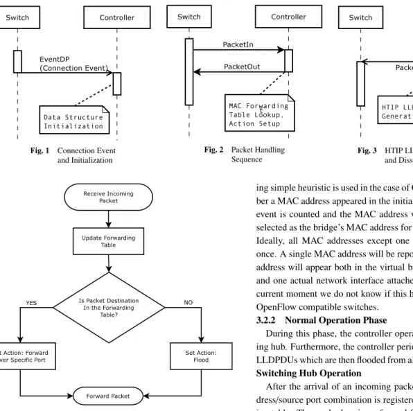
(4) Vol.2018-MBL-86 No.14 Vol.2018-UBI-57 No.14 2018/2/26. IPSJ SIG Technical Report. Fig. 1. Connection Event and Initialization. Fig. 4. Fig. 2. Packet Handling Sequence. Simple Switching Hub Logic. switch of choice, running on Linux kernel version 4.9. Both the controller and the switch utilize OpenFlow protocol version 1.0. The hardware used for the switch is an Intel NUC 6th generation with external USB Ethernet adapters. 3.2 Controller Design The OpenFlow controller application goes through two distinct phases during its lifecycle: an initialization phase and then a normal operation phase. 3.2.1 Initialization Phase During the initialization phase the controller waits for a connection request from a managed OpenFlow switch. As soon as a switch connects*3 , the controller receives an “EventDP” event. This event contains information regarding the ports present on the switch, such as their MAC addresses, port number, state, configuration, capabilities etc. This initialization sequence can be seen as a sequence diagram in Fig. 1. Using this information, the controller initializes its basic data structures such as the MAC forwarding table, initializes the list of network interface ports, and finally selects the main MAC address of the bridge. To select this “main” MAC address for the switch, the follow*3. or for that matter, disconnects. c 2018 Information Processing Society of Japan ⃝. Fig. 3. HTIP LLDPDU Generation and Dissemination. ing simple heuristic is used in the case of Open vSwitch: the number a MAC address appeared in the initial “EventDP” connection event is counted and the MAC address with the higher count is selected as the bridge’s MAC address for future communications. Ideally, all MAC addresses except one should be reported just once. A single MAC address will be reported twice, as this MAC address will appear both in the virtual bridge port of the switch and one actual network interface attached to the switch. At the current moment we do not know if this heuristic applies to other OpenFlow compatible switches. 3.2.2 Normal Operation Phase During this phase, the controller operates as a simple switching hub. Furthermore, the controller periodically generates HTIP LLDPDUs which are then flooded from all the ports of the switch. Switching Hub Operation After the arrival of an incoming packet, the source MAC address/source port combination is registered in the MAC forwarding table. Then, a lookup is performed for the destination MAC address of the incoming packet in the MAC forwarding table. If there is an entry (i.e. this destination MAC address is already associated with a port on the switch) an action for forwarding the packet through that specific port is generated. If the lookup fails, an action for flooding the packet through all the ports of the switch is generated instead. Finally, the switch is instructed to forward the incoming packet according to the action that was generated after the table lookup. The switching hub operation logic can be seen in Fig. 4. The overall packet handling sequence involving the switch and the controller can be seen as a sequence diagram in Fig. 2. In the current implementation, no flows are generated; each incoming packet will inevitably be sent to the controller for evaluation. HTIP Operation A different thread periodically generates HTIP LLDPDUs which are then forwarded to the switch to be sent through the network using a flood action. This thread generates the appropriate TLVs, starting first from the required LLDP TLVs such as chassis id, port id, Time-to-Live. Then, HTIP TLVs of subtype 1 are added, such as device type, maker code, model name and model number. Continuing, the thread generates the HTIP subtype 2 TLV i.e. the TLV which contains information from the MAC address forwarding table. The MAC address forwarding ta-. 3.
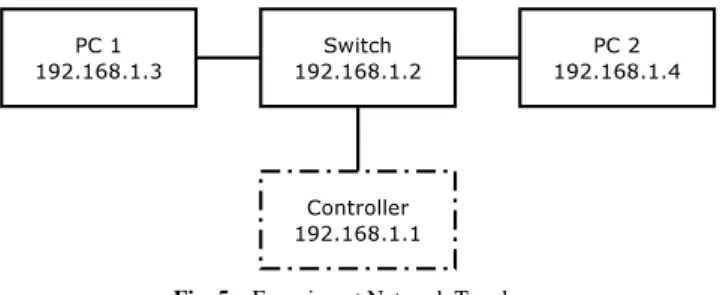
(5) Vol.2018-MBL-86 No.14 Vol.2018-UBI-57 No.14 2018/2/26. IPSJ SIG Technical Report. Fig. 5. Experiment Network Topology. ble maintains mappings in the form of MAC address → Port, but this TLV requires the reverse mapping (i.e Port → List of MAC addresses). Finally, the HTIP Subtype 3 TLV is added. This TLV contains all the known MAC addresses used by the switch. After the HTIP LLDPDU has been created, it is sent to the switch using a PacketOUT request. This sequence can be seen as a sequence diagram in Fig. 3.. 4. Evaluation In this section we discuss the experiments conducted for the evaluation of the HTIP L2 agent implementation for network equipment. After the setup used for the experiments is explained, we proceed to discuss the two types of experiments conducted: HTIP behavioural conformance tests and actual packet forwarding performance tests. For each of these experiments, a discussion about the results obtained as well as commentary regarding any identified limitations is provided. 4.1 Experiment Setup The network topology used for the experiments of this section can be seen in Fig. 5. For all of the experiments, a switch as well as two generic PCs (named PC 1 and PC 2) were present. These hosts are denoted with a solid line. In some experiments an external controller was also present, denoted with a dash-and-dot line. The solid lines connecting these hosts represent 1000baseT (i.e. 1Gbps) full-duplex Ethernet connections. MAC addresses have been omitted for the sake of brevity. The three interfaces present on the switch are combined to a single bridge interface and they are assigned a single IP address. The hardware and software details regarding the switch were discussed in Sec. 3.1. PC 1 is a MacBook Air 2012 model, PC 2 has the same specifications as the switch (Intel NUC 6th generation, Intel Core i3-6100u 2 core / 4 thread CPU, 8GB of RAM) and the external controller is a desktop computer with AMD Ryzen 1950X processor and 32GB of RAM. Other hardware details are omitted as they are not relevant to the experiments. The PC1, PC2 and controller hosts have sufficient hardware specifications as not to become performance bottlenecks. Thus, any observations regarding performance focus mostly on the switch and possibly on the communication overhead with the external controller. 4.2 Correctness of HTIP Operation To verify the correct HTIP operation of the switch, the forwarding table as reported by the controller as well as the captured HTIP LLDPDU on PC 1 are used. In this scenario, PC 1 initiates. c 2018 Information Processing Society of Japan ⃝. new mac: 00:23:20:a7:9a:df #NiciraNe new mac: 00:22:cf:f9:62:f6 #PC 1 new mac: 00:22:cf:f9:63:3c #Controller new mac: 00:22:cf:f9:63:3f #Switch new mac: 00:22:cf:f9:62:c6 #PC 2 --{65534: {’00:22:cf:f9:63:3f’, ’00:23:20:a7:9a:df’}, 2: {’00:22:cf:f9:62:f6’}, 1: {’00:22:cf:f9:63:3c’}, 3: {’00:22:cf:f9:62:c6’}} Fig. 6. Controller Output and Port-to-MAC Address Mappings. ping requests to the controller, switch and PC 2 in that order. In the shortened output from the controller seen in Fig. 6, the MAC addresses of PC 1, controller and PC 2 appear for the first time. Special mention must be made to the bridge port (interface br0, port number 65534) which manages to learn one of the MAC addresses used by the switch itself as well as an unaccounted MAC address that does not belong to any physical network interface. First, the bridge interface “learns” the MAC address of the underlying network interface as a result of a ping request from PC 1 to the switch itself. This sheds some light regarding the internal processing of packets in the bridge. Secondly, regarding the unaccounted MAC address, upon closer inspection, the vendor of this MAC address is NiciraNe Nicira Networks, the company associated with the development of OpenFlow and its specifications. A single reverse ARP packet originated from this MAC address and it is considered to be part of the OpenFlow switch initialization. Next, by performing a network capture on PC 1 at the same time, the resulting HTIP LLDPDU was verified to contain the correct HTIP and port link information. First, the LLDPDU contained the TLVs for chassis subtype, port subtype and time-tolive. Then, four HTIP TLVs with subtype 1 were present. After that, the HTIP subtype 2 TLV was present and its contents can be seen below (formatted in lines for clarity) : 010602 fffe020022cff9633f002320a79adf 0001010022cff9633c 0002010022cff962f6 0003010022cff962c6 Each line excluding the first contains the port number as a two byte integer, the number of MAC addresses associated with that port and finally the list of addresses itself. Except from a slight reordering, the information matches that reported by the controller itself. Continuing, HTIP subtype 3 TLV was present, containing the 3 MAC addresses associated with the switch. The End TLV finishes out the captured packet. From this experiment we conclude that the switch is able to generate HTIP LLDPDUs with well-formed TLVs and that the contents of the MAC forwarding table are properly reflected in them. A discussion is necessary regarding the detection of hosts leaving the network. In its current implementation, the L2 agent will update the port a host is plugged into if it changes. However, it cannot detect if a host has become inactive. There are two possible countermeasures that will be considered as future work: 4.
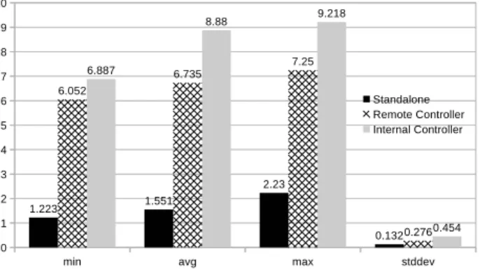
(6) Vol.2018-MBL-86 No.14 Vol.2018-UBI-57 No.14 2018/2/26. IPSJ SIG Technical Report. Fig. 7. ping Results: Round-Trip Time (in ms). • Port Link Down events. An event of this type signifies that whatever device was connected to that port is no longer there. This is enough information to remove all the MAC addresses that have so far been associated with that port as they have now become unreachable. Some limitations still exists, such as the scenario of a chained switching hub being present at that port; a link down event will never occur, thus we are unable to discern whether any host associated with that port is reachable or not. • Timeout mechanisms. Timeout mechanisms based on ICMP Echo requests, ARP requests and others may be useful when it comes to deciding if a host is reachable or not. These techniques may however return false positives (i.e. a host declared as unreachable when in fact it is still reachable) depending on the security settings and/or capabilities of these hosts. 4.3 Switch Performance Considerations In this section, a rudimentary exploration of the performance that the L2 agent can offer as a whole (switch & controller) is made. The basic metrics used here are throughput and round-trip times of packets traveling through the switch. For this purpose the popular iperf3 and ping tools were used. Traffic was generated from PC 1 towards PC 2. To establish a performance baseline, in the first scenario the switch operated autonomously i.e. without communicating with a controller. In this mode, Open vSwitch operates as a standalone switching hub, without any HTIP capabilities, In the second scenario, the OpenFlow controller application was deployed remotely, on the host denoted with a dash-and-dot line in Fig. 5. Finally, in the third scenario, the controller application was deployed directly on the switch, without the need for an external controller. The round-trip time as reported by the ping command can be seen in Fig. 7. When the switch operates in standalone mode, the round-trip time between PC 1 and PC 2 is on average 1.5ms. For the remotely deployed controller and the internally deployed controller cases, the average round-trip times are 6.7ms and 7.3ms respectively. The introduction of the HTIP controller increases the roundtrip time roughly 4 to 5.5 times, compared to standalone operation. The situation is even more dramatic when we consider the throughput results as reported by iperf3, seen in Fig. 8. Compared to the standalone operation of Open vSwitch in. c 2018 Information Processing Society of Japan ⃝. Fig. 8. iperf3 Results: Throughput (in Mbits/s). which it is able to saturate the 1Gbit interfaces attached to the switch, the introduction of the HTIP OpenFlow controller causes a 20-fold decrease in throughput if deployed remotely, and a 22-fold decrease in throughput when deployed internally on the switch itself. This drop in performance can be explained by the fact that the current implementation does not utilize flows. In other words, every single incoming packet is passed to the controller, the controller decides on a forwarding action that must be taken and the packet is then passed back to the switch for forwarding, resulting in higher overall packet processing time. The use of flows is planned for a future revision of the HTIP L2 agent. With the use of flows, it is expected that throughput will resemble much more closely the throughput exhibited by Open vSwitch in standalone mode. The final but still very interesting performance observation is the fact that the controller performs better when deployed remotely rather than locally. Although the performance in both cases is comparable, and for all intents and purposes enough for most of the daily needs in a home environment, it is still interesting to see that the deployment which utilizes the network outperforms a solution which does not utilize it, and contains the packet processing inside the same networking stack. This could possibly be attributed to the use of the Ryu SDN framework which is written in Python; other SDN frameworks may perform better. Still, it is worth keeping in mind that the current implementation is unusual since it requires all incoming packets to pass through the controller before being forwarded, instead of utilizing flows.. 5. Conclusions and Future Work In this paper the implementation of an HTIP L2 agent for network equipment was introduced. This agent is developed using the Ryu SDN framework which implements the OpenFlow protocol and it can be deployed in any general purpose computer. This agent fills an important gap in the HTIP ecosystem, since there are no such commercially available solutions yet. The L2 agent was demonstrated to generate proper link information based on its internal MAC address forward table, and it can thus be used for testing and interoperability purposes when designing and developing HTIP manager applications. Furthermore, its performance was explored in terms of round-trip time and achievable throughput. The current implementation can achieve adequate throughput for deployment in home environments. Since this is a software-only solution, it can be easily deployed on virtual ma5.
(7) IPSJ SIG Technical Report. Vol.2018-MBL-86 No.14 Vol.2018-UBI-57 No.14 2018/2/26. chines and used in large-scale home and community simulations. This implementation is open source software, provided under the BSD 2-clause license available from ⟨https://github.com/smarios/dragontip⟩. As future work, two areas have been identified for immediate improvements. First, the performance of the HTIP L2 agent can potentially improve greatly through the utilization of flows. If flow utilization is implemented, performance levels may reach the levels of standalone operation, i.e. close to saturating the network interface speed. The second area that should be addressed is the detection of hosts that were either disconnected from the network or are otherwise non-operational. For hosts that are directly connected on to the switch, the detection of port link down events provides immediate information about the status of the connected host at that port. OpenFlow does report such events, and their integration in the current implementation should be trivial. A polling approach based on ICMP echo requests, ARP requests and others can be also pursued. Finally, future functionality that can be pursued is the introduction of HTIP manager functionality, such as the ability to produce overall network topology information by aggregating HTIP L2 and L3 agent information from other hosts in the network. References [1]. [2]. [3]. [4]. [5]. [6] [7] [8]. [9]. The Broadband Forum: TR-069 CPE WAN Management Protocol, (online), available from ⟨https://www.broadbandforum.org/technical/download/TR-069 Amendment-5.pdf⟩, (accessed 2018-01-20). Telecommunications Technology Committee: Customer support guideline for home network service, (online), available from ⟨https://www.ttc.or.jp/jp/document list/pdf/e/TR/TR1057(E)v1.1.pdf⟩, (accessed 2018-01-20). Telecommunications Technology Committee: Customer support use cases for home network services, (online) available from ⟨https://www.ttc.or.jp/jp/document list/pdf/e/TR/TR1062(E)v1.1.pdf⟩, (accessed 2018-01-20). Telecommunications Technology Committee: Homenetwork Topology Identification Protocol, (online), available from ⟨https://www.ttc.or.jp/jp/document list/pdf/e/STD/JJ300.00(E)v3.pdf⟩, (accessed 2018-01-20). Open Networking Foundation: OpenFlow Switch Specification, (online), available from ⟨https://www.opennetworking.org/wpcontent/uploads/2014/10/openflow-switch-v1.5.1.pdf⟩, (accessed 2018-01-22) Ryu SDN Framework Community: Ryu SDN Framework, available from ⟨https://osrg.github.io/ryu/⟩ (accessed 2018-01-22) The Linux Foundation: Open vSwitch Documentation, (online) available from ⟨http://docs.openvswitch.org/en/latest/⟩ (accessed 2018-0122) IEEE Computer Society: 802.1AB-2009 - IEEE Standard for Local and Metropolitan Area Networks– Station and Media Access Control Connectivity Discovery, (online) available from ⟨http://ieeexplore.ieee.org/document/5251812/⟩ (accessed 2018-0122) UPnP Forum: UPnP Device Architecture 1.0, (online) available from ⟨http://www.upnp.org/specs/arch/UPnP-arch-DeviceArchitecturev1.0-20080424.pdf⟩ (accessed 2018-01-22). c 2018 Information Processing Society of Japan ⃝. 6.
(8)
図
関連したドキュメント
In this case, the extension from a local solution u to a solution in an arbitrary interval [0, T ] is carried out by keeping control of the norm ku(T )k sN with the use of
Keywords: continuous time random walk, Brownian motion, collision time, skew Young tableaux, tandem queue.. AMS 2000 Subject Classification: Primary:
Thus, we use the results both to prove existence and uniqueness of exponentially asymptotically stable periodic orbits and to determine a part of their basin of attraction.. Let
In this paper, we propose an exact algorithm based on dichotomic search to solve the two-dimensional strip packing problem with guillotine cut2. In Section 2 we present some
The linearized parabolic problem is treated using maximal regular- ity in analytic semigroup theory, higher order elliptic a priori estimates and simultaneous continuity in
Applications of msets in Logic Programming languages is found to over- come “computational inefficiency” inherent in otherwise situation, especially in solving a sweep of
Shi, “The essential norm of a composition operator on the Bloch space in polydiscs,” Chinese Journal of Contemporary Mathematics, vol. Chen, “Weighted composition operators from Fp,
A Darboux type problem for a model hyperbolic equation of the third order with multiple characteristics is considered in the case of two independent variables.. In the class
