九州大学学術情報リポジトリ
Kyushu University Institutional Repository
都市部電力供給用23 kV三相同軸HTSケーブルを用い たHTSプラットフォームの設計と経済的評価に関する 研究
李, 哲休
https://doi.org/10.15017/4060194
出版情報:Kyushu University, 2019, 博士(工学), 課程博士 バージョン:
権利関係:
A Study on the Design and Economic Evaluation of HTS Power Platform with
23 kV Tri-axial HTS Power Cables for Urban Power Supply
March 2020
Department of Electrical and Electronic Engineering, Graduate School and Faculty of Information Science and
Electrical Engineering, Kyushu University
Lee, Chulhyu
1
論文概要
現在、世界中で超伝導ケーブルの実用化に向けた研究開発が活発に進めら れている。既存のさまざまな電圧階級の送配電系統と連系するために、仕様 が異なる超電導ケーブルの試験も行われた。韓国電力では、このような開発 状況を鑑み、高温超電導ケーブルの実用化を目指して、1 km以上離れた二ヶ 所の154 kV変電所を23 kV HTSケーブルで連系するShingalプロジェクトを実 施し、この高評価を受け、世界初の商業運転に展開した。
超電導ケーブルの長所は高電流密度送電であり、同サイズの配電用フィー ダーより約5~10倍以上の電力を送電することができる。これにより、都心の 変電所建設を省略したり、変電所の都市外郭への移転のみならず、技術的制 約で解決が困難だった様々な状況を克服できるようになる。しかし、既存の 三相一括型超電導ケーブルはその高い価格により、広範囲の導入と新規投資 が難しいという欠点があった。三相同軸型ケーブルはこの課題を解決し、さ らに超電導シールドを必要とせず、さらなる価格低減を可能とし、ドイツの Ampacityプロジェクトなどでその性能が立証された。しかしながら、冷却シ ステムの制約により、1km以上の系統に導入できないという限界を露呈した。
本研究では、この課題を解決するために、三相同軸ケーブル内に冷却パス を二つ設け、ケーブル外部循環経路を別途に確保する方式を提唱、採用し た。また、都心の電力供給のための新しい電力系統構成として、23kVの超電 導同軸ケーブルを活用したHTSパワープラットフォームを提案し、伝統的な 方式との経済効果を検討した。ここでHTSパワープラットフォームとは、負 荷密度が高く、かつ、地価が高い都心に154kV変電所を建設する代わりに、敷 地面積が非常に小さい23kV開閉所を2~3ヶ所建設し、23kV HTSケーブルで 都市外郭に配置した変電所と環状網で連携して安定的に電力を供給する方式 を指す。ここでは、N-1信頼度基準を考慮しながらも、23kV開閉所の電力供給 能力と、これを連系する23kV超電導ケーブルの回線数および送電容量の間に 経済的観点で適切な調和が求められる。特に、投資代案間の比較検討におい
て、超電導ケーブルの経済性だけでなく、現場の建設環境も反映されなけれ ばならない。建設環境には、地中建設方式、ステーション用敷地価格、送電 線の経過地の制約など、経済性評価に影響を及ぼしうるさまざまな要因が含 まれる。これらを鑑みて、HTSパワープラットフォームの経済効果につい て、従来の伝統的方式と比較検討した。
本論文は、23kV超電導ケーブルを活用したHTSパワープラットフォームの デザインおよび経済性評価に関する一連の研究をまとめたもので六章で構成 される。第一章は序論で、研究背景、国内外の超電導ケーブルの開発状況お よび研究目的について記述している。第二章では、各種超電導ケーブルの比 較とともに、液体窒素の外部循環経路を備えた三相同軸型超電導ケーブルの 構成について説明している。第三章では、都心の電力供給のための新しい概 念のHTSパワープラットフォームを提案し、経済性評価のために超電導ケー ブルと冷却システムの価格算出手順を記述した。第四章では、最大360MVA 負荷供給容量を持つHTSパワープラットフォームの経済性について、多様な 設備計画シナリオ別に比較評価した。特に、超電導ケーブルの容量別の総投 資費の比較を通じて、HTSパワープラットフォームと最も適切に符合する超 電導ケーブルの容量を定量的に検討した。第五章では、実際に電力系統に適 用するための60MVA容量のHTSパワープラットフォームモデル事業の候補地 の選定およびシステムの構成について記述した。第六章は総括で、今後の課 題に対する意見も記した。
3
ABSTRACT
Research on the development of superconducting power cables for commercialization is underway worldwide. Many demonstrations of superconducting power cables connected to real power grids have been conducted with various designs depending on the voltage levels of the distribution and transmission lines. In Korea, the Korea Electric Power Corporation (KEPCO) has fully funded the Shingal Project, the first commercial project of high temperature superconducting (HTS) power cables to connect two substations with a 23 kV HTS cable over a distance of 1 km, and it has started operations successfully.
The advantage of superconducting cables, which have been rapidly developed in recent years, is their capability to transmit 5-10 times more capacity than those of feeders of the same size, making them an excellent means of avoiding building new substations and replacing transmission cables.
Given these advantages, studies on how to utilize superconducting cables are required in high load density urban areas where installing new substations and transmission cables is hindered by mounting public opposition.
The author conducted a study to supply power to urban areas using 23 kV HTS cables and proposed a new power system model called the HTS power platform to prove the method’s feasibility. This platform refers to the new configuration of an electric power grid composed of two to three 23 kV switching stations connected with each other by the 23 kV HTS cables in urban areas with high load densities and land costs. The size of the 23 kV switching stations is only 20%-30% of that of the conventional 154 kV substations.
However, the disadvantage of the conventional HTS cable (three phases in one cryostat; triad type) is that it is not easy to utilize further owing to its high investment cost. As an alternative, the development of tri-axial HTS cables without using HTS shield wires, such as those used in the AMPACITY project in Germany, enables cost reductions, but a limitation of the cooling system keeps the HTS cables from exceeding a length of 1 km. Thus,
technical improvements in tri-axial HTS cables are needed to configure the HTS power platform.
This study verifies that the cable distance can be increased to 3 km by improving the cooling configuration of tri-axial HTS cables from the conventional internal circulation to an external circulation channel for liquid nitrogen(LN2). Consequently, the urban power supply area of the HTS power platform can be expanded with considerable flexibility. In addition, the economic impacts of construction environments, such as land costs, underground structures, and HTS cables were verified by modeling them as mathematical factors. Furthermore, the optimal circuit number and capacity ratings of HTS cables are presented through the design algorithm development of the 23 kV HTS cable system, which is a key facility for the HTS power platform. This enabled a detailed verification for the installation of an HTS power platform in a real grid in consideration of the N-1 reliability criteria and resulted in an increased feasibility of the 23 kV tri-axial HTS cables.
This doctoral dissertation is among a series of studies developing new configurations for an HTS power platform using 23 kV HTS power cables, and it consists of six chapters. Chapter 1 presents the background, purpose, and outline of this paper. Chapter 2 describes the configuration of the 23 kV tri-axial HTS cable system with an external return path for LN2. Chapter 3 introduces the new design of the HTS power platform for urban power supply.
Furthermore, it explains the estimation process for the prices of tri-axial HTS cables and a cooling system. Chapter 4 describes the economic evaluation of the HTS power platform with a load supply capacity of up to 300 MVA in consideration of its construction environments, life cycle cost and benefit, and closed-loop or radial type configuration. In particular, a comparison of the total investment cost of the HTS power platforms is described to present an appropriate HTS cable rating selection that corresponds well to the HTS power platform. Chapter 5 describes the demonstration of the 23 kV 60 MVA closed-loop HTS power platform in an actual power grid. Finally, chapter 6 summarizes the results and discusses future issues.
5
CONTENTS
CHAPTERS
ABSTRACT
1 INTRODUCTION ... 1 1.1 Electric power grid for an urban power supply 1
1.1.1 Rapid load growth and high load density in urban areas 1
1.1.2 Increasing public opposition to construction of electric
power facilities 3
1.1.3 Strategies for improving social acceptability 5
1.2 Challenge of hub-type 154 kV substation for an urban power
supply 7
1.2.1 Background of hub-type substation implementation 7
1.2.2 Specification of hub-type 154 kV substation 8
1.2.3 Lessons learned from hub-type 154 kV substation 9
1.3 Recent progress of HTS power cables applications 11
1.3.1 Progress of HTS power cables worldwide 12
1.3.2 Progress of HTS power cables in south Korea 14
1.3.3 Commercial operation of 23 kV HTS power cable 20
1.3.4 Challenges preventing massive adoption of HTS cables 23
1.4 Objectives and contributions of this study 25
2 CONFIGURATION OF 23 kV TRI-AXIAL HTS POWER CABLES 27 2.1 Comparison of various types of HTS power cables 27
2.2 LN2 circulation method for tri-axial cable structure 29
2.2.1 Design consideration of core structure 29
2.2.2 Tri-axial cable structure by LN2 circulation method 34
2.3 Engineering factors of 23 kV tri-axial HTS cable 37
2.4 Configuration of cooling system 41
3 DESIGN OF 23 kV HTS POWER PLATFORM FOR URBAN
POWER SUPPLY 43
3.1 Basic data of conventional power system 43
3.1.1 Construction cost of 154 kV substation 43
3.1.2 Installation cost of 154 kV cables 45
3.1.3 Construction cost of underground structures 45
3.2 Cost calculation of 23 kV tri-axial HTS cable system 48
3.2.1 Cost calculation procedure of 23 kV HTS power cable 48
3.2.2 Cost calculation procedure of cooling system 54
3.3 Basic application of 23 kV HTS power cables 58
3.3.1 Hybrid power system with HTS power cables 58
3.3.2 Elimination of 154 kV substation 59
3.3.3 Relocation of 154 kV substation 60
3.3.4 Other applications of 23 kV HTS cables 62
3.4 New application design of 23 kV HTS power platform 64
3.4.1 Description of HTS power platform 64
7
3.4.2 Configuration of 23 kV switching station 66
3.4.3 Detailed configuration of HTS power platform 69
3.4.4 Fault current mitigation 74
4 ECONOMIC EVALUATION OF 23 kV HTS POWER PLATFORM
UP TO 300 MVA 77
4.1 General requirements for economic analysis 77
4.1.1 The scope of analysis 77
4.1.2 Analysis method 79
4.1.3 Calculation of operation costs 82
4.1.4 Calculation of benefit 83
4.2 Economic evaluation of radial-type 23 kV HTS cable
application to replace 154 kV conventional cables 87 4.2.1 Total investment cost of 23 kV HTS cable for
substation elimination 87
4.2.2 Total investment cost of 23 kV HTS cable for
substation relocation 92
4.2.3 Life-cycle cost and benefit of 23 kV HTS cable
compared with the conventional method 95 4.3 Economic evaluation of 23 kV HTS power platform with
two or three 23 kV switching stations 98 4.3.1 Configuration of HTS power platform up to 300 MVA
capacity 98
4.3.2 Total investment cost of a 23 kV HTS power platform
by load supply capacity and configuration types 101 4.3.3 Life-cycle cost and benefit analysis of HTS power
platform compared with conventional methods 109 4.3.4 Economic impact of land price in urban areas 116
4.3.5 The cost effects of an external single return path of LN2 117
4.4 Optimal rating selection of 23 kV HTS power cables for
a 23 kV HTS power platform by load supply capacity 119
4.4.1 A 23 kV HTS power cable rating for an HTS power
platform comprising two 23 kV switching stations 119 4.4.2 A 23 kV HTS power cable rating for an HTS power
platform comprising three 23 kV switching stations 120 5 INSTALLATION OF 23 kV 60 MVA HTS POWER PLATFORM
IN A REAL GRID 122
5.1 Site selection for 23 kV 60 MVA HTS power platform 123
5.2 Configuration of 23 kV 60 MVA HTS power platform 126
5.3 Fault current mitigation of 23 kV loop-type HTS power
platform 129
6 CONCLUSIONS 132
REFERENCES 135
PAPERS LIST 140
9
LIST OF FIGURES
Figure 1.1 Trend of national power demand growth and urbanization Figure 1.2 KEPCO’s plan for construction of high-voltage transmission
lines is being met with mounting public opposition
Figure 1.3 Various underground structures for the installation of electric power cables
Figure 1.4 Financial compensation area for the surrounding communities around the transmission lines or substations
Figure 1.5 Floor design of 154 kV hub-type substation
Figure 1.6 The HTS technology readiness levels for the various electric power application
Figure 1.7 Demonstration of 275 kV/3 kA 30 m-HTS cables in China Figure 1.8 Worldwide HTS power cable projects
Figure 1.9 Demonstration projects of 23 kV and 154kV HTS AC power cables and 80 kV HTS DC cables in actual power systems, including the 154 kV Icheon and Jeju substations, were conducted and completed successfully
Figure 1.10 23 kV HTS cable system configuration of the Shingal Project in south Korea
Figure 1.11 A block diagram and 3D design of the cooling system configuration for the 23 kV HTS power cable in Shingal Project
Figure 1.12 The cooling performance test results of the product refrigerator Figure 1.13 A 23 kV HTS cable installation and joint works at Shingal
substation (M/H #1 – M/H #3 section)
Figure 1.14 Normal joint box and termination were installed
Figure 1.15 Power system operation and protection schemes were reviewed when the substation was linked with the 23 kV HTS cable Figure 1.16 The current curve of the 23 kV HTS power cable in real
operation from July 16 to Sep. 14, 2019
Figure 1.17 The temperature curves on the inlet and outlet of the 23 kV HTS power cable in real operation from July 16 to Sep. 14, 2019
Figure 1.18 Projects of HTS power cable (Length vs. Voltage)
Figure 2.1 The structure of three phase in one cryostat type and tri-axial type of distribution voltage level HTS cable
Figure 2.2 Cooling system configuration of AC 154 kV HTS cables (single phase in one cryostat) demonstrated in Jeju, Korea
Figure 2.3 View of the tri-axial HTS cable where the cooling is done within the innermost cryostat and an outer cryostat
Figure 2.4 Maximum temperature of LN2 along the cable length
Figure 2.5 Distance where the maximum temperature of LN2 occurred by the cable length
Figure 2.6 Maximum temperature distribution by the heat resistivity and mass flow rate of LN2 at (a) 1 km , (b) 2 km, and (c) 3km Figure 2.7 Function of layers of tri-axial HTS cable
Figure 2.8 The Design process of the cooling system
Figure 3.1 Various types of underground structure including duct pipe, cable box and cable tunnel
Figure 3.2 The structural difference between transmission or distribution cable allocation in the pipe duct
Figure 3.3 The procedure for designing the HTS cable to calculate the number of HTS tapes
Figure 3.4 The structure of HTS cable core
11
Figure 3.5 The number of HTS tapes corresponding to cable capacity by considering the size of former, HTS tape, and vacuum insulation layers with outer cryostat and jacket
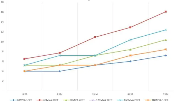
Figure 3.6 The price of the HTS cables by capacity and by distance Figure 3.7 The results of calculating the investment cost of a tri-axial
HTS cable and the cooling system by distance.
Figure 3.8 Path for superconducting wire cost reduction by volume
Figure 3.9 The structure of EBA terminations (a) for three phase in one cryostat HTS cable (b) for tri-axial HTS cable
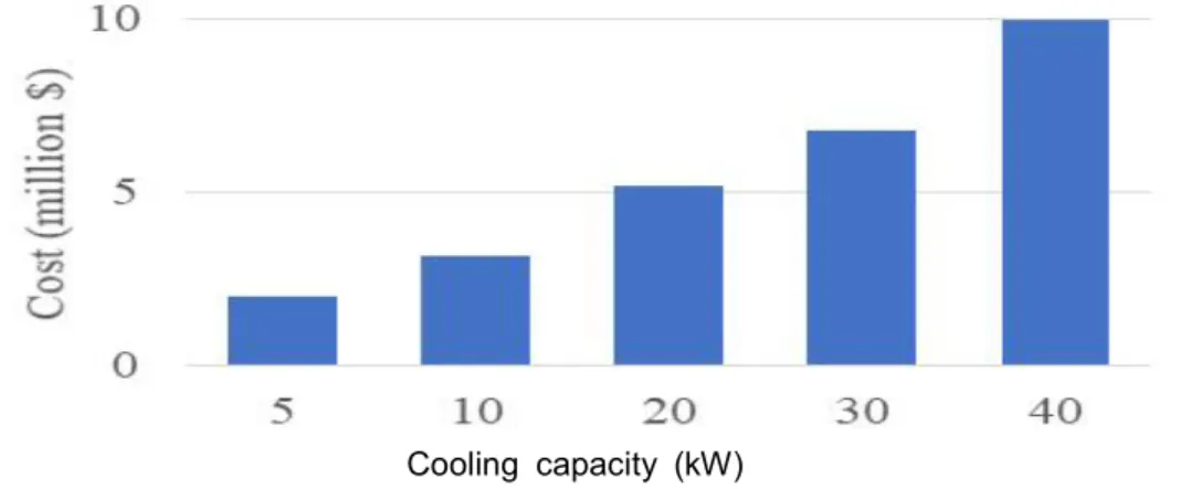
Figure 3.10 The investment cost of cooling system by cooling capacity based on a combination of 5 kW and 10 kW cooling systems Figure 3.11 The results of the cost estimates of the cooling system by the
23 kV tri-axial HTS cable capacity
Figure 3.12 The conventional method used to install substations in urban areas
Figure 3.13 The concept of a hybrid power system combined with 23 kV HTS power cables.
Figure 3.14 (a) the conventional method requires the construction of a new 154 kV substation at the center of loads (b) the HTS method requires only 23 kV switching stations
Figure 3.15 The substation can be relocated to the outskirts of towns by replacing 154 kV cables with 23 kV HTS cables Figure 3.16 (a) conventional method of substation relocation
(b) hybrid power system configuration with 23 kV HTS cables in conduits
Figure 3.17 The application of the HTS cables to connect the distributed energy resources(DER) including solar PV farm, wind farm, etc.
Figure 3.18 Conceptual diagram of conventional power system and proposed HTS power platform
Figure 3.19 The circuit number of 154 kV underground cables by length in KEPCO's power system
Figure 3.20 The load density distribution of substations by supply area
Figure 3.21 Layout of a small substation with two story building on the cross sectional area of 1,200 m2
Figure 3.22 Simplified layout of a 23 kV switching station with single story building on the cross sectional area of 180 m2
Figure 3.23 HTS power platform with three switching stations linked with 23 kV HTS cables, which is a new power system configuration for power supply in urban areas
Figure 3.24 The HTS power platform with two 23 kV switching stations linked with 23 kV HTS cables
Figure 3.25 The shape of an HTS power platform can be either ring type or line type. The ring type consists of HTS cable network fed from a single substation and 2-3 switching stations in the middle
Figure 3.26 A platform consisting of two stations with 120 MVA load supply capacity and every HTS cable connecting between stations has a capacity of 90 MVA
Figure 3.27 On a platform of two stations with 120 MVA capacity, the optimal number of lines can be five, not six
Figure 3.28 A platform consisting of two stations with 120 MVA load supply capacity and every HTS cable connecting between stations has a capacity of 120 MVA
Figure 3.29 A platform consisting of three switching stations with the same 120 MVA supply capacity and (a) with the 90 MVA HTS cables (b) with the 120 MVA HTS cables
Figure 3.30 First peak limiting resistor type superconducting fault current limiter (SFCL)
Figure 3.31 The SFCL can be divided into the first peak limiting type, and the first peak non-limiting type
Figure 4.1 Life cycle cost analysis (LCCA) includes investment cost, operation cost, and replacement cost
Figure 4.2 Application of 23 kV HTS cables to replace the 154 kV transmission cables and 154 kV substations
Figure 4.3 (a) The investment cost of conventional method and 90 MVA HTS cables by distance and the percentage of distance taken up by the cable tunnel
(b) The investment cost of conventional method and 120 MVA HTS cables by distance
13
Figure 4.4 The land price difference that makes the investment cost of the conventional method and the HTS only method the same when two 90 MVA HTS cables are applied
Figure 4.5 The land price difference that makes the investment cost of the conventional method and the HTS alone method the same when two 120 MVA HTS cables are applied
Figure 4.6 Total investment cost comparison between conventional and HTS cable application method considering the land cost $4 million of substation (distance 2 km and 3 km, respectively) Figure 4.7 If 23 kV HTS cables are applied rather than a bundle of
distribution feeders, less expensive conduits can be constructed instead of a cable tunnel
Figure 4.8 The investment cost by distance when two circuits of 120 MVA HTS cables are installed
Figure 4.9 The overall change in total investment cost due to land price changes
Figure 4.10 A 30-year load increase model and the sequential installation of 23 kV switching station for the two-station platform
Figure 4.11 The construction of the two 23 kV switching stations by phases based on the demand forecast for the two-station platform
Figure 4.12 A 30-year load increase model and the sequential installation of 23 kV switching station for the three-station platform
Figure 4.13 The construction of the two 23 kV switching stations by phases based on the demand forecast for the three-station platform
Figure 4.14 The total investment cost of HTS power platform based on the load supply capacity the capacity of 23 kV HTS cables
Figure 4.15 For the three-station platform, loop-type configuration seems to be more economical
Figure 4.16 For the two-station platform, radial-type configuration seems to be more economical
Figure 4.17 The comparison of the investment costs and BCRs between the two-station or three-station platform with the same load-supply capacity by the HTS cable capacity
Figure 4.18 Total investment cost of HTS power platform by the land price Figure 4.19 Cost comparison between conventional method and HTS power
platform
Figure 4.20 Cost comparison of 1 Go-1 Return and 2 Go-1 return
Figure 4.21 The total investment cost of the HTS power platform based on the load supply capacity and the capacity of 23 kV HTS cables according to the 23 kV switching station’s capacity Figure 4.22 The total investment cost of the three-station loop-type HTS
power platform by the capacity of 23 kV HTS cables
Figure 4.23 The total investment cost of the three-station radial-type HTS power platform by the capacity of 23 kV HTS cables
Figure 5.1 One cell of the 23 kV HTS power platform
Figure 5.2 The demonstration project of an 23 kV 60 MVA HTS power platform between KEPCO’s 154 kV Munsan and Sunyou substations
Figure 5.3 The configuration of a cooling system installed in the Sunyou substation to cool the superconducting cables on both sides together
Figure 5.4 The temperature and pressure profiles of a cooling system installed in the Sunyou substation
Figure 5.5 The configuration of the cooling systems installed separately in the Munsan and Sunyou substations to achieve higher reliability of power supply
Figure 5.6 The temperature and pressure profiles of the two cooling systems installed separately in the Munsan and Sunyou substations
Figure 5.7 Load flow analysis on the HTS powe platform based on KEPCO’s 8th long-term transmission expansion plan
15
LIST OF TABLES
Table 1.1 Number of public complaints and substation construction delay Table 1.2 Specification of hub-type 154 kV substation
Table 1.3 Specification of 23 kV HTS power cable system of the Shingal Project in south Korea
Table 1.4 The effect of sharing the supply capability between two substations during test operation
Table 2.1 The configuration of superconducting cables according to their structure including the improved tri-axial HTS cable with external return pipe
Table 2.2 Tri-axial HTS cable structure by LN2 circulation method
Table 2.3 Temperature and pressure difference by circulation method and by cable length of tri-axial cable
Table 2.4 Verification tests of HTS cables considering engineering factors Table 3.1 The total construction cost breakdown for a 154 kV substation with
a total capacity of 240 MVA
Table 3.2 The cost sample of purchasing the substation site by categories Table 3.3 The cost of the double circuit 154 kV XLPE cables by length Table 3.4 The construction cost of various underground facilities by distance Table 3.5 Cost breakdown of 23 kV tri-axial HTS cables(120 MVA, 3 CCTs) Table 3.6 The average construction cost of the small distribution transformer
stations in Myeong-dong, Seoul
Table 4.1 The values for 154 kV substation construction
Table 4.2 The amount of carbon emission per unit megawatt-hour based on 2011 data from the Korea Power Exchange
Table 4.3 The average emission trading price of the Korea Power Exchange between January and April 2019
Table 4.4 The economic indicators based on the land price when constructing a substation in the center of loads located 2 km away from existing substations
Table 4.5 The economic indicators based on the land price when constructing a 23 kV switching station connected with two 23 kV 90 MVA HTS cables
Table 4.6 The economic indicators based on the land price when constructing a 23 kV switching station connected with two 23 kV 120 MVA HTS cables
Table 4.7 The investment cost breakdown of two-station loop-type HTS power platform (120 MVA × 2 stations)
Table 4.8 The investment cost breakdown of two-station loop-type HTS power platform (150 MVA × 2 stations)
Table 4.9 The investment cost breakdown of three-station loop-type HTS power platform (120 MVA × 3 stations)
Table 4.10 The investment cost breakdown of three-station loop-type HTS power platform (150 MVA × 3 stations)
Table 4.11 The investment cost breakdown of three-station radial-type HTS power platform (150 MVA × 3 stations)
Table 4.12 The specifications of conventional method and the HTS power platform with the load supply capacity of 240 MVA
Table 4.13 The specifications of conventional method and the HTS power platform with the load supply capacity of 300 MVA
Table 4.14 The BCR and IRR of the two-station HTS power platform with the load supply capacity of 240 MVA
Table 4.15 The BCR and IRR of the three-station HTS power platform with the load supply capacity of 240 MVA
Table 4.16 The BCR and IRR of the two-station HTS power platform with the load supply capacity of 300 MVA
17
Table 4.17 The BCR and IRR of the three-station HTS power platform with the load supply capacity of 300 MVA`
Table 5.1 Six 154 kV substation candidate locations derived from the eighth long-term transmission expansion plan of KEPCO
Table 5.2 The result of the load flow analysis for the HTS power platform Table 5.3 The fault currents before and after the installation of the HTS
power platform
C HAPTER 1
INTRODUCTION
1.1 Electric power grid for an urban power supply
1.1.1 Rapid load growth and high load density in urban areas
Fig. 1.1 Trend of national power demand growth and urbanization
The Korean economy has achieved very rapid economic growth of more than 8%-10% a year since the 1960s. As a result, per capita GDP increased from only 12% of that of the U.S. in the 1970s to 62% in 2010. Along with economic growth, electricity demand has also increased significantly However,
Chapter 1. Introduction 2
the economic growth rate has decreased slightly since the 1990s, although it still appears to be higher than that of developed countries. As shown in Fig.
1.1, from 2005, the power demand and power demand growth rate graphs have still shown growth rates of 5%-8%. The electricity demand growth rate has decreased to below 5% since the 2010s; however, it is still growing at a very fast pace compared to that in advanced countries. Further, the peak demand has steadily increased from 85,153 MW in 2005 to 101,000 MW in 2016 [1]. In particular, power demand tends to be focused locally owing to industrial park development plans and urbanization. In addition, power demand growth is estimated to remain at 2%-3% for now owing to the increasing use of electronic devices in everyday life. The expected electricity demands must inevitably be accompanied by the construction of power plants and a grid construction plan to transmit them. Experts have predicted that the need for large power transmission networks could change thanks to the recent introduction of decentralized power sources; however, the reality is that power grids are more important than ever for connection and transmission with large renewable power complexes. In addition, the increased load density in urban areas due to urbanization necessitates the construction of power facilities to send more capacity. Technological developments in power systems inevitably focus on increasing capacity and improving efficiency. The government is also actively pushing for the expansion of traditional power facilities as well as the introduction of new technologies such as high voltage direct current (HVDC) and flexible alternating current transmission system for solving problems such as power transmission congestion that are caused by regional imbalances between supply and demand.
A long-term transmission expansion plan, including the construction of new substations and transmission lines, has been established based on various factors such as economic growth rate, population changes, urban development policies [1]-[2]. The construction of power facilities has been promoted so that loads can be supplied at the right time; however, during such a process, serious construction delays are often caused by public opposition, or the project
itself may be aborted. To overcome these challenges, attempts have been made to increase the size of the substation rather than increasing the number of substations; unfortunately, the projects were not carried out successfully because it was difficult to secure sites for large substations in the downtown area and to connect the several dozens of distribution feeders owing to the constraints on the land for power lines. These projects will be further described with lessons learned in the next subsection 1.2.
1.1.2 Increasing public opposition to construction of electric power facilities
Local residents’ strong opposition to the construction of electric power facilities has recently emerged as one of the biggest social issues. The frequent issues raised by residents are mainly noise, problems related to electromagnetic fields (EMF), and falling property values. However, ultimately, residents are very dissatisfied with the unsightly environmental degradation caused by power
Transmission line opposition grows
What drives opposition to high-voltage transmission lines?
Fig. 1.2 KEPCO’s plan for construction of high-voltage transmission lines is being met with mounting public opposition
Chapter 1. Introduction 4
facilities and its impact on real estate values. The new standard of social acceptability is important in this regard. The issues of social acceptability, and economic efficiency have been greatly highlighted recently as they call for the active resolution of residents’ complaints during the licensing process of local governments for all matters, such as new construction or extension of power facilities. To enhance social acceptability, KEPCO has established and applied measures to mitigate damage to residents and to compensate them financially.
However, they remain a long way from satisfying residents’ desires. Fig. 1.2 shows local residents’ opposition and the media’s coverage showing negative reporting attitudes.
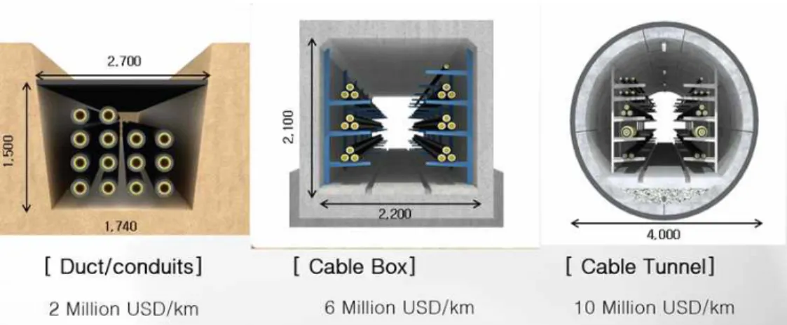
Residents’ opposition to the reduction of property value and environmental hazards in the areas surrounding power facilities often leads to arguments calling for an underground construction. Underground construction is largely divided into three types, as shown in Fig. 1.3. Direct burial or duct construction with the installation of conduits is the cheapest underground construction method; it costs around $2 million per km and has the advantage of minimizing the construction space. If the number of cables increases above 9 or 10, then duct construction cannot accommodate all the cables. In such cases, cable boxes should be installed with the open cut method. In some difficult construction environments, tunnel construction is inevitable when cable Fig. 1.3 Various underground structures for the installation of electric power cables
boxes are difficult to install, which requires construction at a depth of 60 m below ground level; further, the construction method requires the use of shield tunnel boring method (TBM), and therefore, the unit cost of construction is five times higher at approximately US$10 million. Around 20% of underground construction often requires cable tunnel construction owing to difficult construction environments such as river crossings, densely populated areas, or heavy traffic areas [3].
1.1.3 Strategies for improving social acceptability
Various measures are being considered and applied in practice to enhance social acceptability. While it would be a priority to devise such a method if a technological alternative could be found, it often poses the problem of excessive investment costs. Where necessary, financial support is available where financial compensation is sought. Fig. 1.4 shows a case in which the legal distance of compensation for support around a steel tower or substation is prescribed [4]. For the construction of the power line, support projects are carried out up to 1 km away from the transmission line, and for the substation, support is provided up to 850 m away from the substation. Houses located at a shorter distance are either purchased or land price compensation is
Right-of-Way Width
765kV : 1.000 m 345kV : 700 m Compensation
Compensation
765kV : 850 m 345kV : 600 m S/S Boundary
Fig. 1.4 Financial compensation area for the surrounding communities around the transmission lines or substations
Chapter 1. Introduction 6
offered. This process could reduce opposition to the construction of power facilities such as steel towers and simultaneously increase social acceptability.
Nevertheless, cases that still require an underlying construction or claim to change to a lower voltage reveal the increasingly difficult aspects of power facility construction projects. Fortunately, it is encouraging that the various new technologies that have been introduced in recent years can offer various measures on a case-by-case basis. For example, introducing new technology facilities, such as HVDC, may be effective at locations that inhibit fault currents or require long-range, high-capacity transmission. In the past, it was expected that the need for the extension of the transmission system may be reduced owing to the installation of distributed energy resources using solar or wind power; however, the demand for the grid has increased more than ever owing to the recent large-scale and distant deployment of new and renewable sources such as wind power. Fortunately, the introduction of smart grids along with the introduction of energy-saving energy storage systems suggests new possibilities to increase system efficiency, and it seems that the company has begun opening the door to a new paradigm for power systems. It is expected that the rapid development of superconducting technology will further enhance its usability in the power system while many diverse methods are being explored. In the next subsection, the superconducting cable technology that is gaining the most attention among superconducting technologies will be explained.
1.2 Challenge of hub-type 154 kV substation for an urban power supply
In this subsection, the progress made in the mid-2000s will be reviewed when the peak load increased very rapidly and substations were being constructed urgently. The construction of large-scale substations, called hub-type substations, was pushed forward to address power system expansion during this period. However, critical constraints during operations have left hub-type substation being abandoned. The lessons learned from the trials and errors caused by hub-type substations faced during their operations will be discussed [5].
1.2.1 Background of hub-type substation implementation
The need for stable power supply in areas with high load density, such as large-scale housing and industrial complexes, has increased over time. The introduction of a new concept of power supply with economies of scale was urgently needed to overcome opposition from residents and ease difficulties in securing substation sites. In 2007, the number of civil petitions per unit project and delayed completion date were increasing, as shown in Table 1.1, owing to a situation in which timely substation construction was becoming very difficult with the increasing difficulty of securing substation sites.
Year 2001 2003 2003 2004 2005
Construction opposition
number of petitions
per substation 1.25 1.45 2.12 3.19 3.90 number of petitions
per km of transmission lines
0.27 0.3 0.37 0.34 0.35
Construction delay
substations 15 18 22 22 24
transmission lines 10 13 15 14 16
Table 1.1 Number of public complaints and substation construction delay
Chapter 1. Introduction 8
In addition, construction conditions in areas with high load density were aggravated owing to the frequent construction of substations with average construction cycles of only 2-3 years. For example, the development of new towns in Seongnam and Bundang began in 1992 and was completed around 2008; further, a total of eight substations were built sequentially during this period, with one extension every 2.6 years on average. The development of the Ulsan industrial complex began in 1991, and five substations were built on average every 2.4 years until its completion in 2003. Hub-type substations were promoted as a way to overcome the difficulties of opposing residents and of simultaneously securing substations, and they highlighted the advantages of increasing the construction cycle to more than five years if two substations were built in the same place.
Fig. 1.5 Floor design of 154 kV Hub-type substation
1.2.2 Specification of hub-type 154 kV substation
The criterion for the construction of a new 154 kV substation is to establish a new substation if the expansion of the transformer is required at a substation with three banks installed. The fourth bank is a way to prepare for
uncertainties such as a sudden load increase. The supply capacity of a substation with three banks installed is considered to be 120 MVA when considering the N-1 reliability criteria of a single transformer. In comparison, hub-type substations were constructed in areas expected to exceed 200 MW, as shown in Fig 1.5. This is to deal with the case of one bank fault at a substation equipped with four banks of transformers with higher capacity than that of ordinary substations. Supply of 200 MW was considered enough for a population of 200,000 or an area of nearly 4,000 hectares. On the other hand, most large industrial parks have a much smaller area of ∼500 hectares. The load density of the new town is 4.5 MW/km2 and that of the industrial park is 44 MW/km2. This corresponds to the high-density subregion on the left-hand side of the load density curve. The supply of electricity in areas with high load density remains a major. Table 1.2 shows the specifications of the 154 kV hub-type substation. In fact, nine hub-type substations had been selected for installation in the Seoul metropolitan area, four of which have been constructed and are in operation.
Item Specification Item Specification
Transformer 8 banks
(60 MVA × 8) Shunt facility 40 MVar (5 MVar × 8) Rating of
circuit breaker 50 kA Connection
type
cable box (both directions) Number of
GIS bays
(Transmission) underground 8 (Distribution) underground 4
154 kV bus 4,000 A double-bus type Table 1.2 The Specifications of hub-type 154 kV substation
1.2.3 Lessons learned from hub-type 154 kV substation
The site of the 154 kV substation had an area of 3,300 m2, and the hub-type substation, which is equivalent to two substations, required an area of
∼4,400 m2, thereby reducing the required area by 34%. Economy of scale was
Chapter 1. Introduction 10
also realized in terms of the facility investment, resulting in a ∼30% reduction ($16 million) in the total investment cost. Despite achieving this economic feasibility, during actual operation, a very real challenge was faced with the 48-line connection to underground power lines. Large-scale cable box tunnel construction was carried out for connecting multiple power lines. In this process, a double cable box tunnel had to be built on both sides of the road;
however, getting government approval was very difficult and residents’
opposition never reduced. On the other hand, because the substation is not the optimal location for the extraction of power lines, excessive investment in underground construction could have occurred. These constraints have left the hub-type substations being abandoned, contrary to the hopeful expectations, and they have further affirmed that closer power facility planning cooperation between the distribution and the transmission sides is required. It is expected that hub-type substations will find a renewed role today if technological means are provided to address the route restrictions for the connection of power lines while achieving economies of scale to a certain level through the use of large-scale substations. In this regard, distribution superconducting cable technology, which can eliminate substations or accommodate multiple power lines in a single superconducting cable, seems very promising [7]-[10]. The next chapter discusses the current status of superconducting cable development and superconducting technology.
1.3 Recent progress of HTS power cable applications
Significant and rapid technical progress has been made in the area of high-temperature superconductivity (HTS) since its discovery in 1986. HTS wire and power system application developments have progressed toward technology commercialization, and large demonstration projects have been conducted for several applications. The application in which superconductivity has the potential to be effective in an electric power system can be separated into two general classes. The first class includes cables, motors, generators, and transformers where superconductors replace resistive conductors. The second class includes technologies that are enables by superconductivity and those have little, or at most limited, capability if conventional materials are used. Examples of such technologies are superconducting magnetic energy storage (SMES), fault-current limiters (FCLs), and fault-current controllers (FCCs) [11].
Fig. 1.6 shows the technology readiness levels for various power system applications. The vertical axis units provide a relative scale of the number of
Fig. 1.6 The HTS technology readiness levels for the various electric power application
Chapter 1. Introduction 12
projects. For instance, there are more superconducting fault current limiter (SFCL) and cable projects than there are other applications [12-13]. This part outlines the current state of HTS cable applications worldwide and describes the commercialization project of 23 kV HTS cables in South Korea.
1.3.1 Progress of HTS power cables worldwide
Superconducting cables have been developed for application to power systems owing to their continuous technological innovation and price reduction.
Several demonstration projects have been conducted worldwide to promote the availability of superconducting cables.
Generally, distribution superconducting cables are of the three-phase bundle type and three-phase superconducting cable cores are contained in one cryostat.
In transmission superconducting cables, each phase superconducting cable core is contained in a separate cryostat. To realize the economic advantages of HTS power cables, as a new concept of 23 kV HTS power cables, tri-axial cable
Fig. 1.7 Demonstration of 275 kV/3 kA 30 m-HTS cables in China
was proposed. Tri-axial superconducting cables in which superconducting conductors of each phase are arranged on the same central axis to reduce superconducting shield wires, are emerging as the next generation of power distribution superconducting cables. Development of tri-axial superconducting cables has already begun in many countries, and some countries and organizations have completed development testing and are working on the installation of a real grid system connection [7]. Countries and organizations around the world have been developing and operating various types of superconducting power cables to meet future demands for electricity. Fig. 1.8 shows HTS power cable projects worldwide [11].
Fig. 1.8 Worldwide HTS power cable projects
Chapter 1. Introduction 14
1.3.2 Progress of HTS power cables in south Korea
Over two decades, superconducting cable systems has been developed and demonstrated in Korea under government sponsorship with collaborating among joint industrial-academic research laboratories, national research institutes, corporations and KEPCO, as shown in Fig. 1.9. The related industry and academia in Korea have made urgent efforts to accelerate the development of HTS cable system, which has been proven through long-term research and demonstration projects. The following is an excerpt from the author’s study[6].
Simultaneously, the promotion of price reduction of HTS cables and the development of HTS cable markets also need to be coordinated. From June 2001, the R&D projects for realizing HTS power system application has been started with the name of Development of Advanced Power system by Applied Superconductivity technologies (DAPAS) Program.
Fig 1.9 Demonstration projects of 23 kV and 154 kV HTS AC power cables and 80 kV HTS DC cables in actual power systems, including the 154 kV Icheon and Jeju substations, were conducted and completed successfully in South Korea
In addition, Since 2008, the pilot demonstrations has been successfully performed through Icheon and Jeju Projects including AC 23 kV and AC 154 kV as well as DC 80kV class HTS power cables [14-19]:
● AC 23kV 50 MVA at Icheon substation
● AC 154 kV 600 MVA and DC 80kV 500MW at Superconducting power apparatus center in Jeju
Based on those demonstrations, Korea Electric Power Corporation (KEPCO) which is only electric utility in Korea has launched a plan to commercialize AC 23 kV HTS cables in actual grid, called the Shingal Project. Now, commercial operations are ready to start. In particular, through the Shingal Project, the Korean HTS society is proud to have received the honour of being recognized as the first country in the world to deploy a commercial HTS AC power cable [20-21], and is pursuing the challenge of this new technological expansion as it will have great significance worldwide. Further, the authors expect that the success of this commercial project to contribute greatly to introduce the new trend of superconducting power grid in the future.
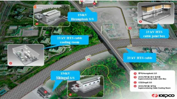
In this project, AC 23 kV 50 MVA cable system composed of 1 km long cable, two sets of normal joints and two sets of terminations as well as cryogenic cooling system with 10 kW capacity have been installed between AC 23 kV distribution busbars of 154 kV Shingal and Heungdeok substations, as shown in Fig. 1.10.
Table 1.3 lists the configuration of the 23 kV 50 MVA HTS cable system and triad type HTS cable applied in this project. The 23 kV HTS power cable system in the Shingal Project had a rated a capacity of 50 MVA, rated current of 1,260 A, and nominal voltage of 22.9 kV for the distribution line. This cable was divided by three spans by considering transportation regulation and interval of existing underground structure and approximately 150 km HTS wire has been employed. Especially, at the design stage, two different kinds of HTS wire have been determined to be applied for satisfying manufacturing schedule.
For the first and the third span from Shingal substation, the second generation (2G) wires, i.e. ReBCO, and for the middle span generation (1G) wires, i.e.
Chapter 1. Introduction 16
BSCCO, have been employed, as described in Tables 1.3 and 1.4.
Each span of cable have spliced via jointing material inside of normal joint without direct contact of wires of each cable span. Therefore, there was no physical and electrical malfunction to transmit load current in entire length of cable because the ratio between total rated current and critical current is designed to maintain below 50% to reduce in normal condition even though the critical current of two types’ of HTS wire is a little different. However, manufacturing process, jointing methods are slightly different. This differences are expected to be a useful comparison in terms of reliability as well as cable maintenance during long term operations.
Fig. 1.10 A 23 kV HTS cable system configuration of the Shingal Project in South Korea
Items Unit Specification
Rated capacity MVA 50
Rated current
/nominal voltage kA / kV 1.26 / 22.9
HTS power cable type Triad configuration
Total length of HTS cable m 1,035
Number of joints EA 2
HTS tapes 1G / 2G
Total length of the HTS
wire used km 150
Cooling System Design kW
7.5kW@69 K Turbo-Brayton and
decompression Operation Condition
(Temperature and Pressure) K, bar-g 66~77K, under 10 bar-g Operation Condition
(Mass Flow Rate) Kg/s 0.4~0.6
Table 1.3 The Specifications of 23 kV HTS power cable system of the Shingal Project in South Korea
Specification YBCO (2G) BSCCO (1G)
Min. DC Ic (@77.3K,sf) 150A 170A
Dimension (W×T) [mm] 4.4 × 0.35 4.4 × 0.35
PLY 3-PLY 3-PLY
Table 1.4 Specification of applied HTS wires
Chapter 1. Introduction 18
Fig. 1.11 A block diagram and 3D design of the cooling system configuration for the 23 kV HTS power cable in Shingal Project
The cooling system composed of Turbo-Brayton refrigeration system with about 10-kW cooling power as a primary use and an open-loop decompression unit as a backup with the same cooling power has been installed to maintain the stable operation of the HTS cable system. Especially, it is the first application of large cooling power system to prepare long distance HTS cable system similar to the conventional cable’s application. Fig. 1.11 shows a system composition diagram with instruments and a three-dimensional illustration of the cooling system.
The performance test result on cooling system to verify its the design value of 10 kW at 70 K has been carried out by artificial load test, as depicted in
Fig. 1.12 The cooling performance test results of the product refrigerator
Fig. 1.12. In this test, the coefficient of performance (COP) of the refrigerator on the HTS power cable was measured to be 0.059 at 70 K.
After starting the construction of the cooling system installation in Oct. 2017 and signing a contract with LS Cable in Mar. 2018, the superconducting cable installation began in Oct. 2018. In Nov. 2018, the cooling system was completed and the test run was conducted. After the bobbin test of the conduit, HTS cables were installed from Dec. 2018. There was an empty conduit along the cable route between the Shingal and Heundeok substations; therefore, no conduit construction cost other than cable installation costs was incurred.
Starting in Mar. 2019, the installation and commissioning test of the cooling system monitoring system were conducted, and vacuuming and liquid nitrogen circulation cooling of the cables began. In September 2019, the trial operation for two months was completed successfully. Now, it’s in operation.
Figs. 1.13 and 1.14 show the cable, joint boxes and termination installation for the Shingal project. The 23 kV HTS cables can be installed using conventional cable pulling techniques.
Fig. 1.13 A 23 kV HTS cable installation and joint works at Shingal substation (M/H #1 – M/H #3 section)
Chapter 1. Introduction 20
Fig. 1.14 Normal joint box and termination were installed
1.3.3 Commercial operation of 23 kV HTS power cable
Project motivation is briefly described as follows. Shingal is the name of the residential district which is expected getting population in growth. For this reason, KEPCO had to build a new substation in Shingal area to transmit more power to this area because the existing Shingal substation was already full-banked. By contrast, Heungdeok substation around 1 km away from Shingal substation has two extra places for additional transformers.
In this regards, KEPCO considered to apply 23kV HTS cable by connecting 23 kV bus bars between substations instead of conventional 154 kV underground cable by installing a 154k V step-down transformer in Heungdeok substation as a result from the case study between two solutions comparing HTS application and conventional one. By analyzing economic evaluation between two cases, KEPCO figured out that HTS cable application is cheaper than the conventional cable application by cutting the project cost as 15%p and which was the main reason to proceed this project.
Power system operation and protection schemes has been reviewed when the two substations were linked with the 23 kV HTS cable, as shown in Fig. 1.15.
For the reason that the 154 kV Shingal substation has loads of upto 162 MW compared to the 49 MW load of the 154 kV Heungdeok substation, it is expected to share some of the Shingal substation’s load through the HTS power cable with the Heungdeok substation. However, considering that this is the first use case of the 23 kV HTS cable in an actual power system and that
#4 transformer at Shingal substation has been connected to two feeders and the load of one feeder will first be supplied through the HTS cable and further load sharing will be considered in the future.
Operation measures also have been established for contingency cases of HTS cables, breaker failure, and bus failure. Further, the installation of bus section breakers has been reflected for stable and efficient system operation in case of HTS cable system failure or maintenance.
AC 23kV HTS cable connection is planned to have the effect of sharing the supply capability between the two substations. In addition, emergency supply through the HTS cable will be possible during a complete blackout of AC 154 kV Heungdeok substation. In the past, two simultaneous failures of AC 154 kV transmission lines led to a blackout of AC 154 kV Heungdeok substation, Fig. 1.15 Power system operation and protection schemes were reviewed when the substation was linked with the 23 kV HTS cable
Chapter 1. Introduction 22
Fig. 1.17 The temperature and pressure of the 23 kV HTS power cable in real operation from July 16 to Sep. 14, 2019
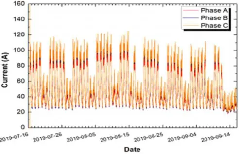
Fig. 1.16 The current curve of the 23 kV HTS power cable in real operation from July 16 to Sep. 14, 2019
resulting in an outage of up to 49 MW. Now, the system reliability has been greatly improved as power can be supplied through HTS cables before recovering the transmission lines.
The operation current of the 23 kV HTS power cable for 2 months was shown in Fig. 1.16. The temperature and pressure curves were confirmed to be maintained well for over 2 months of test operation, as shown in Fig. 1.17.
The inlet and outlet temperatures were measured to be almost 69 K and 71 K, respectively. The inlet and outlet pressures were also stable from 6.3 bar,g to 6.4 bar,g. In terms of the specific heat of LN2 and mass flow rate of 0.5 kg/s, the temperature differences of 2 K between cable inlet and outlet means a heat loss of 2 kW, therefore it is possible to verify that the system is operating very satisfactorily.
1.3.4 Challenges preventing massive adoption of HTS cables
Although more than 30 years have passed since the discovery of high temperature superconductor in 1986, many technical challenges remain. Cost and economics are unquestionably the greatest challenges. The basic metric used to assess how cost-effective HTS wires, and consequently, HTS cables, is the cost per kiloampere-meter. This is because higher critical currents result in less HTS wire needed for the same power transfer. For now, HTS cables have cost in the range of a few 100 $/kAm; this makes HTS solution uncompetitive from cost viewpoint because the corresponding cost for copper and other conventional cabling materials is still a fraction of this value [12][22-23].
The price of cables per unit transmission capacity applied at the actual site seems to be $3,000 for the 154 kV XLPE cables and around $19,000 for the CNCE cable, which is most commonly applied as a 23 kV distribution feeder.
These values are the average values obtained from KEPCO’s purchase statistics.
In comparison, the three phase in one cryostat (or triad type) 23 kV HTS cable costs $110,000; this is around six times higher than the cost of conventional power distribution cables.
The price of superconducting cables, which is an important variable to
Chapter 1. Introduction 24
determine their economic status, is closely related to the growth of the cumulative sales volume of superconducting cables, and the growth of this market can be expected to fall in the future. For example, data released by the Yano Economic Research Institute in Japan showed that Japan’s superconducting cable market is likely to grow rapidly in the future and reach 150 billion yen by 2030. Nonetheless, before market expansion, how to cross the cable length barrier and how much the price of the excessively expensive HTS cable can be lowered remain unclear, as shown in Fig. 1.18 .
Cooling is another significant cost component, even with LN2 systems, because cooling requirements and refrigeration costs are high. Although cryogenics has steadily advanced to provide higher efficiency at lower cost, the HTS power industry is still too small to achieve enough manufacturing scale for realizing a significant cost impact [13].
Fig. 1. 18 Projects of HTS power cable (Length vs. Voltage)
1.4 Objectives and contributions of this study
When constructing a new substation, it is advantageous to construct it at the center of the loads for loss minimization; however, it is not easy to secure a substation site in urban areas with high load density owing to the very high land prices, complex permission processes, and social acceptability issues. This has led to an increase in investment costs, either owing to the failure to construct a substation in a timely manner or the need to relocate the substation outside urban areas.
The advantage of superconducting cables, which have been rapidly developed in recent years, is their capability to transmit 5-10 times more capacity than those of feeders of the same size, making them an excellent means of avoiding building new substations and replacing transmission cables. Given these advantages, studies on how to utilize superconducting cables are required in high load density urban areas where installing new substations and transmission cables is hindered by mounting public opposition.
The author has conducted a study to supply power to urban areas using 23 kV HTS cables and proposes a new power system model called the HTS power platform to prove the method’s feasibility. This platform refers to the new configuration of an electric power grid composed of two to three 23 kV switching stations connected with each other by the 23 kV HTS cables in urban areas with high load densities and land costs. The size of the 23 kV switching stations is only 20%-30% of that of the conventional 154 kV substations.
However, the disadvantage of the conventional HTS cable (three phases in one cryostat; triad type) is that it is not easy to utilize further owing to its high investment cost. As an alternative, the development of tri-axial HTS cables without using HTS shield wires, such as those used in the AMPACITY project in Germany, enables cost reductions, but a limitation of the cooling system keeps the HTS cables from exceeding a length of 1 km. Thus, technical improvements in tri-axial HTS cables are needed to configure the HTS power platform.