© 2021 The Japan Society of Mechanical Engineers [DOI: 10.1299/jamdsm.2021jamdsm0033]
Paper No.20-00484
Effect of particle restitution coefficient on high-power gear
transmission with dynamic continuum and non-continuum
coupling
Wangqiang XIAO*, Wenyu SHAO*, Jinsong SHI*, Yuanyi LUO** and Sheng WANG***
1. Introduction
With the development of mechanical transmission systems, high-speed and high-power gear transmissions will have higher requirements on vibration reduction and service life (Chen, Z.G. and Y.M. Shao, 2013). In transmission systems, internal excitations are caused by the periodic alternating meshing of single and double teeth (Hu, Y.M., J.K. Fan, and J. Yu, 2016). The internal excitations consist of meshing stiffness (Ambarisha, V.K. and R.G. Parker, 2007), transmission errors, and impact force (Chen, Z.G. and Y.M. Shao, 2011), which are the primary causes of vibration on gear meshing (Ma, H., et al., 2015; Parey, A., et al., 2006). External excitations induced by the prime mover and load can also lead to vibration (Tuttle, T.D. and W.P. Seering, 1996). Moreover, the vibration of the gear system is related to each component’s structural form; thus, the gear transmission system has high nonlinearity and a coupling effect. The restriction of vibrations on the development of high-end gear devices requires urgent solutions.
Active vibration damping and passive vibration damping are two main vibration damping methods of gear system. For the active vibration reduction of gear, it is mainly to optimize the parameters of gear design and improve the machining accuracy of its own, but it will also bring about a large increase in the manufacturing cost (Dion J.L.,Moyne S.L. and Chevallier G, 2009; Li, Y.N., et al., 2014). In the aspect of active vibration reduction (Chen, S.Y., et al., 2014; Bonori G, Barbieri M and Pellicano F., 2008), the modification of gear was carried out, and various optimization design methods were combined to achieve the purpose of modification and optimization design, so as to reduce the meshing
*School of Aerospace Engineering, Xiamen University, Xiamen 361102, China
E-mail: [email protected] **Xiamen Zhenwei Technology Co.,Ltd,
Xiamen 361102, China
***Beijing Institute of Electronic System Engineering, Beijing 100854, China
Received: 17 November 2020; Revised: 18 January 2021; Accepted: 14 May 2021 Abstract
High-power gears are widely used in various engineering fields. A gear transmission system is an extremely complex elastic system that produces complex vibrations under internal and external excitation. In this study, the excitation value in the gear was obtained based on the dynamic characteristics, stiffness, and error excitation, which were used as the input signals of the discrete element analysis. The dynamic model of the gear transmission system was established using the discrete element method. Meanwhile, the gear transmission energy was dissipated through the configuration of a particle damper in the gear. The continuous-discontinuous dynamic coupling method, which is the equivalent displacement mapping of gear contact loads from the discontinuous domain to the continuous element node, was realised, and the transformation of the local coordinates to the global coordinates was conducted. Finally, the effect of the particle restitution coefficient on the vibration reduction of gearboxes at various speeds was explored and verified through an experiment. At low rotating speeds, the best vibration reduction effect was achieved when the particle restitution coefficient was 0.2. At high rotating speeds, the best restitution coefficient was 0.7.
vibration between gear teeth. In the aspect of passive vibration reduction (Peng, N, et al., 2014; Dogruer. C.U. and Pirsoltan A. K., 2017), various shock absorbers and damping rings were designed to reduce the vibration of the gear.
In the vibration reduction analysis of the gear system, active vibration reduction must increase the processing accuracy. Meanwhile, the parameters of the gear transmission system require redesigning, which has many limitations such as sizeable computational complexity and high processing cost. A more efficient method called particle damping (Bai, X.M., et al., 2009) has been adopted as a new passive vibration-reduction technique, and it is based on the theory of energy dissipation (Panossian, H.V., 1992). In the analysis of passive vibration reduction, the energy generated by the vibration of gear transmissions can be effectively consumed by producing damping on the transmission path of the wave. Subsequently, the vibration transfer can be reduced. Particles are used as a damping media to fill the interior cavity of the structures with granular matter (Xu, Z.W., M.Y. Wang, and T.N. Chen, 2005). The damping effect is provided by friction and inelastic collisions between particles and the wall of the container. Vibration is caused by gear meshing and wear transmitted outward in the form of wave propagation; therefore, many transmission paths may occur. The typical one is linear vibration from the tooth surface→ lightening holes→ shaft→ bearing→ bearing block→ gearbox (or torsional vibration from tooth surface→ shaft).
Particle damping is widely used in the steady-state field, but it has not been extensively studied in the centrifugal field, particularly in gear transmission. In previous studies (Xiao, W.Q., et al., 2016), we established a contact model of discrete particle elements in gear pairs and explored the energy dissipation mechanism caused by particle friction and collision motion in the centrifugal field of gear transmission. However, in the study of the dynamic behaviour of high-power gear transmission systems, the finite element method (FEM) is generally used to analyse the dynamic response of the gear. Previous reviews could not directly link the energy dissipation of particles with the finite element model to solve the displacement and stress at different positions of gear transmission using particle damping. Therefore, we proposed a new concept of modelling called continuous-discontinuous multi-body coupling, in which the gear is a continuum and the particle is a non-continuum (Desrues, J., et al., 2019). The discrete element method (DEM) (Kruggel-Emden, H., et al., 2008) was used to discretise a discontinuous body into independent elements, and the motion equation of each aspect was solved using the time-step iteration method (Burns, S.J. and K.J. Hanley, 2017). In the soft sphere model, the contact force (Di Renzo, A. and F.P. Di Maio, 2004) was calculated using the overlapping contact particles, and the motion and position of all particles were updated at each calculation time point. Subsequently, through finite element analysis, the gear with continuity was decomposed into a combination of small elements. Finally, we accomplished the aim of the unknown field by calculating each element with the assumed approximate service, which transformed the infinite-degree-of-freedom problem of the continuum to a finite-degree-infinite-degree-of-freedom problem (Onate, E. and J. Rojek, 2004). The new motion obtained by the finite element simulation was used as the motion excitation input of the discrete element to establish the vibration reduction model of the gear particle damper according to an actual application (Rougier, E., A. Munjiza, and N.W.A. John, 2004).
The key factors of particle damping are particle diameter, material, friction coefficient, and restitution coefficient, and the damper’s filling rate. We changed the surface restitution coefficient by changing the material of the inner surface of the damper (Wang, P., et al., 2015). This paper predicts the dynamic behaviour of the gear transmission of a particle damper through the coupled DEM-FEM calculation method because the restoring coefficient of the particle surface directly affects the motion state of the particle after collision. The method also reveals the entire process of contact-energy dissipation-particle force chain reconstruction between the particle medium and gear structure. The optimal allocation method of the damper and particle for a high-power gear transmission system under particular operating conditions is solved. This method was verified using a gear dynamic test bench. Finally, the solution of vibration control for a high-power gear transmission system based on the continuous-discontinuous multi-body coupling is obtained.
2. Dynamic model of gear meshing
2.1 Gear Meshing Motion Equation
To obtain the motion characteristics of the particles in a damper configured with the equipment in a centrifugal force field, we must calculate the dynamic characteristics of the apparatus under general operating conditions. Because the dynamic trademarks of gears are different at various speeds and loads, the damping effect of damper particles changes accordingly. We must set various possible operating paces to obtain energy dissipation characteristics under various operating conditions to provide a reference for engineering practice.
© 2021 The Japan Society of Mechanical Engineers [DOI: 10.1299/jamdsm.2021jamdsm0033]
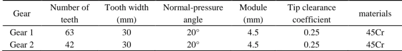
the elastic modulus of the gear is E1 = E2 = 206 GPa and Poisson's ratio is v1 = v2 = 0.3. Both sides of the gear contain eight through holes with a diameter of 15 mm and four thread holes with a diameter of 4.5 mm.
Table 1 Geometric parameters of gear pairs.
Gear Number of teeth Tooth width (mm) Normal-pressure angle Module (mm) Tip clearance coefficient materials Gear 1 63 30 20° 4.5 0.25 45Cr Gear 2 42 30 20° 4.5 0.25 45Cr
2.2 Damper design
To facilitate installation and disassembly, we designed a damper according to the gear parameters, and it was shaped like a cylinder with a diameter of 25 mm. The interference fit of the middle face, air vent, and ends of the cylindrical end face were carefully matched with the gear’s side to ensure the axial constraint of the shock absorber. During the experiment, damping particles of various diameters were filled in the damper. For the operability of the operation, the damping particles filled in the damper in this study had a single diameter.
Fig.1 Assembly mode and force. The normal force can be simplified as a spring-damper pair through a linear contact model. The tangential force can be simplified as spring-damper and sliding friction damper models to calculate it by using the Coulomb friction model.
Contact between particles generates regular forces through collision and tangential forces through friction. Figures 1 and 2 depict the gear with the particle damper in the lightening hole and the contact force model between the particles and between the particles and the damper wall, respectively.
The energy consumption of particle damping primarily includes collision and friction energy consumption. When particles i and j collide, in the presence of a normal force and restitution coefficient (e), the collision of particles will consume vibration energy.
Equation 1 can be obtained from the laws of conservation of momentum and energy:
' ' 2 2 ' 2 ' 2 1 1 1 1 2 2 2 2 + = + + = + + i i j j i i j j i i j j i i j j e m v m v m v m v m v m v m v m v E
(1)
where mi and mj are the masses of particles i and j, respectively, vi and vj are the velocities of particles i and j before
collision, respectively, vi’ and vj’ are the velocities of particles i and j after collision, respectively, and Ee is the energy consumed when the particles collide.
According to the definition of the restitution coefficient,
1 2 ' ' 1 2 v v e v v − = − (2)
Therefore, the following equation can be obtained:
(
2)
2 1 2( ) = − + i j e i j m m E e v m m(3)
Therefore, the restitution coefficient of the particles will affect the damping energy dissipation.
The surface restitution coefficient was changed by changing the material of the inner surface of the damper. The restitution coefficient of the particle surface will affect the motion state of the collision and friction in the damper, so it will affect the energy consumption of collision and friction.
Fig.2 Gear transmission vibration system. The driving gear is on the left and the driven gear is on the right. Both gears are connected to the shaft and can only rotate about the axis.
The gear is excited by the external acceleration impact and by the internal excitation caused by the gear stiffness excitation, error excitation, and meshing impact excitation, resulting in radical movement. The effect of the damping particles on the gear can be considered to be the external damping force caused by the gear system under the existing boundary conditions.
The dynamic model of the gear is also shown in figure 2. Subsequently, the nonlinear dynamic equation of the gear can be expressed as
( )[ ( )] ( )
+ + + s+ =
p + sMx Cx k t x x e t F t F
(4)
where M is the equivalent mass of the gear pair; C is the damping coefficient; k(t) is the time-varying mesh stiffness; e(t) is the integrated error of the gear, including the tooth shape and base common errors; 𝐹𝑝(𝑡)is the damping force of the particle system; 𝐹𝑠 is the external load; 𝑥𝑠 is the static relative displacement; and 𝑥̈, 𝑥̇, and 𝑥 are the vibration acceleration, velocity, and movement, respectively.
The equivalent excitation error is introduced, and a small amount is omitted. Subsequently, the nonlinear dynamic equation of the gear is described as follows, and k is used to represent the average mesh stiffness and the variable stiffness of the gear stiffness.
( ) ( )
p
Mx+Cx+kx=
F + k t e t(5)
Let p (t) be the internal excitation of the gear meshing; therefore,
( ) ( ) ( )
p t = k t e t
(6) Thus, this equation indicates that the more significant the change in the mesh stiffness of gears or the greater the error of the gears, the higher the meshing excitation. The particle damping forces act as the external excitation of the gear and adjusts its phase to reduce the internal excitation to achieve vibration reduction.
3. Method of coupling the continuum and non-continuum
3.1 Theory of the coupling method
We consider a gear as a continuum and a particle as a non-continuum to perform continuous-discontinuous multi-body coupling modelling. The DEM is based on Newton's second law of motion rather than on the principle of minimum potential energy. By distinguishing a body into independent tiny elements, the motion equation of each infinitesimal element can be solved using a time-step iterative method. Based on the centrifugal field particles under the action of a three-dimensional discrete element contact model, in a softball model by the amount of overlap between particles to make contact to calculate contact force, the particles in the gear cavity and inelastic collision and friction force of the structure of statistics and vectors, particles on the structure of the resultant force are obtained, and the data matrix is the input of the finite element analysis.
When the resultant matrix of the particle to the structure calculated by the discrete element is input into the finite element analysis, the data coupling part must ensure the consistency of the model and accuracy of the force input. Therefore, the contact load must be transferred from the discrete element load in the discontinuous domain to the equivalent displacement mapping of the gear finite element node forces, and the local coordinates must be transformed to global coordinates.
© 2021 The Japan Society of Mechanical Engineers [DOI: 10.1299/jamdsm.2021jamdsm0033]
3.2 Discrete Element Calculation of Gear Transmission
To realise the coupling of DEM and FEM, we must ensure that the geometric unit cell in the discrete element calculation corresponds to the finite element calculation of the grid cell, i.e., the unit IDs and node numbers are the same. Therefore, the mesh uses third-party software, adopts hexahedron mesh units, and is based on the model geometry definition of mesh size and density degree.
According to the interaction between the elements and Newton's law of motion, the DEM involves using a dynamic relaxation method to perform the cyclic iterative calculation (Kuo, H.P., et al., 2002), updating the location of the element at each time step, and traversing the entire set of elements (Mao, K.M., et al., 2004). By tracking each particle unit’s micro-motion, the force of each unit on the structural system is considered, and the effect of damping particles on the gear is calculated. For a single particle element in any coordinate axis and at any moment, translation and rotation are generated by the force acting on each element.
According to Newton's second law, for particle i:
( ) ( ) ( ) i i i i X t F t X t g t m = = −
(7) ( ) ( ) ( ) i i i i t M t t t I = =
(8)
where 𝑋𝑖 is the displacement vector of the centre of particle i, 𝐹𝑖 is the resultant force of the contact force acting on particle i, 𝑚𝑖 is the mass of particle i, g is the acceleration of gravity, 𝜃𝑖 is the angular displacement vector of particle i, 𝑀𝑖 is the net moment acting on particle i, and 𝐼𝑖 is the moment of inertia of particle i. The acceleration at time t can be expressed as [ ( ) ( )] ( ) i 2 i 2 i t t X t X t X t t t + − − = (9) [ ( ) ( )] ( ) i 2 i 2 i t t t t t t t + − − = (10)
Equations (11) and (12) can be obtained from Equations (9) and (10): ( ) ( ) ( ) ( ) 2 2 i i i i F t t t X t X t g t m + = − + − (11) ( ) ( ) ( ) ( ) 2 2 + = − + i i i i M t t t t t t I (12)
Thus, after time ∆𝑡, particle i arrives at a new position and generates new contact forces and contact torques; thus, it generates new accelerations and angular accelerations and continues to traverse the cycle.
When two particles are deformed because of contact, the alternating stress causes the contact surface to generate Rayleigh waves, which propagate along the surface of the particles. Experiments have demonstrated that most of the energy consumed by particle collisions emanates from the Rayleigh waves. Therefore, when selecting the time step in the simulation, it should be less than the time required for Rayleigh waves to pass through the hemisphere.
0.163 0.877 R R R R T V v G = = + (13)
where
is the particle density, R is the particle radius, G is the shear modulus, and v is Poisson’s ratio. In practice, the rated time step is approximately 20%–40%. In this study, 20% of the Rayleigh time step is selected as the time step of the discrete element calculation.3.3 Discrete Element Calculation of Gear Transmission
The particle system is discrete, and the DEM is used to calculate it. The gear is a continuous element, and the FEM is used in the calculation. For the coupled DEM-FEM calculation method, the basic concept is to consider the particle system as several discrete elements. First, the DEM is used to calculate the gear excitation and damping force of the structure of the particle system, and then the gear damping force is obtained. The damping force of the particle in the entire simulation process is obtained by repeating the steps. The finite element coupling calculation must transform the damping force of the node load. Based on the method of shape function, the local coordinate transformation of the shell element, unit load of the surface, and transformation of the triangular element node force are determined. The transformed
nodal forces are used as the computational boundary of the dynamics of a new gear system. Table 2 Force of the collision between particles and shell elements Unit
ID
Position coordinates Normal Force (N) Tangential Force (N)
X Y Z X Y Z X Y Z 22 0.0095 0.0088 -0.1395 -1.0824 0.1587 0.8457 0.1569 0.0881 0.1843 63 0.0094 -0.0077 -0.0738 -1.4535 0.4774 0.2551 0.0524 0.2438 -0.1570 115 0.0142 -0.0084 -0.0796 4.0981 -5.4405 3.2415 -0.5992 -0.9461 -0.8301 148 0.0121 -0.0291 -0.1167 1.1415 0.4576 -0.0666 -0.0331 0.0508 -0.2210 232 -0.0007 0.0341 -0.1013 0.2315 -0.7999 -1.0536 -0.2526 -0.0386 -0.0262 372 0.0146 -0.0261 -0.1151 -0.8968 -3.0739 -2.7778 0.4760 0.3430 -0.5334 … … … …
Based on the element ID number, the particle damping force on each element ID is synthesised in the local coordinate system, and the force on each shell element is calculated (Table 2).
The discrete element software can output the contact force of particles acting on the triangular boundary element. The finite element analysis of the equivalent concentrated load (force and torque) is frequently applied to a node. During discrete element analysis, the particle can also be selected as the contact point element node, but this requires the minimum and discrete element boundary meshes. During loading, each part of the triangle may have multiple contact points. Therefore, the force acting on the contact structure of particles should first be converted into the equivalent node force of each element. Here, the concept of the shape function is used for conversion. The general conversion process is shown in Figure 3.
Fig.3 Contact force conversion diagram of tetrahedral elements. Figure shows a triangular plane element with three nodes and the contact force of m particles acting on the triangular element. The figure represents a local coordinate system (x, y, z) at the centre (P) of the x-y plane, which is consistent with the plane of the triangular element. 𝑢𝑖𝑗 is the unit vector connecting points i and j, and 𝑢𝑖𝑘 is the unit vector connecting points i and k.
The triangular mesh can express any responsible boundary surface and simultaneously ensure the computational efficiency of the contact search. Many triangular elements frequently represent the boundary surface, and each triangular element has several particles in contact with it. The unit normal vector of plane triangular elements 𝑛̅ is as follows:
ij ik ij ik
u
u
n
u
u
=
(14)The local coordinate system of the x-direction consistent with u𝑖𝑗, local coordinate system 𝑢⃗⃗⃗⃗ , 𝑢𝑥 ⃗⃗⃗⃗ , 𝑢𝑦 ⃗⃗⃗⃗ can be 𝑧 expressed as
, ,
x ij y x z
u =u u = n u u =n (15)
The relationship between the local coordinate system and the global coordinate system is
x y z
, ,
T=
T
trans,1
X Y Z
, ,
T (16)
Ttrans,1
=
ux
uy
uz T (17)For the bending response of the model shell and plate, each node has six degrees of freedom, including three displacements and three angles. When the bending moments are significantly greater than the in-plane torque, 𝜃𝑧 is
© 2021 The Japan Society of Mechanical Engineers [DOI: 10.1299/jamdsm.2021jamdsm0033]
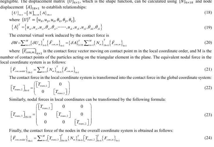
negligible. The displacement matrix {𝑈}6×1, which is the shape function, can be calculated using [𝑁]6×18 and node displacement {𝐴}18×1 to establish relationships:
U 6 1 =
N 6 18
A18 1 (18)where {𝑈}𝑇= {𝑢
𝑥, 𝑢𝑦, 𝑢𝑧, 𝜃𝑥, 𝜃𝑦, 𝜃𝑧},
A
T=
u u u
xi,
yi,
zi,
xi,
zi,
,
u
xk,
u
yk,
u
zk,
xki,
zk
(19)The external virtual work induced by the contact force is
,
1 18
,
1 1 6 6 1 1 18 6 6 1 = M m T con m T M m T con m m m W U F A N F = = =
(20)where {𝐹⃗⃗⃗⃗⃗⃗⃗⃗⃗⃗⃗ }𝑐𝑜𝑛,𝑚 6×1 is the contact force vector moving on contact point m in the local coordinate order, and M is the number of contact points of the particles acting on the triangular element in the plane. The equivalent nodal force in the local coordinate system is as follows:
,
18 1 =
=1
18 6
,
6 1T M
con nodal m m con m
F N F (21) The contact force in the local coordinate system is transformed into the contact force in the global coordinate system:
,1 ,2 6 6 ,1 0 0 trans trans trans T T T = (22) Similarly, nodal forces in local coordinates can be transformed by the following formula:
,2 ,3 18 18 ,2 ,2 0 0 0 0 0 0 trans trans trans trans T T T T = (23) Finally, the contact force of the nodes in the overall coordinate system is obtained as follows:
,
18 1 =
=1 ,318 18
18 6 ,26 6
,
6 1T T
M T
con nodal m trans m trans com m
F T N T F (24)
4. Effect of Particle Restitution Coefficient
The restitution coefficient reflects the elastic deformation in the collision process and is related only to the collision object’s material. It is defined as the ratio of the average relative separation velocity to the normal relative approach velocity of the contact points of two objects before and after the collision. Therefore, according to this definition, the values of the restitution coefficient in two particular scenarios can be obtained: for elastic collision, the restitution coefficient is 1; for entirely inelastic collision, the restitution coefficient is 0.
The modal information of the gear is obtained by finite element analysis of the driven gear with damper. The first three modes are shown in Fig. 4 and the natural frequency of the gear is shown in Table 3. In the gear transmission, the input is the motor speed, and the excitation speed is a fixed value, so the excitation frequency is a fixed frequency. From the above modal analysis results, it can be seen that the natural frequency of the gear is far greater than the excitation frequency. In order to ensure that the excitation frequency will not cause gear resonance and affect the transmission of the gear system, this paper does a fixed frequency analysis of the gear vibration response.
Table 3 The natural frequency of the gear
Order First Second Third Fourth Fifth Sixth
Fig. 4. The first three modes of the gear
According to research, the higher the restitution coefficient of particles, the faster the recovery deformation of particles after an inelastic collision, and the faster the rebound speed of the particles. Therefore, the shorter the period of disagreement between particles and between particles and the damper wall, the higher the collision rate, resulting in greater energy consumption. However, the higher the restitution coefficient of the particle surface, the frequently the particle movement attains saturation, the higher the collision force and frequency, and the lower the friction energy consumption between particles. Generally, energy consumption decreases.
Therefore, six restitution coefficients were set in the simulation experiments of this study to obtain the optimal solution. To set the control group experiment, we set the particle size, friction coefficient, and other parameters as constant in the simulation.
Fig. 5. Acceleration response of different particle restitution coefficients at low rotation speeds.
Fig.6 Acceleration spectra of different particle restitution coefficients at low rotation speeds. We selected six types of experimental materials: iron, lead, silicone, rubber, acrylic, and stainless steel.
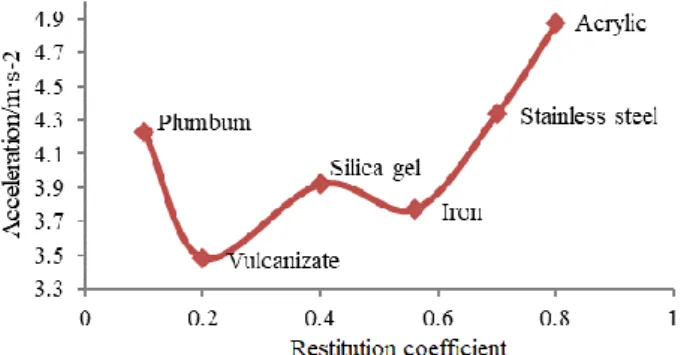
In the low-speed simulation, we sorted the total practical values of acceleration obtained by simulation according to restitution coefficients and compared and screened them with the restorer system values between particles and various materials obtained using the method of shooting balls with high-speed cameras. Figure 6 indicates that the best vibration reduction effect was achieved at a restitution coefficient of approximately 0.2 at low rotation speeds. After adding particles with different restitution coefficients, the acceleration response of the gear decreased significantly, which proved
© 2021 The Japan Society of Mechanical Engineers [DOI: 10.1299/jamdsm.2021jamdsm0033]
that the addition of particle damping has a good damping effect.
Considering a damping effect from 20 to 30 Hz,the vulcanised rubber with a restitution coefficient of 0.2 had the lowest acceleration at low rotating speeds. When the restitution coefficient is about 0.7, the damping effect was the best at a high speed, and the material was stainless steel, which was different from the conclusion obtained at a low speed.
Fig.7 Acceleration response of different particle restitution coefficients at various speeds. In this study, three rotational speeds were set at 400, 800 and 1200 rpm.
5. Experimental Verification of Gear Transmission System
In the particle damping test, the effect of the particle restitution coefficient on the vibration reduction effect of a gearbox at different rotating speeds was studied. Experiment equipments are composed of the gear test rig, a data acquisition and analysis software from COINV Co., and CA-YD-3193 acceleration sensor from SINOCERA PIEZOTRONICS.INC. (Figure 8). The main control board controlled the test gearbox. The speed sensor was installed on the gear housing to measure the vibration of the gearbox. The particle damper was installed in the gear lightening hole. In order to measure the vibration of the gear device, an acceleration sensor was installed on the output shaft of the test device. Through the sensor signal measurement, it was sent to the data acquisition instrument. The test results were displayed by computer analysis software.
Fig.8 Test system. The main control board controlled the test gearbox. The speed sensor was installed on the gear housing to measure the vibration of the gearbox. The particle damper was installed in the gear lightening hole.
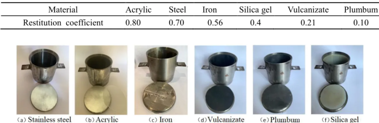
In this study, we changed the surface restitution coefficient by changing the material of the inner surface of the damper. Through calculation, the different restitution coefficients between the particles and the wall of the damper corresponding to the dampers of different inner wall materials were obtained. The restitution coefficient of each group is shown in Table 4.The filling rate of stainless steel particles with a diameter of 8mm in the damper is 90%. The dampers
and their restitution coefficients are shown in Figure 9.
Table 4 The restitution coefficient of different material
Material Acrylic Steel Iron Silica gel Vulcanizate Plumbum
Restitution coefficient 0.80 0.70 0.56 0.4 0.21 0.10
Fig.9 Dampers and their restitution coefficients. We used vulcanized rubber, silica gel, lead, iron, acrylic, stainless steel, and other materials such as paste layer to adhere the material to the damper’s inner surface. The restitution coefficient between the particles and the wall of the damper was changed by changing the materials attached to the inner wall of the dampers. The vibration acceleration of gears at different speeds and restitution coefficients is shown in Figure 10.
Fig.10Spectrum of the test. Figure shows the vibration acceleration of gears at different speeds and restitution coefficients.
Fig.11 Comparison of the test and simulation. The vibration reduction effects of different recovery coefficients at different rotational speeds are different.
The vibration response of the gearbox without damper was tested at different speeds. The vibration test was carried out again after adding the particle damper. Compared with the corresponding test data, the vibration characteristics of the gearbox before and after adding the damper were obtained. By comparing the experimental data with the simulation data, the correctness of the theoretical calculation was analyzed.
© 2021 The Japan Society of Mechanical Engineers [DOI: 10.1299/jamdsm.2021jamdsm0033]
At low rotating speeds, at a restitution coefficient of 0.2, the vibration reduction effect was the best. As the restitution coefficient increased, the vibration reduction effect of the damping particles on the gearbox improved within a specific range. The best vibration reduction occurred at the particle restitution coefficient of approximately 0.7. When the restitution coefficient of the particles was increased further, the damping effect of the damping particles worsened. The restitution coefficient primarily affected the energy consumption of the particles in the collision. The restitution coefficient was small and the rebound speed of particles was low, but the number of collisions per unit time decreased. However, when the restitution coefficient of particles was significant, the particles gradually changed from inelastic to elastic collision; thus, the energy dissipation value of particles decreased after a single collision, and the damping effect decreased. After adding particles with different restitution coefficients, the acceleration response of the gear decreased significantly, proving that the addition of particle damping has a good damping effect.
6. Conclusion
In this study, the discrete element method was used to establish a dynamic model of a gear transmission system. A simulation was conducted by configuring particle dampers in the gear to dissipate the energy in the gear transmission, and a gear transmission test bench was constructed. By employing theoretical analysis and experimental verification, we studied the performance of the damper under different gear transmission conditions, the effect of the restitution coefficient on the damping effect, and the effect rule of the particle restitution coefficient on vibration suppression. Through experimental verification, we determined the optimum restitution coefficient under various operating conditions of the gear. The conclusions of this study are as follows:
(1) The effect rule of the particle restitution coefficient on the damping effect of gear transmission was obtained through a discrete element simulation. When particles with different restitution coefficients were added to the system, the acceleration response of the gear decreased significantly, proving that the addition of particle damping has a good damping effect. Therefore, for gear transmissions under different operating conditions, the inner wall material of the damper corresponding to the restitution coefficient with the best damping effect can be selected. This is significant for vibration and noise reduction in gear transmission systems.
(2) When other parameters, such as particle size, filling rate, and friction coefficient are given absolute values, the best vibration effect can be obtained when the restitution coefficient is approximately 0.2 and the gear speed is low; at relatively high speeds, the damping effect is better when the restitution coefficient is approximately 0.7.
(3) The simulation results of the effect of the restitution coefficient on the damping effect of gear transmission were consistent with the experimental results: When the gear speed is relatively low, the particle damping effect is the best at the restitution coefficient is 0.2, while at higher gear speeds, the particle damping effect is better when the restitution coefficient is approximately 0.7.
Acknowledgements
This work was supported by the National Natural Science Foundation of China [No.51875490]; Aeronautical Power Foundation of China [No. 6141B09050346]; Guangdong Basic and Applied Basic Research Foundation [No.2020A1515010843]; Fundamental Research Funds for the Central Universities (CN) [No.20720180063]; and Science and Technology Program of Xiamen Construction Bureau [No.XJK2019-1-8].
References
Ambarisha, V.K. and R.G. Parker, Nonlinear dynamics of planetary gears using analytical and finite element models. Journal of Sound and Vibration, Vol.302, No.3(2007), pp. 577-595.
Bai, X.M., et al., Investigation of particle damping mechanism via particle dynamics simulations. Granular Matter, Vol. 11, No.6(2009), pp. 417-429.
Bonori G, Barbieri M, Pellicano F. Optimum profile modifications of spur gears by means of genetic algorithms. Journal of Sound and Vibration, Vol. 313, No.3-5(2008), pp. 603-616.
Burns, S.J. and K.J. Hanley, Establishing stable time-steps for DEM simulations of non-collinear planar collisions with linear contact laws. International Journal for Numerical Methods in Engineering, Vol. 110, No.2(2017), pp.
186-200.
Chen, S.Y., et al., Effect of Modification on Dynamic Characteristics of Gear Transmissions System. Journal of Mechanical Engineering, Vol. 50, No.13(2014), pp. 59-65 (in Chinese).
Chen, Z.G. and Y.M. Shao, Dynamic simulation of spur gear with tooth root crack propagating along tooth width and crack depth. Engineering Failure Analysis, Vol. 18, No.8(2011), pp. 2149-2164.
Chen, Z.G. and Y.M. Shao, Mesh stiffness calculation of a spur gear pair with tooth profile modification and tooth root crack. Mechanism and Machine Theory, Vol. 62, No.8(2013), pp. 63-74.
Desrues, J., et al., From discrete to continuum modelling of boundary value problems in geomechanics: An integrated FEM-DEM approach. International Journal for Numerical and Analytical Methods in Geomechanics, Vol. 43, No.5(2019), pp. 919-955.
Dion J.L.,Moyne S.L.,Chevallier G. Gear impacts and idle gear noise: Experimental study and non-linear dynamic model. Mechanical Systems and Signal Processing, Vol. 23, No.8(2009), pp. 2608–2628.
Di Renzo, A. and F.P. Di Maio, Comparison of contact-force models for the simulation of collisions in DEM-based granular flow codes. Chemical Engineering Science, Vol. 59, No.3(2004), pp. 525-541.
Dogruer. C.U., Pirsoltan A. K., Active vibration control of a single-stage spur gearbox. Mechanical Systems and Signal Processing, Vol. 85, (2017), pp. 429-444.
Hu, Y.M., J.K. Fan, and J. Yu, Study of the Influences of Transient Crack Propagation in a Pinion on Time-Varying Mesh Stiffness(2016), pp. 37-37(1) , Shock and Vibration.
Kruggel-Emden, H., et al., A study on the validity of the multi-sphere Discrete Element Method. Powder Technology, Vol. 188, No.2(2008), pp. 153-165.
Kuo, H.P., et al., The influence of DEM simulation parameters on the particle behaviour in a V-mixer. Chemical Engineering Science, Vol. 57, No.17(2002), pp. 3621-3638.
Li, Y.N., et al., Method and experiment study for active vibration control of gear meshing. Journal of Vibration Engineering, Vol. 27, No.2(2014), pp. 215-221(in Chinese).
Ma, H., et al., Review on dynamics of cracked gear systems. Engineering Failure Analysis, Vol. 55, (2014), pp. 215-221. Mao, K.M., et al., DEM simulation of particle damping. Powder Technology, Vol. 142, No.2-3(2004), pp. 154-165. Onate, E. and J. Rojek, Combination of discrete element and finite element methods for dynamic analysis of
geomechanics prob-lems. Computer Methods in Applied Mechanics and Engineering, Vol. 193, No. 27-29 (2004), pp. 3087-3128.
Panossian, H.V., STRUCTURAL DAMPING ENHANCEMENT VIA NONOBSTRUCTIVE PARTICLE DAMPING TECHNIQUE. Journal of Vibration and Acoustics-Transactions of the Asme, Vol. 114, No. 1 (1992), pp. 101-105. Parey, A., et al., Dynamic modelling of spur gear pair and application of empirical mode decomposition-based statistical
analysis for early detection of localized tooth defect. Journal of Sound and Vibration, Vol. 294, No. 3 (2006), pp. 547-561.
Peng, N, et al., Study on the Influence of Type C Damping Ring Structure Parameter on Dynamics Characteristic of Bevel Gear Transmission. Journal of Mechanical Transmission, Vol. 38, No. 8 (2014), pp. 1-5 (in Chinese).
Rougier, E., A. Munjiza, and N.W.A. John, Numerical comparison of some explicit time integration schemes used in DEM, FEM/DEM and molecular dynamics. International Journal for Numerical Methods in Engineering, Vol. 61, No. 6 (2004), pp. 856-879.
Tuttle, T.D. and W.P. Seering, A nonlinear model of a harmonic drive gear transmission. Ieee Transactions on Robotics and Au-tomation, Vol. 12, No. 3 (1996), pp. 368-374.
Wang, P., Su, Z.T., Wang, S., et al., Research progress of graphene/rubber composite materials at home and abroad. Advanced Materials Industry, No. 6 (2015), pp. 58-66 (in Chinese).
Xiao, W.Q., et al., Effect of powder material on vibration reduction of gear system in centrifugal field. Powder Technology, Vol. 294, (2016), pp. 146-158.
Xu, Z.W., M.Y. Wang, and T.N. Chen, Particle damping for passive vibration suppression: numerical modelling and experimental investigation. Journal of Sound and Vibration, Vol. 279, No. 3-5 (2005), pp. 1097-1120.