Effect of inertia term on the undrained triaxial compression behavior
Xu, B., Nakai, K., Noda, T., Kishimoto, M., (Nagoya University) Takaine, T., (Asanuma Corporation)
Effect of inertia term on the undrained triaxial compression behavior
triaxial compression test, rate of loading, effective stress analysis Nagoya University ○Binbin Xu (Student) Nagoya University Kentaro Nakai (International) Nagoya University Toshihiro Noda (International) Nagoya University Masahiro Kishimoto (Student) Asanuma Co., LTD Toshihiro Takaine (Regular) 1. Introduction
A three dimensional analysis for triaxial compression test will be presented in the paper. Loading controlled by strain under various velocities is performed to seek the influence of the inertia term and migration of pore water inside the specimen. Soil-water coupled FEM code, named GEOASIA1), 2), 3) that can deal with static and dynamic behaviors, is employed to state clearly the inertia effect on the saturated specimen. The jerk term that is the derivative of acceleration, together with updated-Lagrange scheme, makes the geometrical nonlinearity including the inertial term possible.
2. Analysis conditions
In the analysis, the soil specimen is a cylinder with a diameter of 3.5cm and a height of 8cm which is modeled with 8-node hexahedral isoparametric elements. The finite element mesh used in the analysis is shown in Fig. 1. It is divided into 441 nodes and 320 elements with 16×3×8 circumferential, radial and vertical directions separately. Two boundary conditions are considered: A) Frictionless ends at the top and bottom surfaces where every node at the top and bottom are assumed with roller condition, B) Frictional ends that horizontal movement is restrained at both top and bottom ends, which is similar to the ordinary triaxial test. Loading is controlled by the displacement (axial strain) and equivalent velocity v is given to all the nodes at the top surface. All the analyses are conducted under
undrained hydraulic condition. Table 1 presents the material constants and initial conditions. Non-structured fully remolded clay was considered in this analysis.
3. Undrained compression tests with frictionless ends
To emphasis the significance of inertia term, comparison between the distributed velocity on every layer and the extremely rapid velocity on the top surface under frictionless ends is conducted. As for the distributed velocity, it means that a group of linear decreasing velocities is imposed vertically with a maximum of 0.0001cm/s on the top to eliminate the inertial effect, as shown in Fig. 2. On the other hand, as for top layer loaded, constant rates are exerted only on the top at 103cm/s monotonically. Fig.3 shows the distributions of shear strain
s. Fig.3 (a) gives the undeformed configuration of both specimen and Fig.3 (b)(c) show the distributed loading and the top loaded when the 20% axial strain arrives. Compared with Fig.3 (b) and Fig.2 (c), atotally uniform deformation that acts as a single element can be observed in the former, while the shear strain concentrates at the upper side and expands circumferentially and the asymmetry deformation along the height results from the vertical and lateral inertial forces.
4. Undrained compression tests with frictional ends
Undrained triaxial compression tests on condition of various strain rates for frictional ends are analyzed. Three different strain rates, 1.0×10⁻⁵cm/s, 1.0×101cm/s and
3.5cm 8.0cm
Fig. 1 Finite element mesh Fig. 2 Finite element mesh
0%
50%
(a) undeformed (b) distributed (c) 1000cm/s at the top
Fig.3 Shear strain distributions with different loading manner
Table 1 Material constants and initial conditionsElasto-plastic parameters
Critical state index M 1.55 NCL intercept N 2.00 Compression index ~
0.108 Swelling indes ~ 0.025 Poisson’s ratio 0.30 Soil particle density s(g/cm3) 2.65 Mass permeability index k(cm/s) 2.0×10⁻⁸
Initial conditions
specific volume v0 1.88 stress ratio 0 0.0 degree of structure 1/R*0 1.0 degree of Overconsolidation 1/R0 1.0 degree of anisotropy 0 0.0
1.0×103cm/s are imposed at the top to investigate the deformation pattern and migration of pore water. Fig. 4, 5 and 6 present the shear strain distribution at different stages respectively. If the loading speed is very large, like v=103cm/s (Fig. 6), the shear strain concentrated and larger at the top surface. As described in 3., the inertial term plays a crucial role and deformation concentrates on top part of specimen. While, if the loading speed is slow to some extent (Fig.4 and 5), the shear strain becomes large at the central part of specimen and seems almost same deformation that continue to keep axial symmetry deformation despite different loading speeds. It can be attributed to the effect of robust restriction on two ends.
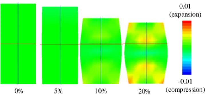
Fig. 7 and 8 show the specific volume change distribution on the cross-section intercepted at the center of specimen. The slow loading permits the pore water flowing freely inside the specimen and significant migration of pore water. Therefore, Fig.7 presents compression and expansion at the same time by location. On the other hand, Fig. 8 which loading speed is rapid, specific volume is almost constant at every place. The larger the loading velocity is, the less evident the specific volume change is inside the sample. Although the boundary is impermeable, the delivery of the pore water between the elements can be observed due to the migration of pore water.
5. Conclusions and Future challenges
Utilizing the 3D analysis, the following conclusions are obtained: 1) when the strain rate is extremely rapid, the asymmetric deformation along the height is significant due to the inertia term; 2) Migration of pore water inside the specimen becomes neglectable as the loading velocity increases and the compression accompanying with expansion occurs in spite of undrained boundary. 3) Constrained by the friction in experimental, the shear behavior that concentrated in the middle has no great relation to the inertia term and migration of pore water.
The concentrated shear behavior obviously cannot represent the experimental results. The initial axial symmetry and the following symmetry restrained by the great constrains contribute a lot to such a result. Therefore, more realistic friction in rough pedestal and remove of axial symmetry by introducing initial imperfection will be the main orientation in the future.
Reference
1) Asaoka, A. et al. (1994): Soil-water coupled behavior of saturated clay near/at critical state, S&F, 34(1): 91-105. 2) Noda, T. et al. (2008): Soil-water coupled finite deformation analysis based on a rate-type equation of motion incorporating …, S&F, 48(6), 771-790. 3) Asaoka, A. et al. (2002): An elasto-plastic description of two distinct volume change mechanisms of soils, S & F, 42(5): 47-57.
0% 5% 10% 20% 0%
50%
Fig. 4 Shear strain distributions under v=10-5cm/s
0% 5% 10% 20% 0%
50%
Fig. 5 Shear strain distributions under v=10cm/s
0% 5% 10% 20% 0%
50%
Fig. 6 Shear strain distributions under v=103cm/s
0% 5% 10% 20%
-0.01 (comperssion)
0.01 (expansion)
Fig. 7 Specific volume change distributions under v=10-5cm/s
0% 5% 10% 20%
-0.01 (compression)
0.01 (expansion)
Fig. 8 Specific volume change distributions under v=10cm/s