日本機械学会 2012 年度年次大会 [2012.9.9‐12]
CopyrightⒸ2012 一般社団法人 日本機械学会
[No.12-1] 日本機械学会 2012 年度年次大会講演論文集 〔2012.9.9‐12,金沢〕
J045033
エンリッチ有限要素法による 3 材料接合体の特異性の強さの解析
*(寸法と材料特性の影響)
Analysis of intensity of singularity for three-material joints using an enriched finite element method
(Discussion on an influence of the geometry and material properties) Chonlada LUANGARPA
*1and Hideo KOGUCHI
*2*1
Graduate school of Nagaoka University of Technology 1603-1 Kamitomioka, Niigata
*2
Nagaoka University of Technology 1603-1 Kamitomioka, Niigata
In this study, the enriched finite element method is applied to compute intensity of singularity for three-material joints with 2-real singularities. The models with different material combination and different geometry are investigated to study the influence of material properties and geometries on the singular stress field. In conclusion, it is shown that the enriched finite element method can be used to determine the singular stress fields for 2-real singularities. The intensities of singularity increase with increasing of lengths. Finally, the results for various Young’s modulus of material 3 show that the 1
stintensity of singularity, K
θθ1, increases when the stiffer material was used in material 3, but the 2
ndintensity of singularity, K
θθ2, decreases.
Key Words : Stress singularity, Enriched finite element method, Intensity of singularity
1. Introduction
Dissimilar material joints have singularities created by discontinuities in material properties across an interface. For this reason, it is difficult to predict an accurate stress by using conventional FEM. There are some special elements or methods developed for solving this problem. An enriched finite element method developed by Benzley
(1)is one method that can directly compute the intensity of singularity and do not need to divide into very small meshes around the singular point.
In the present study, the singular stress field in three-material joints is analyzed by the enriched finite element method. In order to improve an accuracy of the results, the method is modified by changing a mesh type from 4-node to 8-node elements and the appropriate element size and enriched region are discussed. An eigenvalue and eigenvector analysis is applied to calculate the order of stress singularities and the asymptotic displacement fields on the enriched elements. The joint models with various lengths and different material combination are investigated to study the influence of material properties and geometries on the singular stress field.
2. Analytical formula
Stress distribution around the singular point with two real singularities can be described as
!
ij= K
1r
!"1f
ij1(#) + K
2r
!"2f
ij2(# )
(1)where r is the radial distance from the singular point, λ
k, K
kand f
ijk( θ ); (k = 1,2), are the orders of the stress singularity, intensities of singularity and angular functions, respectively.
*1 正員,長岡技術科学大学大学院(〒940-2188 長岡市上富岡町 1603-1)
E-mail: [email protected] *2 正員,長岡技術科学大学 工学部
2D enriched element equations were developed by Benzley
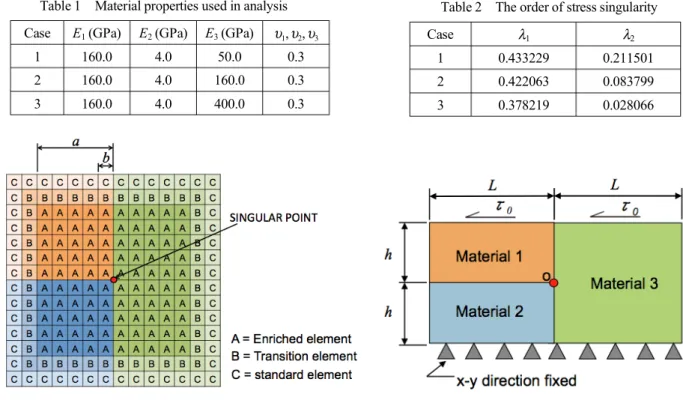
(1)to determine an intensity in stress and displacement for a crack. In this method, 3 types of element; enriched, transition and standard elements, are used. (See Fig. 1)
The displacement in an enriched element (type A element) is assumed as the form
u
k= g
nn=1
!
mu
kn+ K
!!1(Q
k1" g
nn=1
!
mQ
kn1) + K
!!2(Q
k2" g
nn=1
!
mQ
kn2)
(2)In eq.(2), u
1and u
2represent the displacements of a point within the element in the x- and y- directions, respectively. Q
k1and Q
k2are the intensities of singular terms (unknown coefficients) for λ
1and λ
2, respectively. u
kn, Q
kn1and Q
kn2are the values of u
k, Q
k1(r,!) and Q
k2(r,!) evaluated at node n, m is the number of node in an element and g
nis the standard finite element shape function.
For transition elements (type B element), they are needed to join enriched elements to standard elements in a finite element model. The displacement field in a transition element is given by the relation
u
k= g
nn=1
!
mu
kn+ R(!,"){K
##1(Q
k1" g
nn=1
!
mQ
kn1) + K
##2(Q
k2" g
nn=1
!
mQ
kn2)}
(3)where R( ξ , η ) is set a ‘zeroing’ function, equals 1 along ‘enrich’ boundaries and equals 0 along ‘standard’ boundaries.
For finding the asymptotic displacement fields on the enriched element, an eigenvalue analysis by FEM is used separately.
By using eigen analysis method, the order of the stress singularity, λ
, and the angular variation of the displacement fields canbe determined in polar coordinates (u
r, u
θ). Then, the function Q
i(i=1, 2) converted from polar coordinates to Cartesian coordinates may be written as
Q
1= r
1!!(u
r(")cos(" ) ! u
"(" )sin(" )) / E
1Q
2= r
1!!(u
r(" )sin(" ) + u
"(" )cos(")) / E
1 (4)where E
1is Young’s modulus of material 1 and θ is an angle from x-axis.
3. Numerical analysis 3・1 Model for analysis
The model for analysis is the three-material joint model fixed on the bottom side and applied shear loading ( τ
0= 1 MPa) on the top surface, as shown in Fig. 2. Plane strain condition is considered. In order to study a relationship between the intensity of singularity and model’s size, the models that fixed its thickness (h = 10 mm) and varied its length (L) from 60 to 300 mm are analyzed.
In addition, three cases of different material combination are chosen to study an influence of material properties on the intensities of singularity. Properties of material 1 and material 2 are fixed, and only Young’s modulus of material 3 is varied from 50, 160 and 400 GPa. (See Table 1)
3・2 Eigenvalue analysis
Eigenvalue analysis by FEM (Pageau and Biggers
(2)) is used to find displacement fields in the enriched element. The eigen equation can be expressed as:
(5)
where [A], [B] and [C] are matrices composed of Young’s modulus and Poisson’s ratio, p = 1- λ and {u} is the eigenvector of displacement.
(p2[A]+p[B]+[C]){u}=0
Fig. 1 Element models for Enriched Analysis Fig. 2 Analytical model and boundary condition
The orders of stress singularity, λ , determined from eigenvalue analysis are presented in Table 2. The results show that all 3 cases are two-real singularities, and the orders of stress singularity decrease with increasing of Young’s modulus of material 3, E
3. The angular variation of displacement is analyzed by eigenvector analysis and converted to angular functions followed stress-strain relationship. The angular functions, f
θθ1and f
θθ2, are shown in Figs. 3 and 4, respectively. f
θθ1for three cases are similar to each other, the angle for maximum stress is about 40-50º or inside of material 3, while the angle for maximum stress of f
θθ2is inside the material with the largest Young’s modulus.
3・3 Enriched FEM
The element model for enriched FEM analysis is shown in Fig. 1. The model with enriched element size, b, = 0.1 mm and the enriched region size, a, of 0.5x0.5 mm
2are employed. The intensities of singularity, K
θθ1and K
θθ2, with various lengths (L
= 60 - 300 mm) for fixed thickness (h = 10 mm) are shown in Figs. 5 and 6, respectively. These results show that the intensities of singularity, both K
θθ1and K
θθ2, gradually increase with increasing of lengths, L. In addition, the effect of the ratio of Young’s modulus of material 3, E
3, on the intensities of singularity shows that the 1
stintensity of singularity, K
θθ1, increases with increasing of E
3, but the 2
ndintensity of singularity, K
θθ2, decreases.
4. Conclusions
The enriched FEM was developed for calculating the intensity of singularity of two-real singularities. The results for various model lengths show that the intensities of singularity increase with increasing of lengths. Finally, the results for various Young’s modulus of material 3 show that K
θθ1increases when the stiffer material was used in material 3, while K
θθ2decreases.
References
(1) Benzley, S.E., “Representation of Singularities with Isoparametric Finite Elements”, Int.J.Numerical Methods in Engineering, Vol. 8, No. 3 (1974), pp. 537-545.
(2) Pageau S.S., Bigger S.B., “Enrichment of Finite Elements with Numerical Solutions for Singular Stress Fields”, Int.J.Numerical Methods in Engineering, Vol. 40, No. 14 (1997), pp. 2693-2713.
Case
λ1 λ21 0.433229 0.211501
2 0.422063 0.083799
3 0.378219 0.028066
Table 2 The order of stress singularity Case
E1(GPa)
E2(GPa)
E3(GPa)
υ1, υ2, υ31 160.0 4.0 50.0 0.3
2 160.0 4.0 160.0 0.3
3 160.0 4.0 400.0 0.3
Table 1 Material properties used in analysis
(3) Koguchi, H and Luangarpa, C., “Two-Dimensional Joint Analysis Under Shear Loading Using Enriched Finite Element”, Journal of Solid Mechanics and Materials Engineering, Vol. 2 (2008), pp. 319-332.
Fig. 3 Angular functions, f
θθ1, for λ
1Fig. 4 Angular functions, f
θθ2, for λ
2Fig. 5 The 1st-intensity of singularity, K
θθ1, against L/h Fig. 6 The 2nd-intensity of singularity, K
θθ2, against L/h -1.5
-1.0 -0.5 0.0 0.5 1.0 1.5
f!!1
-180 -90 0 90 180
! degree
E
3= 400 GPa E
3= 160 GPa E
3= 50 GPa
-1.5 -1.0 -0.5 0.0 0.5 1.0 1.5
f!!2
-180 -90 0 90 180
! degree
E
3= 400 GPa E
3= 160 GPa E
3= 50 GPa
10 8 6 4 2 0
K
!!1N .m m
"1#235 30 25 20 15 10 5 0
L/h
E3 = 400 GPa E3 = 160 GPa E3 = 50 GPa
-10 -8 -6 -4 -2 0
K
!!2N .m m
"2#235 30 25 20 15 10 5 0
L/h
E3 = 400 GPa E3 = 160 GPa E3 = 50 GPa