Synchronization Phenomena in Coupled Oscillators Containing Star Structure Connected to Another
Oscillator with Different Coupling Strength
Vu Minh Hien, Minh Hai Tran, Yoko Uwate and Yoshifumi Nishio
Dept. of Electrical and Electronic Engineering, Tokushima University2-1 Minami-Josanjima, Tokushima 770–8506, Japan Email:{hien,minhhai,uwate,nishio}@ee.tokushima-u.ac.jp
Abstract—In this study, synchronization phenomena in coupled oscillators containing star structure connected to another oscil- lator is investigated. We focus on the phase different between two oscillators when coupling strength is changed. Furthermore, we also investigate the effect of the initial condition. By using computer simulations, we observe synchronization phenomena of the system.
I. INTRODUCTION
Synchronization phenomena are observed everywhere in our world. For example, firefly luminescence, birds and frogs crying, human aplause and so on. It has a long history of research and its applications can be widely found in many fields of science, such as chemical, physical, biological, and also social systems. Therefore, investigation of synchroniza- tion phenomena has become an important issue.
The van der Pol oscillator is the symple circuit. It consists of resistor, inductor, capacitor and nonlinear resistor. Syn- chronization phenomena of van der Pol oscillator is the one of nolinear phenomena that can be observed similar natural phenomena by controling frequencies.
Fig. 1. van der Pol oscillator.
In this study, we proposed a new type of coupled van der Pol oscillators system: Star structure connected to another oscillator. By carring out computer simulations, relationship of the model between synchronization phenomena and coupling strength is investigated.
II. CIRCUIT MODEL
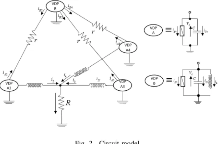
The proposed circuit is shown in Fig. 2. We used three van der Pol oscillator coupled as star structure that connected another oscillator via resistorr. We investigate synchronization phenomena by changing coupling strength of resistorR.
Fig. 2. Circuit model.
The circuit equations of VDP-B are given as folows:
−ig1−ic1−iL1=iB2+iB3+iB4 LdiL1
dt =v1
v1−v2=r(iB2−iA2) v1−v3=r(iB3−iA3) v1−v4=r(iB4−iA4),
(1)
where v1 denote the voltage of oscillator VDP-B.
The circuit equations of VDP-A are given as follows:
−igk−ick=iAk+ik
vk−vLk=R
∑4 n=2
iLn. (2)
(k= 2,3,4) Nonlinear resistor defined as follows:
ign=−g1vn+g3vn3. (3)
- 69 -
IEEE Workshop on Nonlinear Circuit Networks December 15-16, 2017
By changing the variables and parameter:
t=√
LCτ, vn=
√g1 3g3
xn, in=
√ g1C
3g3Lyn, α=g1
√L C, β= 1
r
√L C, γ=R
√C L.
(4)
The normalized circuit equation of VDP-B are given as follows:
dx1
dτ =α(x1−1
3x31)−y1+β(3x1−
∑4 n=2
xn) dy1
dτ =x1.
(5)
The normalizaed circuit equation of VDP-A are given as follows:
dxn
dτ =α(xn−1
3x3n)−yn−β(x1−xn) dyn
dτ =xn−γ
∑4 n=2
yn,
(6)
where parameters α, β, γ denote the coupling strengh of the inductor, resistorsrand resistorR.
III. SYNCHRONIZATIONPHENOMENA
For the computer simulations, we calculates Eqs.(2)-(5) by using the Runge-Kutta method with the step size h = 0.05.
We show the simulation results when the parameters of the circuit model are fixed asα= 0.01,β= 0.01andγ= 0.007.
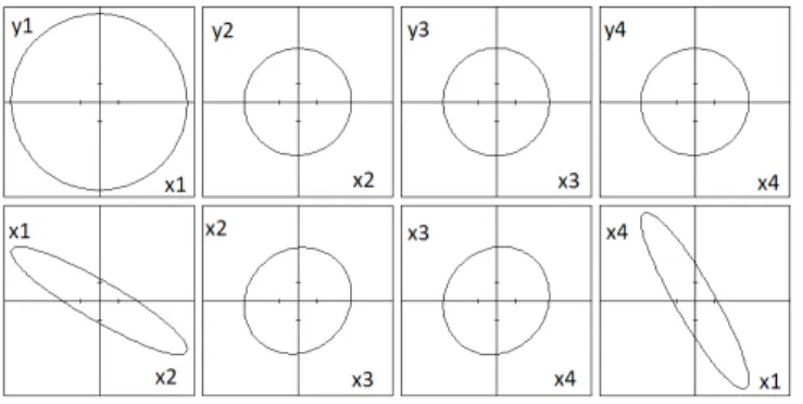
Figure 3 shows the attractor of each oscillator with the horizontal axis is the voltage and the vertical axis is the electric current of each oscillator.
First, we investigate the effect of different the initial con- dition. As simulation results are shown in Fig. 4, we obtain that, by changing initial values, 2 oscillators of VDP-A can become in-phase.
Fig. 3. Attractor between adjacent oscillators (α= 0.01,β= 0.01,γ = 0.007).
Fig. 4. Phase difference (α= 0.01,β= 0.01,γ= 0.007).
Next, we decrease the values of parameterγfrom 0.007 to 0.005 and continue conducting computer simulation. In this case, all four oscillatos become synchronization with second, third and fourth oscillator of VDP-A are in-phase and only first oscillator of VDP-B is anti-phase. The result of simulation is shown in Fig. 5.
Fig. 5. Phase difference (α= 0.01,β= 0.01,γ= 0.005).
Figure 6 shows the computer simulation results of the phase difference when parameter γ is changed from 0.001 to 0.009 with step size 0.001. In this case, we can obtain that, when value of parameterγis smaller than 0.005, second, third, fourth oscillator of VDP-A are in-phase and only first oscillator of VDP-B is anti-phase.
Fig. 6. Phase difference (α= 0.01,β= 0.01).
Therefore, we can control synchronization phenomena by changing initial values or the coupling strengths.
- 70 -
IV. CONCLUSIONS
In this study, we have investigated the synchronization phenomena in coupled oscillators containing star structure connected to another oscillator. By computer simulation, we have observed the synchronization phenomena by changing initial values and coupling strength. In the case of chaging initial values, in three oscillators of VDP-A, two oscillators can become in-phase. By decreasing coupling strength, all four oscillators can become synchronization with oscillators of VDP-A are in-phase and only oscillator of VDP-B is anti- phase.
In the future, we experiment the proposed circuit model.
REFERENCES
[1] K. Ueta, Y. Uwate and Y. Nishio, “Synchronization Phenomena in Complex Networks of van der Pol Oscillators,” Proceedings of RISP International Workshop on Nonlinear Circuits, Communications and Signal Processing (NCSP’17), pp. 285-288, Mar. 2017.
[2] Y. Uwate, Y. Nishio and R. Stoop, “Synchronization in Three Coupled van der Pol Oscillators with Different Coupling Strength,” Proceedings of RISP Inernational Workshop on Nonlinear Circuits, Communications and Signal Processing (NCSP’10), pp. 109-112, Mar. 2010.
[3] V. Thuan, Y. Uwate and Y. Nishio , “Synchronization Phenomena in van der Pol Oscillators with Different Amplitudees,” Proceeding of International Symposium on Nonlinear Theory and its Applications NOLTA’14, Luzern, Switzerland, Sep. 2014.
[4] K. Matsumura, T. Nagai and Y. Nishio, “Analysis of Synchronization Phenomena in Coupled Oscillator Chains” Proceedings of IEEE Inter- national Symposium on Circuits and Systems (ISCAS’12), pp. 620-623, May. 2012.