SUMMARY We propose multi-core erbium-doped fiber amplifiers for next-generation optical amplifiers utilized by space-division multiplex- ing technologies. Multi-core erbium-doped fiber amplifiers were studied widely as a means for overcoming exponential growth of internet traffic in the backbone network. We consider two approaches to excitation of er- bium irons; One is core-pumping scheme, the other is cladding-pumping scheme. For a core-pumping configuration, we evaluate its applicability to future ultra long-haul network. In addition, we demonstrate that cladding- pumping configuration will enable reduction of power consumption, size, and cost because one multimode pumping laser diode can excite several cores simultaneously embedded in a common cladding and amplify several signals passed through the multi-core erbium-doped fiber cores.
key words: multi-core EDFA, cladding pumping, low power consumption
1. Introduction
Space division multiplexing (SDM) in optical fiber has at- tracted interest recently due to its potential use in enhanc- ing the capacity of transmission systems [1]–[3]. Optical signals from different channels can be multiplexed in the space domain using multiple cores embedded in the com- mon cladding of a fiber [4]–[6], or using various transverse modes of multi-mode fibers [7], [8]. Multi-core fiber (MCF) based on space division multiplexing have recently been fabricated and demonstrated to increase the capacity limit in one fiber of 100 Tbit/s for overcoming exponential growth of internet traffic in the backbone network. Using such MCFs, various transmission experiments have been demonstrated with record capacity beyond 100 Tbit/s per one fiber, how- ever, it has been demonstrated with the transmission length of several tenth of kilometers or one transmission span [9].
One of the remaining key milestones to the realization of optical repeatered transmission systems based on MCF, is the introduction of multi-core erbium-doped fiber ampli- fier (MC-EDFA) [10], [11]. A excitation of erbium-doped region in MC-EDF is performed by one of two methods;
one is core-pumping scheme, the other is cladding-pumping scheme. Core-pumping technology is to launch signal and pump light together into MC-EDF cores embedded in a common cladding and to pump each of the cores by sep- arate pumping laser diode. In contrast, cladding-pumping technology is to launch signal light into MC-EDF cores and pump light into the silica cladding of double-cladding struc-
Manuscript received November 11, 2013.
Manuscript revised February 24, 2014.
†The authors are with Fitel Photonics Laboratory, Furukawa Electric Co., Ltd., Ichihara-shi, 290-8555 Japan.
a) E-mail: [email protected] DOI: 10.1587/transcom.E97.B.1265
tured MC-EDF [12], [13]. Recently, it was reported that the transmission experiment with the combination of 7-core MCF and 7-core MC-EDFA with core-pumping was suc- cessfully obtained and the capacity-distance product of 1.03 Exabit/s·km per fiber was achieved [2]. This consideration indicated a MC-EDFA is feasible by core-pumping scheme using conventional EDFA technique. However, MC-EDFA utilizing core-pumping scheme offered little benefit for de- creasing the power consumption, reducing the cost, and downsizing, because the number of the pumping laser diode is the same as the core number. On the other hand, in con- trast to core-pumping scheme, the cladding-pumping with double-cladding structured MC-EDF has possibilities of low power consumption, low cost, and downsizing by utilizing high power multi-mode pumping laser diode with tens of watts, which is much cheaper than single-mode pumping laser diode, because one multi-mode pumping laser diode can excite several cores simultaneously embedded in a com- mon cladding and amplify several signals passed through the MC-EDF cores.
In this paper, we first explain core-pumped MC-EDFA with three cores in a common cladding as a means of demonstrating the cross-talk property between amplified signals. The required cross-talk value of MC-EDFA should be lower than the transmission line. In this study, we tar- get the cross-talk value of less than−30 dB in MC-EDFA.
We then demonstrate core-pumped MC-EDFA with seven cores in a common cladding in order to confirm that all seven cores have the ability to have amplification character- istics as competent as the standard single-core core-pumped EDFA. These results with core-pumped MC-EDFA indicate that MC-EDFA with core-pumped scheme is feasible. Fi- nally, after optimizing a multi-mode pump light coupler, we successfully demonstrate all the 7-core amplification of a double-cladding MC-EDF using the developed multi-mode pump light coupler for the inner cladding excitation.
2. Core-Pumped MC-EDFA with Three Cores
We fabricated core-pumped three-core MC-EDFA with low cross-talk properties and demonstrated its amplification properties. Figure 1 shows the cross-section of fabricated MC-EDF with three cores, where the fiber diameter and the erbium-doped core pitch between cores were 100μm and
30μm, respectively. This three-core MC-EDF was fabri-
cated by stack-and-draw method. By precisely choosing the refractive index difference and core diameter, we optimized Copyright c2014 The Institute of Electronics, Information and Communication Engineers
Fig. 2 Experimental setup by evaluating the cross-talk.
the mode-field diameter (MFD) and cutoff wavelength to meet the demand of this amplifier. The average value of MFD, Aeff, and cutoff wavelength for each core was ob- tained as 6.6μm, 35μm2, and 1005 nm, respectively, where the MFD and Aeff were measured at 1580-nm operating wavelength and the cutoffwavelength was measured in 2- meter long samples. The erbium-doped core had an average fiber gain of 11 dB/m at 1550-nm wavelength. From these results, we confirmed that a desirable structure was obtained and the optical properties, namely MFD, Aeff, and cutoff wavelength, were agreed well with a simulation result.
In order to launch the signal and pump light into two cores out of three cores simultaneously, we have developed a spatial coupling system similar to the reference [14]. The experimental setup is shown in Fig. 2 to demonstrate the cross-talk properties, where the coupling loss due to the spa- tial coupling is 1.3 dB at one side. The tunable laser source (TLS) was used for the signal light and the pump light was launched at 1480-nm wavelength for a forward pumping.
In the aim of an evaluation of the cross-talk properties be- tween the signals launched into each core in the case of the excitation with the pump light, we input the signal light of 1550-nm wavelength in core A from the TLS1 and one of 1551-nm wavelength in core B from the TLS2. From the output core A or B, the signal light of 1550- or 1551-nm wavelength is strongly output, respectively. Figure 3 shows the optical spectrum as a function of wavelength, where the pump light of 1480-nm wavelength was launched into both cores. The blue curve corresponds to the result of output core A and the red curve to the result of output core B. Here, the signal power of a TLS is−15 dBm and the pump power is tuned so as to obtain the output signal power of 0 dBm, where the input pump power to the MC-EDF is 15 mW and 12 mW, respectively. By assuming almost no differ- ence in coupling coefficient between 1550- and 1551-nm wavelength, the cross-talk between cores can be obtained as−33 dB by subtracting the power at 1550-nm wavelength
Fig. 3 Optical spectrum as a function of operating wavelength.
Fig. 4 Gain, NF, and cross-talk measured for different cores.
Fig. 5 Experimental setup for data amplification experiment.
from the power at 1551-nm wavelength in blue curve.
Figure 4 shows the gain, noise figure (NF), and cross- talk properties as a function of wavelength. The gain and NF of the MC-EDF were estimated by considering the insertion loss of the isolator and the WDM coupler of 0.5 dB and cou- pling loss due to the spatial coupling of 1.3 dB at one side, and the cross-talk included a cross-talk generated by spatial coupling. Low cross-talk of less than−30 dB was obtained within the wavelength range of 1540 to 1580 nm as shown in Fig. 4. Moreover, as we can see, high gain of 15 dB and low NF of less than 5 dB at 30-nm wavelength range were successfully measured.
Finally, we performed the 10 Gbit/s NRZ data ampli- fication experiment over 12-meter long MC-EDF. The ex- perimental setup is represented in Fig. 5. The dashed box with MC-EDFA is corresponding to the experimental setup bounded by a dashed line in Fig. 2. The signal light mod- ulated by 10 Gbit/s of 1550-nm wavelength was divided in two by 3-dB coupler, and 5-ns delay was given to the core A path against core B path for signal decorrelation. Af- ter amplification, output signal was detected by the receiver through the band-pass filter. Figure 6 represents the BER performance when each input signal of−15 dBm was ampli-
Fig. 6 Measured BER result.
fied to 0 dBm by MC-EDFA. We successfully obtained the power penalty of less than 1 dB in each core at BER of 10−9 and error free data amplification of BER of 10−12 over 12- meter long MC-EDF. Insets show the output eye diagrams for the amplified signals and the one of back-to-back at BER of about 1×10⁻⁸. It was found from the BER performance shown in Fig. 6 that the cross-talk property of MC-EDF is sufficiently low.
3. Core-Pumped 7-Core MC-EDFA with Fiber-Based Fan-In/Out
Figure 7 shows the cross-sectional view of a 7-core MC- EDF, where the fiber diameter and the erbium-doped core pitch between cores were 180μm and 45μm, respectively.
This seven-core MC-EDF was fabricated by stack-and-draw method. The MFD at 1580 nm was estimated to be about
7.3μm. The average cutoffwavelength among 7 cores was
equal to 1050 nm, where the cutoffwavelength is measured in 2-meter long samples. The erbium-doped core has an attenuation coefficient of 3.4 dB/m and small-signal gain of 4.3 dB/m at 1550 nm. Moreover, in order to identify 7 cores individually, a marker made from a fluorine-doped silica rod was introduced and the cores were numbered according to the maker as shown in Fig. 7.
Coupling of light to the individual cores of the MC- EDF was achieved through two small-diameter fiber bundle fan-in/out. The fan-in/out were fabricated by gathering 7 small-diameter fibers into glass capillary, where the glass diameter of small-diameter fiber was equal to the core pitch of 7-core MC-EDF. In order to evaluate the cross-talk prop- erties of fabricated 7-core MC-EDF, we constructed the ex- perimental setup shown in Fig. 8. TLS was used as a sig- nal, which was combined with pump light at 980 nm using WDM couplers. We used a 16-meter long MC-EDF to ob- tain the effective amplification at C-band. In the aim of an evaluation of the cross-talk properties between signals in the different core, we input the signal and pump light in different combinations. In Fig. 9, we input the signal light of 1550-
Fig. 7 Cross section of 7-core MC-EDF.
Fig. 8 Experimental setup.
Fig. 9 Crosstalk result with signal 1.
nm wavelength in core 1 (center core) from the TLS1 with
−15 dBm and measured the output result of core 1. Blue curve was obtained to measure the output result with only pump light corresponding to core 2 (pump 2), green curve was obtained from the output result with all pump light ex- cept the pump 1, and red curve was obtained with only pump 1, where the pump power was about 40 mW and the resolu- tion in optical spectrum analyzer of 0.1 nm. From this result, we revealed that the cross-talk component to the core 1 of the ASE generated by pump 2 to pump 7 was extremely low compared to the ASE level generated by pump 1.
Next, we simultaneously input the signal light of 1550- nm wavelength in core 1 from the TLS1 and that of 1551- nm wavelength in core 2 from the TLS2 with−15 dBm and measured the output result of core 2 as shown in Fig. 10.
By increasing the pump source such as pump 1 to pump 1+3+4+5+6+7, the amplified signal light of 1550 nm is measured at output core 2, however, it was found that the ASE level generated by pump 2 is high enough compared to the cross-talk components. Therefore, the cross-talk be- tween cores with multi-pump source condition could not be
Fig. 10 Cross-talk result with signal 1 and 2.
Fig. 11 Cross-talk dependence on the different pump power.
defined. Figure 11 shows the cross-talk dependence on the different pump power, where the signal light of 1550 nm was input in core 1 and that of 1551 nm input in core 2. The measured results shown in Fig. 11 were obtained at output core 2 and the power of pump 1 kept the constant of 66 mW.
Blue, Cyan, Green, Purple, and Red curves correspond to the pump 2 power of 0 mW, 16 mW, 24 mW, 37 mW, and 62 mW, respectively. In the case of the pump 2 power of 24 mW, the cross-talk component of 1550-nm signal light was observed at output core 2 because of the ASE level gen- erated by pump 2 is low. However, by increasing the pump 2 power more than 37 mW, it was impossible to determine the cross-talk value due to the ASE noise generated by pump 2. As a result, we could obtain the extremely low cross-talk less than−40 dB, which is larger difference than the ASE level because the cross-talk component was hidden behind the ASE level. Because it was impossible to measure the cross-talk due to the ASE light generated by pump source, we estimated the potential cross-talk of 7-core MC-EDF by launching the signal light of 1640-nm operating wavelength, which was a little absorption loss of 1 dB by 16-meter long EDF. Figure 12 shows the cross-talk properties in the MC- EDF measured at 1640 nm. The horizontal axis represents the core in which light was launched and the vertical axis shows the cross-talk in the signal, where the cross-talk can be considered by measuring the difference in attenuation be- tween corresponding and different cores. It revealed that the potential cross-talk of 16-meter long 7-core MC-EDF is less than−40 dB at all cores. Next, Fig. 13 shows the gain and
Fig. 12 Measured crosstalk at 1640 nm.
Fig. 13 Gain and noise figure.
NF as a function of wavelength. The gain and NF of the MC-EDF were estimated by considering the insertion loss of the WDM coupler, isolator, and fan-in/out. The solid curves correspond to the gain and dashed curves to the NF. The col- ors denoted the corresponding output cores. As we can see, high gain of about 20 dB and low NF of less than 7 dB at the measured wavelength range were obtained.
4. Cladding-pumped 7-Core MC-EDFA with Multi- mode Pump Coupler
Cladding-pumped MC-EDFAs are attractive from the point of view of low cost, low power consumption, and small size because all cores in a MC-EDF are excited by using only one multi-mode laser diode (MM-LD) as a pump source.
So far, two means have been reported to couple an inner cladding of a double-cladding MC-EDF with a multi-mode fiber of a MM-LD. One is to employ a tapered fiber bundle [12]. Reference [12] has measured amplification character- istics of the outer 6 cores where the center core position is used to input pump light. The maximum small-signal gain was about 30 dB around 1560 nm. The other is to employ free space optics [13]. Major merits for free space optics are applicability to any number of cores with any arrangement.
One issue for the means is alignment of an objective lens, which is small enough to put in an optical module, mostly because of chromatic aberration when the objective lens is shared for 1550-nm optical signals and 980-nm multi-mode pump light emitted from a MMF. Actually, Ref. [13] suf- fered from the alignment so that the measured characteris-
light coupler.
Table 1 Size and characteristics of the double-cladding MC-EDF.
tics of the MC-EDFA were not gross but net value.
In this study, we develop a multi-mode pump light cou- pler (MMP coupler) that does not include a shared objective lens to avoid chromatic aberration. In addition, we demon- strate all the 7 cores amplification of a double-cladding MC-EDF using the developed MMP coupler for the inner cladding excitation. We obtain gain>14 dB and NF<9 dB at all the 7 cores in C-band and total cross-talk between cores of−32.7 dB.
In order to realize a cladding-pumped MC-EDFA where optical signals in all the 7 cores can be amplified, we develop the MMP coupler that an objective lens for 980- nm multi-mode pump light is not used. A longitudinal sec- tion profile of the MMP coupler is shown in Fig. 14. The coupler consists of a 7-core double-cladding MC-EDF as a gain medium, a MMF for 980-nm multi-mode pump light, a 980/1550 WDM filter that reflects 980-nm light and trans- mits 1550-nm light, and a cylindrical ferrule to fix all com- ponents. The size and characteristics of the double-cladding MC-EDF is shown in Table 1. The MMF has core and cladding diameter of 105μm and 125μm, respectively, and numerical aperture (NA) of 0.22. Multi-mode pump light emitted from the MMF is reflected by the WDM filter and is input to the inner cladding of the double-cladding MC-EDF.
To make the coupling loss of 980-nm pump light as low as possible, the optical path from the end of the MMF to the end of the double-cladding MC-EDF is reduced less than hundreds micro meters. Incident angleφshown in Fig. 14 is optimized to decrease the coupling loss. The insertion loss of the MMP coupler is less than 3.4 dB at pump wavelength of 980 nm. This value consists of the loss of the MMP cou- pler and the absorption of the MC-EDF.
We show an experimental setup of the cladding- pumped MC-EDFA using the MMP coupler and measure
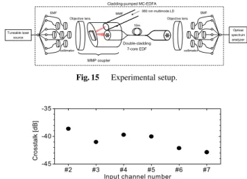
Fig. 16 Cross-talk for the centre core measured at 1630 nm.
cross-talk for the center core. Figure 15 shows the ex- perimental setup to measure amplification characteristics.
Length of the MC-EDF is set to be 10 meter for C-band amplification. The MMP coupler is set at input end of the MC-EDF. The MMF of the MMP coupler is connected with a 980-nm MM-LD. At input side, optical signal output from the TLS is connected one of 7 SMFs and is collimated by following lens and is focused on the end of the MC-EDF by a shared objective lens. At output side, optical signal output from the MC-EDF is coupled with SMF by a shared objective lens and one of seven collimators. Amplified sig- nal is measured by an optical signal analyzer. We measured coupling losses of optical signals for each core. To avoid absorption by erbium as far as possible, optical signal with wavelength of 1630 nm is used. Averaged coupling loss was 4.2 dB and maximum and minimum loss was 4.6 dB and 3.7 dB, respectively. Thus, maximum loss difference was 0.9 dB. Here, this setup has averaged coupling loss of 3.5 dB for a MCF. We evaluate cross-talk for the centre core as the worst case. Optical signal with wavelength of 1630 nm is input to one of 6 outer cores. We measure output power of the outer cores and the centre core. The ratio of the output powers is the cross-talk for each core as shown in Fig. 16.
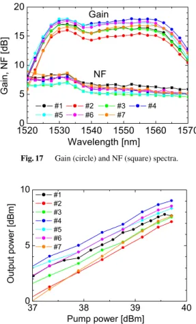
All the cross-talks were less than −38 dB. Total cross-talk was as small as −32.7 dB. We measure gain and NF spec- trum for all 7 cores. Pump power and signal power was held at 39.45 dBm (8.8 W) and−18 dBm, respectively. Figure 17 shows measured gain and NF spectra for all 7 cores. Wave- forms of gain correspond to that for conventional EDFA. In C-band, all cores have gain >14 dB and NF<9 dB. Next, we measure pump power dependence of saturation power.
Wavelength and power of optical signal was set at 1550 nm and −0.75 dBm, respectively. We consider that measured power is close to the saturated power because the measured gain is significantly smaller than the small signal gain shown in Fig. 17. Figure 18 shows the obtained pump power depen- dence. At pump power of 39.45 dBm (8.8 W), the maximum output power was 8.7 dBm. The averaged slope of the satu- rated power to the pump power is 2.2 dB/dB. The saturation
Fig. 17 Gain (circle) and NF (square) spectra.
Fig. 18 Pump power dependence of saturation powers for all 7-cores.
power is too small to amplify WDM signals. We found that further improvement of the slope is necessary to use the am- plifier practically.
We discuss the gain variation indicated in Fig. 17.
Three factors are considered as the reason of the variation.
One is variation of absorption coefficient among 7 cores, an- other is variation of the coupling losses between the SMF and the MC-EDF, and the other is distributional variation of pump power in the inner cladding of the double-cladding MC-EDF. Because the gain variation was about 3 dB for a core-pumped MC-EDFA, we consider that the main factor is the variation of absorption coefficient among cores. Ac- tually, maximum variation of the coupling losses of 0.9 dB is smaller than the gain variation of 3 dB. In addition, distri- bution of pump power in the inner cladding at the MC-EDF output end was almost flat as shown in Fig. 19(a) though that at the MMF end was Gaussian shape as shown in Fig. 19(b).
Full width at half maximum of the distributional power de- viation in the flat top area is 2.8% (−15.7 dB) to the aver- aged power. Next, we discuss the variation of NFs for the all cores. Major factor for NF is coupling loss at the input end and reabsorption of optical signal by erbium. Because the reabsorption is small enough at longer wavelength, NF for longer wavelength is caused mostly by the coupling loss.
Therefore, the variation comes from the variation of the cou- pling loss at input end. Finally, we discuss the contribution of core-pump excitation to gain. Ratio of a core-area to
Fig. 19 Near field pattern at the MC-EDF output end (a) and of the MMF end (b).
the inner cladding area is less than −27 dB (0.2%). When the pump power of 36.05 dBm (4.0 W) is input to the inner cladding, pump power for a core is less than only 9.05 dBm (8.0 mW). Therefore, we could neglect the contribution of the core-pump excitation to gain.
5. Conclusion
We investigate multi-core erbium-doped fiber amplifier (MC-EDFA) based on space division multiplexing technol- ogy. A excitation of erbium-doped region in MC-EDF is performed by one of two methods; one is core-pumping scheme, the other is cladding-pumping scheme. In the inves- tigation of core-pumped MC-EDFA, we realized high gain, wide bandwidth, and low noise figure MC-EDFA with low cross-talk of less than−45 dB. As a result, we can say that MC-EDFA with core-pumped scheme is feasible. In the investigation of cladding-pumped MC-EDFA, we demon- strated a cladding-pumped MC-EDFA using the MMP cou- pler which does not use objective lens for 980-nm pump light. The total cross-talk for the center core as the worst case was−32.7 dB. In C-band, gain and noise figure were
>14 dB and<9 dB, respectively, for all the 7 cores. The saturated power for 39.45 dBm (8.8 W) pump light was<
8.7 dBm. These results indicate that the developed MMP coupler enables to amplify all the 7 cores of the double- cladding MC-EDFA by cladding pump.
Acknowledgments
The research results have been achieved by “R&D of inno- vative infrastructure of optical communications”, the com- missioned research of National Institute of Information and Communications Technology (NICT), Japan.
References
[1] T. Morioka, “New generation optical infrastructure technologies:
“73.7 Tb/s (96×3×256-Gb/s) mode-division-multiplexed DP- 16QAM transmission with inline MM-EDFA,” ECOC2012, paper Th.3.C.4, 2012.
[4] K. Imamura, K. Mukasa, and T. Yagi, “Investigation on multi-core fibers with large Aeffand low micro bending loss,” OFC2010, paper OWK6, 2010.
[5] K. Takenaga, S. Tanigawa, N. Guan, S. Matsuo, K. Saitoh, and M. Koshiba, “Reduction of crosstalk by quasi-homogeneous solid multi-core fiber,” OFC2010, paper OWK7, 2010.
[6] T. Hayashi and T. Sasaki, “Design strategy of uncoupled multicore fiber enabling high spatial capacity transmission,” IEEE Summer Topical Meeting 2013, paper MC2.4, 2013.
[7] Y. Sun, R. Lingle, Jr., A. McCurdy, D. Peckham, R. Jensen, and L.
Gruner-Nielsen, “Few-mode fibers for mode-division multiplexing,”
IEEE Summer Topical Meeting 2013, paper MC3.1, 2013.
[8] S. Randel, R. Ryf, A.H. Gnauck, M.A. Mestre, C. Schmidt, R.- J. Essiambre, P.J. Winzer, R. Delbue, P. Pupalaikis, A. Sureka, Y.
Sun, X. Jiang, and R. Lingle, Jr., “Mode-multiplexed 6×20-GBd QPSK transmission over 1200-km DGD-compensated few-mode- fiber,” OFC2012, paper PDP5C.5, 2012.
[9] J. Sakaguchi, B.J. Puttnam, W. Klaus, Y. Awaji, N. Wada, A. Kanno, T. Kawanashi, K. Imamura, H. Inaba, K. Mukasa, R. Sugizaki, T. Kobayashi, and M. Watanabe, “19-core fiber transmission of 19×100×172-Gb/s SDM-WDM-PDM-QPSK signals at 305 Tb/s,”
OFC2012, paper PDP5C.1, 2012.
[10] K.S. Abedin, T.F. Taunay, M. Fishteyn, M.F. Yan, Z. Zhu, J.M. Fini, E.M. Monberg, F.V. Dimarcello, and P.W. Wisk, “Amplification and noise properties of an erbium-doped multicore fiber amplifier,” Opt.
Express, vol.19, pp.16715, 2011.
[11] Y. Tsuchida, K. Maeda, Y. Mimura, H. Matsuura, M. Ryo, K.
Aiso, and R. Sugizaki, “Amplification characteristics of a multi-core erbium-doped fiber amplifier,” OFC2012, paper OM3.C.3, 2012.
[12] K.S. Abedin, T.F. Taunay, M. Fishteyn, D.J. DiGiovanni, V.R.
Supradeepa, J.M. Fini, M.F. Yan, Z. Zhu, E.M. Monberg, and F.V.
Dimarcello, “Cladding-pumped erbium-doped multicore fiber am- plifier,” Opt. Express, vol.20, pp.20191, 2012.
[13] Y. Mimura, Y. Tsuchida, K. Maeda, R. Miyabe, K. Aiso, H.
Matsuura, and R. Sugizaki, “Batch multicore amplification with cladding-pumped multicore EDF,” ECOC2012, paper Tu.4.F.1, 2012.
[14] J. Sakaguchi, Y. Awaji, N. Wada, A. Kanno, T. Kawanishi, T.
Hayashi, T. Taru, R. Kobayashi, and M. Watanabe, “109-Tb/s (7×97×172-Gb/s SDM/WDM/PDM) QPSK transmission through 16.8-km homogeneous multi-core fiber,” OFC2011, paper PDP6B, 2011.
Koichi Maeda joined FITEL Photonics lab- oratory of Furukawa Electric, Chiba, Japan in 1989. From 1989 to 2011, he has been engaged in research and development of optical fibers.
From 2012, he have been mainly investigated multi-core EDFAs.
Ryuichi Sugizaki received his B.E. de- gree from Chiba Institute of Technology, Chiba, Japan, in 1990. In 1990, he joined Furukawa Electric Co., Ltd., where he has been engaged in research and development of optical fibers. He is now a group manager of optical fiber group, Fitel Photonics laboratory. He is a senior mem- ber of the Institute of Electronics, Information and Communication Engineers.