PAPER
A Closed-Form of 2-D Maximally Flat Diamond-Shaped Half-Band FIR Digital Filters with Arbitrary Difference of the Filter Orders
Taiki SHINOHARA†a),Nonmember, Takashi YOSHIDA††b),andNaoyuki AIKAWA†††c),Members
SUMMARY Two-dimensional (2-D) maximally flat finite impulse re- sponse (FIR) digital filters have flat characteristics in both passband and stopband. 2-D maximally flat diamond-shaped half-band FIR digital filter can be designed very efficiently as a special case of 2-D half-band FIR filters.
In some cases, this filter would require the reduction of the filter lengths for one of the axes while keeping the other axis unchanged. However, the conventional methods can realize such filters only if difference between each order is 2, 4 and 6. In this paper, we propose a closed-form frequency response of 2-D low-pass maximally flat diamond-shaped half-band FIR digital filters with arbitrary filter orders. The constraints to treat arbitrary filter orders are firstly proposed. Then, a closed-form transfer function is achieved by using Bernstein polynomial.
key words: 2-D diamond-shaped filter, maximally flat, half-band filter, arbitrary different filter orders, closed-form expression
1. Introduction
One of the basic operations in multirate digital signal pro- cessing is sampling rate conversion by upsampling and downsampling[1]–[4]. Especially, the 2 : 1 sampling rate conversion from the orthogonal to quincuncial sampling pat- tern is very important in the field of two dimensional (2-D) signal processing [5], [6]. 2-D low-pass diamond-shaped half-band FIR digital filters (2-D DH filters) are used to avoid aliasing after decimation. It is very easy to implement these filters because impulse response of them has a quin- cuncial sampling pattern and approximately half of the filter coefficients are zero.
Many design methods for 2-D DH filter have been proposed[7]–[18]. An optimization based design method [10],[16]–[18]are well-known. These methods realize a steep cut-off characteristic, however, it causes passband rip- ples that may distort input signals. On the other hand, many design methods for 2-D low-pass maximally flat diamond- shaped half-band FIR digital filter (2-D MFDH filter) have been proposed[11]–[15]. This filter can achieve high accu-
Manuscript received April 14, 2018.
Manuscript revised November 5, 2018.
†The author is with the Toshiba Electronic Devices & Storage Corporation, Tokyo, 105-8001 Japan.
††The author is with the Department of Medical and Welfare Engineering, Tokyo Metropolitan College of Industrial Technology, Tokyo, 116-8523 Japan.
†††The author is with the Department of Applied Electronics, Faculty of industrial Science and Technology, Tokyo University of Science, Tokyo, 125-8585 Japan.
a) E-mail: [email protected] b) E-mail: [email protected] c) E-mail: [email protected]
DOI: 10.1587/transfun.E102.A.518
rate extraction of input signal. This filter is often preferred for image signal processing because it usually has less ringing in the step response compared with filters having passband rip- ple. A design method of this filter was proposed by solving the linear simultaneous equations obtained from constraints about the magnitude flatness at(ω1, ω2)=(0,0)[11]. How- ever, in this method, the linear simultaneous equations need to be formulated and solved each time when design specifi- cation is changed. To solve this problem, design methods of this filter was proposed by formulating the closed-form trans- fer function based on Bernstein polynomial[13]–[15],[19].
There is no need to solve a set of linear simultaneous equa- tions.
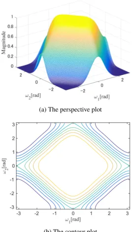
In recent years, 2-D MFDH filters is required to have the different filter order for each axis [12]. 2-D MFDH filters with different orders are required in some applica- tions, for example, interlace-to-noninterlace scanning con- verter in TV signal processing [12], [16], sampling rate conversion for different aspect ratio images, and sampling structure conversion for array systems. The design method of this filter by using linear equations was proposed[12]. In this method, the degree of freedom for frequency response of the filter increases according to difference of filter or- ders. Therefore, this method employs additional constraints at(ω1, ω2) =(0,0), in theω1 =ω2 direction and for equi- amplitude line. However, the difference of filter orders of this method only can be set among 2, 4 and 6. Furthermore, as shown in Fig. 1(a) and 1(b), this method realize the mag- nitude response having peaks which may distort an input signal.
In this paper, we propose a design method for 2-D linear phase MFDH filters with arbitrary difference of filter orders and monotonically decreasing magnitude response. First, we propose novel constraints which are imposed only at (ω1, ω2)=(0,0). Next, the proposed magnitude response is achieved as a closed-form solution by using Bernstein poly- nomial. The parameter of the proposed method is only the flatness degree for magnitude response at(ω1, ω2)=(0,0). Then, we show design examples to confirm that the proposed method can design the filters regardless the filter order differ- ence and realize the flat magnitude response. Furthermore, we show that all the impulse responses of the proposed filter has quincuncial sampling patterns.
Copyright © 2019 The Institute of Electronics, Information and Communication Engineers
Fig. 1 The magnitude response of (8×14) order 2-D MFDH filters designed by the conventional method[12].
2. Design Method
2.1 Definition of 2-D Half-Band FIR Digital Filters In general, the frequency response of a(2N1 ×2(N1+d)) order liner phase 2-D FIR digital filter is given as
H(ω1, ω2) = 2NX1
n1=0 2(N1+d)
X
n2=0
h(n1,n2)e−jω1n1e−jω2n2
= H0(ω1, ω2)e−jω1N1e−jω2(N1+d), (1) whereh(n1,n2),d, andH0(ω1, ω2)are the filter coefficients, an integer equal to or greater than 0, and the zero-phase frequency response. Here, the frequency response of the filter given by equation (1) is symmetric with respect to (ω1, ω2) =(0,0)in the frequency plane. Furthermore, the frequency response of equation (1) is symmetric with respect to theω1andω2axes because the coefficients of the linear phase 2-D FIR digital filter hold
h(n1,n2) = h(2N1−n1,n2)
= h(n1,2(N1+d)−n2)
= h(2N1−n1,2(N1+d)−n2). (2) Consequently, the frequency response of 2-D zero-phase FIR
digital filters is given as
H0(ω1, ω2)=
N1
X
n1=0 N1+d
X
n2=0
h(n˜ 1,n2)cosn1ω1cosn2ω2, (3) where ˜h(n1,n2)is a coefficient led byh(n1,n2)as shown in [13]. In this paper, we will introduce the design method for 2-D zero-phase DH filter because the filter coefficients of the linear phase filter are derived as time-shifted coefficients of the zero-phase filter.
A 2-D zero-phase FIR digital filter is said to be 2-D zero-phase DH filter if
H0(ω1, ω2)+H0(π−ω1, π−ω2)=1 (4) is satisfied for arbitrary ω1 and ω2. Equation (1) in- dicates that the frequency response is symmetric about (ω1, ω2,H0)=(π/2, π/2,0.5)in the space{(ω1, ω2,H0)|0≤ ω1, ω2 ≤ π}. Then, the coefficients of 2-D zero-phase DH FIR digital filters must satisfy[12]
h˜(n1,n2)= 1
2 (n1 =n2 =0) h˜(n1,n2)=0 (n1+n2=even)
. (5)
2.2 The Proposed Method
To design the(2N1×2(N1+d))order 2-D zero-phase MFDH filter, it is necessary to match the number of the coefficients and the number of constraints. That is, the frequency re- sponse of this filter must satisfy the following constraints:
H0(ω1, ω2)|ω1=0
ω2=0=1 (6a)
H0(ω1, ω2)|ω1=0
ω2=π =0.5 (6b)
∂iH0
∂ω1j∂ωi−j2 ωω1=0
2=0
=0 i=2,4,· · ·,2(N1+d−1) j =0,2,· · ·,2(s(i)−1)
! .
(6c) Note that the constraints at(ω1, ω2)=(π, π)and(ω1, ω2)= (π,0) are derived to satisfy (4) from (6). In (6c), s(i) is the flatness degree for the magnitude response at(ω1, ω2)= (0,0)and(ω1, ω2)=(π, π)and given by
s(i)=
i
2+1 (i≤2(N1−1))
m(i) 2N1 ≤i ≤2 N1+d 2
! !
N1−m(4N1+2d−i)+1 i >2 N1+d 2
! !
,
(7) wherem(i)is an integer parameter to control the shape of equi-amplitude line, and it is determined as follows:
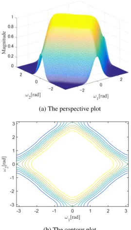
Fig. 2 The magnitude response of(8×14)order 2-D MFDH filter de- signed by the proposed method.
1. m(2N1)=N1
2. ifdis an even integer,m 2
N1+d2 =bN12+1c 3. For 2N1 < i < 2(N1 +d/2), m(i) is set to satisfy
m(i−n)≥m(i) >bN12+1cwith an even positive integer n
In the abovem(i)decision rules,bxcdenotes the maximum integer not exceedingx. From the last rule, the number of m(i) to be set is b(d−1)/2c. Therefore, there are (N1− bN1/2c −1)b(d−1)/2c combinations of constraints (6c) by changing parameterm(i).
In this paper, a closed-form frequency response satisfy- ing (6) is proposed using Bernstein polynomial as
H0(ω1, ω2)=
N1
X
n1=0 N1+d
X
n2=0
f(n1,n2) bn1,N1(x)bn2,N1+d(y),
(8a) where
bi,N(x)= N i
!
xi(1−x)N−i,(0 ≤i ≤N) (8b) x= 1−cosω1
2
Fig. 3 The coefficients of(8×14)order zero-phase 2-D MFDH filter designed by the proposed method.
Fig. 4 The magnitude response of(8×16)order 2-D MFDH filter with m(10)=3.
y =1−cosω2
2 .
In above equation,a
n
is a binomial coefficient given as
a n
!
=
a(a−1)(a−2)· · ·(a−n+1)
n! (0<n≤a)
1 (n=0)
, whereaandnare an integer. In (8a), f(·)is the Bernstein coefficient derived as:
Fig. 5 The magnitude response of(8×16)order 2-D MFDH filter with m(10)=4.
f(n1,n2)=
1 ,(n1,n2)∈N
0 ,(N1−n1,N1+d−n2)∈N 0.5 ,otherwise
(8c)
N ={(n1,n2)∈N|0≤n1+n2≤N1+d−1, 0≤n1 ≤s(2n1+2n2)−1}. (8d) It is shown in the appendix that derivation of f(·), and (8a) satisfies (4).
By substitutingx=(2−z1−z1−1)/4 andy =(2−z2− z−21)/4 in (8a) and (1) , we can obtain the coefficients of the proposed filter.
3. Design Examples
In this section, we will illustrate some magnitude responses of(2N1×2(N1+d))order 2-D MFDH filters designed by the proposed method.
Example 1:In this example, we compare the proposed method and the conventional method forN1 =4 andd =3 [12]. The magnitude response of the conventional method are already shown in Fig. 1(a) and 1(b). In this case, the parameterm(i)to be set is onlym(10). From the decision rules of m(i), m(10) is set as 3 or 4. Figures 2(a) and 2(b) show the magnitude response of the proposed filter
Fig. 6 The magnitude response of(8×18)order 2-D MFDH filter.
with N1 = 4, d = 3 and m(10) = 3. It is clear from Fig. 1(b) that the magnitude response of conventional filter is not monotonically decreasing at (ω1, ω2) = (0,0). On the other hand, it is clear from Fig. 2(b) that the magnitude response of the proposed filter is monotonically decreasing over the whole frequency. Figure 3 illustrates the coefficients of the proposed filter. From Fig. 3, it is confirmed that the proposed method can achieve the quincuncial sampling pattern as same as the conventional method.
Example 2: In this example, we illustrate the 2-D MFDH filter with d ≥ 4 design by the proposed method.
Such filter can be designed only by the proposed method.
In the case of design of filter with N1 =4 and d =4, the parameterm(i)to be set is onlym(10). From the decision rules ofm(i), the value ofm(10)is 3 or 4. Figures 4 and 5 show magnitude response of the proposed filter withN1=4, d = 4 andm(10) = {3,4}, respectively. From Figs. 4(a), 4(b), 5(a) and 5(b), it is confirmed thatm(10)controls the shape of the equi-amplitude lines.
Moreover, Figs. 6(a) and 6(b) show magnitude response of the proposed filter with N1 =4, d =5, m(10) =4 and m(12)=3 and Figs. 7(a) and 7(b) show magnitude response of the proposed filter with N1 = 9, d = 5, m(20) = 7 and m(22) = 5. From these figures, it is confirmed that 2-D MFDH filter with arbitrary d can be designed by the proposed method. Note that all of these filters are half-band
Fig. 7 The magnitude response of(18×28)order 2-D MFDH filters.
characteristics and the filter coefficients of each filter has a quincuncial sampling pattern.
4. Conclusion
In this paper, we introduced a design method for 2-D MFDH filters with arbitrary different filter orders. To solve this problem, we proposed the new flatness constraints. Then, a closed-form frequency response with arbitrary filter or- ders were derived. The parameters of the proposed method arem(i)which determines the shape of the equi-amplitude line, andN1. Through design examples, it is confirmed that the proposed method can realize monotonically decreasing magnitude response for arbitraryd. Furthermore, it is also confirmed that the proposed method can realize various equi- amplitude line by settingm(i), and the line approaches to the straight with appropriatem(i).
References
[1] F.J. Harris, Multirate Signal Processing for Communication Systems, Prentice Hall PTR, 2004.
[2] S.S. Barpanda, B. Majhi, and P.K. Sa, “Region based feature extrac- tion from non-cooperative iris images using triplet half-band filter bank,” Optics & Laser Technology, vol.72, pp.6–14, 2015.
[3] B. Song, “Design of 2-D perfect reconstruction diamond-shaped and fan-shaped FIR filter banks,” Proc. 2nd International Congress on Image and Signal, pp.1–4, Oct. 2009.
[4] J.H. Lee and Y.H. Yang, “Design of 2-D interpolation/decimation filters using a general 2-D digital allpass filter,” Digit. Signal Process., vol.22, no.5, pp.847–858, 2012.
[5] T. Yoshida, “Basics of image signals,” J. Inst. Image Inform. TV.
Engnr., vol.67, no.1, pp.36–40, Oct. 2013.
[6] G. Tonge, The sampling of television images, IBA E&D Rep., 112/81, 1981.
[7] R. Matei, “A new design method for iir diamond-shaped filters,”
Proc. 18th European Signal Processing Conference, pp.65–69, 2010.
[8] N. Rajapaksha, A. Madanayake, and L.T. Bruton, “2D space–time wave-digital multi-fan filter banks for signals consisting of multiple plane waves,” Multidim. Syst. Signal Process., vol.25, no.1, pp.17–
39, 2014.
[9] T. Chen and P. Vaidyanathan, “Multidimensional multirate filters and filter banks derived from one-dimensional filters,” IEEE Trans.
Signal Process., vol.41, no.5, pp.1749–1765, 1993.
[10] S.M. Phoong, C.W. Kim, P. Vaidyanathan, and R. Ansari, “A new class of two-channel biorthogonal filter banks and wavelet bases,”
IEEE Trans. Signal Process., vol.43, no.3, pp.649–665, 1995.
[11] T. Yoshida, A. Nishihara, and N. Fujii, “A design method of 2-d maximally flat diamond-shaped half-band fir filters,” Trans. IEICE, vol.73, no.6, pp.901–907, June 1990.
[12] K. Inui, T. Yoshida, A. Nishihara, and N. Fujii, “Design of 2-D maximally-flat diamond-shaped half-band FIR filters with rectangu- lar support of impulse response,” Trans. IEICE A, vol.77, no.10, pp.1336–1345, Oct. 1994.
[13] T. Cooklev, T. Yoshida, and A. Nishihara, “Maximally flat half-band diamond-shaped FIR filters using the bernstein polynomial,” IEEE Trans. Circuits Syst. II, Analog Digit. Signal Process., vol.40, no.11, pp.749–751, Nov. 1993.
[14] S. Samadi and A. Nishihara, “Explicit formula for generalized half- band maximally flat diamond-shaped filters,” Proc. 2000 IEEE In- ternational Symposium on Circuits and Systems, vol.3, pp.355–358, May 2000.
[15] S.C. Pei and P.H. Wang, “Design of arbitrary cutoff 2-D diamond- shaped fir filters using the bernstein polynomial,” IEEE Signal Pro- cess. Lett., vol.7, no.11, pp.310–313, 2000.
[16] M. Tsuchiya, “A design technique for half-band fir filters with Equi- ripple passband amplitude,” J. Inst. Image Inform. TV. Engnr., vol.49, no.6, pp.772–780, Oct. 1995.
[17] T. Hung, H.D. Tuan, and T.Q. Nguyen, “Design of half-band diamond and fan filters by SDP,” Proc. 2007 IEEE International Conf. on Acoustics, Speech and Signal, pp.901–904, Feb. 2007.
[18] M.A. Platas-Garza and J. Rodríguez-Maldonado, “Design of flat halfband filters with sharp transition and differentiators through con- strained quadratic optimization,” Computación y Sistemas, vol.21, no.2, 2017.
[19] R.T. Farouki, “The bernstein polynomial basis: A centennial retro- spective,” Comput. Aided Geom. Des., vol.29, no.6, pp.379–419, 2012.
Appendix A: Derivation of Bernstein Coefficients(8) From (4) and (8a), f(·)must satisfy the following relation- ship:
f(n1,n2)+f(N1−n1,N1+d−n2)=1. (A·1) From[14], the 2kth partial derivative of (8a) is given as
∂2kH0
∂ω12r∂ω2(k−r)2
= (2N1)!(2(N1+d))! (2(N1−r))!(2(N1+d−k+r))!
·
N1−r
X
n1=0
N1+d−k+r
X
n2=0
Xr
l1=0 k−rX
l2=0
2(N1−r)
2n1 2(N1+d−k+r) 2n2 2r
2l1 2(k−r) 2l2
N1−r
n1
N1+d−k+r n2
·(−1)2N1+d−n1−n2−l1−l2 f(n1+l1,n2+l2)
·bn1,N1−r(x)bn2,N1+d−k+r(y) . (A·2) From (8b), we haveb0,N(0)=1, so that we obtain
∂2kH0
∂ω12r∂ω2(k−r)2 ωω1=0
2=0
=
r
X
l1=0 k−r
X
l2=0
r l1
! k−r l2
!
f(l1,l2).
(A·3) From (6a), (6c), (8a), (A·1) and (A·3), we obtain
f(n1,n2)=
1 ,(n1,n2)∈N
0 ,(N1−n1,N1+d−n2)∈N . (A·4) On the other hand, there are only three combinations ofn1 andn2which satisfies(n1,n2)<N and(N1−n1,N1+d− n2)<N, i.e. (n1,n2)=(N1,0),(0,N1+d)for anyN1and d, and (n1,n2)= (N1/2,(N1+d)/2) for evenN1 and even d. Hence, from (A·1), we have (A·5),
f(N1,0)= f(0,N1+d)=0.5(for anyN1andd) f N1
2 ,N1+d 2
!
=0.5(for evenN1and evend).(A·5)
Appendix B: The Proof that(8a)Satisfies(4) We obtain from (8a)
H0(ω1, ω2)
= X
(n1,n2)∈N
bn1,N1(x)bn2,N1+d(y)
+1
2bN1,N1(x)b0,N1+d(y)+1
2b0,N1(x)bN1+d,N1+d(y) +1
2bN1/2,N1(x)b(N1+d)/2,N1+d(y) (A·6) H0(π−ω1, π−ω2)
= X
(N1−n1,N1+d−n2)∈N
bn1,N1(x)bn2,N1+d(y) +1
2bN1,N1(x)b0,N1+d(y)+1
2b0,N1(x)bN1+d,N1+d(y) +1
2bN1/2,N1(x)b(N1+d)/2,N1+d(y). (A·7) Then, all these summations exhaust all possible values for n1andn2.
H0(ω1, ω2)+H0(π−ω1, π−ω2)
=
N1
X
n1=0 N1+d
X
n2=0
bn1,N1(x)bn2,N1+d(y)=1 (A·8) From (A·8), this equation is always equal to 1[13].
Taiki Shinohara received the B.E. degree and the M.S. degree in electrical engineering from Tokyo University of Science, Tokyo, Japan, in 2016 and 2018 respectively. Currently, he be- longs to the Toshiba Electronic Devices & Stor- age Corporation. His research interests were in the area of digital signal processing.
Takashi Yoshida received the B.E. degree, the M.S. degree and Dr. degree in electrical en- gineering from Tokyo University of Science, To- kyo, Japan, in 2011, 2013 and 2016 respectively.
Currently, he is a research associate in the De- partment of Medical and Welfare Engineering, Tokyo Metropolitan College of Industrial Tech- nology. His research interests are in the areas of digital signal processing. He is a member of IEICE and IEEE.
Naoyuki Aikawa received the B.E. degree from Yamanashi University, Yamanashi, Japan, in 1985 and the M.S. degree in electrical en- gineering from Tokyo Metropolitan University, Tokyo, Japan, in 1987, and the Dr. degree in electrical engineering from Tokyo Metropolitan University, Tokyo, Japan, in 1992, all in elec- trical engineering. Currently, he is a Professor in the Department of Applied Electronics, Tokyo University of Science. His teaching and research interests are in the areas of digital and analog sig- nal processing and education. He is a member of IEICE, IEEJ, SICE and IEEE.
![Fig. 1 The magnitude response of ( 8 × 14 ) order 2-D MFDH filters designed by the conventional method [12].](https://thumb-ap.123doks.com/thumbv2/123deta/5634028.1501473/2.892.117.386.120.589/magnitude-response-order-mfdh-filters-designed-conventional-method.webp)