NII-Electronic Library Service
[M
ve
it
R]
Jouinat of Structural and Construction e"refi\kesrsXasgewGMUDC:624.131.ss:cr4.o4z7:seo.34 E"gineeringNo,349,March,1985
rg
34g e-main 6o ij3A'
'
'
SOIL-STRUCTURE
INTERACTION
ANALYSIS'
'
BY
GREEN
FUNCTION
-Parametric
Study
of theInfluence
by
Base
Mat
'Thickness
andSoil
by
KIYOSHI
MUTO*,
TOSHIO
KOBAYASHI**,
and
MITSUHARU
NAKAHARA***,
Mem6ers
ofAIJ.
'
'
1.
INTRODUCTION'
In
theseismic response analysis of massive and rigid structures such as anuclear reactorbuilding,
itisimportant
toevaluate the'dyna'mic
interqction
effectbetWeen
soil and structure adequately.,
As an analytical method, we have suggested the.methodof
discretized
Green
functionby
which thereaction stress distributionanddeformation
of the spil surface'canbe
treatedas unknown fagtors.Then,
the soil・stTucture'
interaction
a.nalysis canbe
conducted.・
'
In
thisreport, the effect of a reactorbuilding's
base
matfoundation
response issurveyed through a parametric studybased
onbase
matfoundation
thicknessand soil stiffness,'
2.
0UTLINE OF ANALYSIS..
2,1
Analytical
Theory
3), 7), 10) i a)Dynamic
characteristics of soilThe
dynamic
characteristics ofSo'il
are obtainedin
theform
of afrequency
depenclent
stiffness matrix, corresponding tothe each node of the base mat foundation.The matrix isbased on the discretizedGreen
Functionmethod, where soil is
,considered
a semi-infiniteglastic
continuum. Figures 1 and 2 show the excitation.b}
Dynamic
chaTacteristics ef structure'
.The
dynamic
characteristics of the structure is obtained using mass and stiffness'matricesby
FEM with shellelements.
'
・
Stillmore,
thedegrees
offreedom
are reduced tgthehori,zontal
and veTticaldegrees,
expressing rocking response.(Referred
3),)'
'
-.-
-L
-..
l'
suriacF.e'.Wa : vertical etciting ferct iot
:vertical responsedisplacement
Vv,eFve;"t= Ke(.) uv ei"`
Ket-) ;vertical stitfness matrix of soil
'
'
'
Fig.1 Explanationof VerticalExcitatien
..1
VHsurfacb)
--
tt
''
.
FHei"t;haritontal exciting feree'
U'Hei'[;herizontal
tespettse dispLacement
'
FHeiaj=Kftt") UHei"t
・
'
'
Kfi("J:horitenta1 stiffness matrix ef soi]Fig.2 Explanation of HbrizentalExcitation
t---- Dr.Eng., Member of the
Japan
Academy'
# Dr.Eng., Deputy
Chief,
Muto Ihstitute of Structural'Mechanics,KajimaCDrpo[ation **i ResearchEngineer, Muto InstitutebfStrueturalMechanics,KajimaCorporatien'
-101-NII-Electronic Library Service
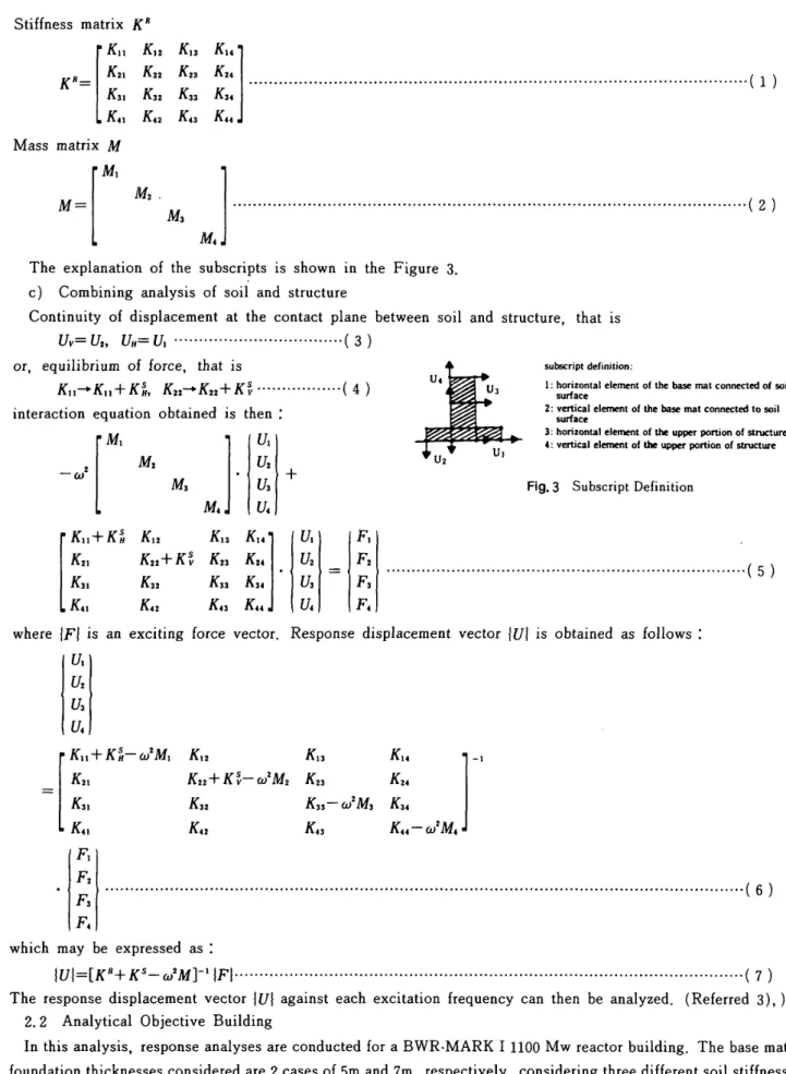
Stiffness
matrixK"
rKu
Ki2Kn
K"1
.R=l:il
:li
:il
j:lll
...
"..."-""".
-"".H・.
-・-・
・---・---・-
-・(i)
LK"
K,i
Kls K"J Mass matrixM
M=[
M'
M}
M,
Ml](2)
The
explanation of the subscriptsis
shownin
theFigure
3. c)Combining
analysis of soil and structureContinuity
ofdisplacement
at the contact planebetween
sQil and structure, thatis
Uv=ca,
U){=U・・・・-・--・・-・・-・・・・・・・-・・・・・・-(3)
or, equilibrium of
force,
that isKii-'Kti+Kil,
Kn'Kt2+Kf・'"'''''''"'''''(4>interaction
equation obtained isthen:-.,
[
"i"'
"'
,4i]
2'
Kl:+Ki
.K,ij..,
,Kil
,K,tll
Sl
k'
iK3i
K3!
K3a K,J'a
==a
LK"
Kn
K,3
K"J
u
E
u-U3
Uz u]
subseriptdefjnjtion/
1:horiionlaleterrwnt otthe basernatconrtected ofsui: surtace2/
vertical elerrRntofthehasemHt conneetedtosoil surtact3/
horiionta1elcment oftheupper pbrtionofstrueture 4/vertical elerrreqtafbeupper part;onotimt"re Fig.3 SubscriptDefinition
-".""""""""""H"..H"""".hH-"H",""..---・・--・(5)
where
iFI
is
an excitingforce
vector.Response
displacement
vectoriUiis
obtained asfollows:
z
rKn+Kn-diMi
K"Kis
Ku
1--lK,,
-tKsi
Kn+Ki-wZM2Ki3
Ku
1
Ksi
Ki3-w2M3
K"
1
L
K,,
K"
Kn
K"-w2M-J
I;:
.,,..,-,
..,..
...,,"
.,".
..,,,.
H,"
.",..,,,-,-,,,..,..-".,.,.,,,.,,,.,...,,...".,."..
・.
-・(6)
which rnay
be
expressed as:IUI=[Kn+KS-to!M]-iIFF・・・・・・-・・-・・-・・t・t・・・-・・・-・・・・-・-・t・・・・-・-・・・-・・・・・・・-・・・・・---・--・・・-・・・-・・・・・・-・・----・-・・(7)
The response displacement vector
iUl
against each excitation frequencycan thenbe
analyzed.(Referred
3),)
2.2 AnalyticalObjective BuildingIn
thisanalysls, response analyses are conductedfor
aBWR-MARK
I
1100
Mw
reactorbuilding.
Thebase
rnatfoundation
thicknessesconsidered are 2cases of 5m and 7m, respectively, considering threedifferent
soil stiffness cases.Mainstructural partsconsist of concrete outer,
inner
and shield walls with abase
matfoundation.
This
structure'is 80mx80 min
plan and 6s m or 67 min
height
with a totalweight of about300,OOO'tons.
Figure 4 shows the cross section of the reactorbuilding.
NII-Electronic Library Service FL-S,aH FL]6,O// FL27,O FLIS.eIE[IEIi! FL 9,O FL O,O FL
-1,O
FL-IS.O FL-20.0 fi soo mo'an
eoO.. fi・
10colloelsoetloe2poeTooo irfi
1tm1000 loooteno g lteo1suO'
Tsoeltco'g'
ttoDleoo 1anleoo tp 1toO leoo1sw oi ipm
am'
UNIT:mm
Fig.4 Structura]CrossSection
(A-A)
'
'
'
In
the analyses, symmetryis
assuihed about axes`A-A'
and tB-B', of the aforementionecl
figures,
The
uppeJleft
quadrantisevaluatedby
theFEM method by applyingits
mass matrix and thestiffness matrices ofthe walls, thebase
mat foundation,the floorsand thepoolwall.
Figure
5 shows thequaitersection of thebuilding
analyzed.'
Figures 6 and 7show the mesh layoutand the node and element of the
FEM
moclel,- respectivelY.
2.3
Analytical
Condition
a>
Earthquhke
Analy$i$
An
artificial earthquakei,s
considered, which wasdeveloped
by
"Improvementand
Stanclarization
Com-mittee of MITI" in 1969, and isclassified as an Sl earthquake locatedin a high seismicdistrict.
Characteristiqsof thisearthquake are as follows;
Magnitude M=t7.0
Distance
from
epicenter A=20km
Phase
EL
CENTRO
1940NS
Duration
25.SecondsMaximum Acceleration 267.4
gal
yx
zT
'
?
!x
Fig.5 IclealizedStructure
(114
Portion)A)B2F{FL.-15.0m} r--=
I
I
l
l
h:----:i
C)Bl,F(FL..5.5m} B)BIF(FL"7.dn).t.t
lL-E)2F(FLLD
).
1F(FL.O.ori)
l
L"
.9.0m) r---T1
1
ll
ll
L--r--1
Fig.6' F)3F(FL.18.om} L---"G)4F(FL.27..Om)H)CRF(FL.36
dn)I)RFCFLFEM Mesh Layont:45.0m)
Figure
8
shows the aeFeleration timehistory
of.the
earthquake and the acceieration response spectr4 using1%
and5%
damping.
b)
Damping
Damping
value of the reactorbuilding
isassumed 5% anddissipation
dalnping
of the soilisevaiuated using its stlffness matrix.c)
Response
analysis methodResponse
anal'ysis of the earthquakeis
conductedin
thefrequency
domal'n
since the soil's stiffness matrixis
found
in
thefrequency
domain.
The
earthquake canbe
transformedfrom
its
timedomain
toits
frequency
domain
by
FFT
rnethod.,Therefore
the response of the earthquake can alse be obtained initsfrequen¢ydomain.
Andby
inverseFourier
transformatibn,the response in turn, canbe
transformedback
intoitstirnedomain.
NII-Electronic Library Service A) FRAME
¢
C)
FRAME@
B) FRAMEQ
D)
FRAME@
v
E) POOL WALLEii
F) OBLIqUE WALLD)
SHIELD
WALL
Fig.7 FEMMeshLayoutd)
Soil
constants
The
soilis
considered a semi-infinite elastic media and threesoil constants are considered as $hewn inTable
1.
3.
ANALvrICAL RESULTSBY
THE
HORIZONTAL
EARTHQUAKE
3.1
Acceleration
Transfer
Function
Figures9,10show the acceleration transfer
function
ofthemain pointsof thebuilding
in
thecase ofbase
mat thicknessis
7
m.In
thesefigures,
the results of threecases(V,=500
mls, 1000 m/s, 2000 mls) are compared,Hz,
12.
5
Hz
respectively.Hz
and 6.2Hz
respectively.In
thehjgh
frequency
Figure
11 shews the acceleration transferfunction
There
are no significantdiff
peak grow
larger
according to theincrease
ofVs.
3,2 Dynamic Respense
by
the H6rizontalThe
maximum response ofbase
matfoundation
areFigure
12
MAXIMUM RESPONSE VERTICAL reactorbuilding
Figure
13
MAXIMUM
RESPONSE
BENDING
Figure 14 MAXIMUM RESPONSE REACTIONFigure
15
MAXIMUM
RESPONSE
REACTION
4.
STUDY
OF
RESULTS'
4,1
Study
of theBase
Mat
Foundation
Uplift
(gnl}2Cmo
1ooO o O.Ol{gal)500o
"=7.0Dt20kmphase:Elctntro1940NS ht1x1h;5S O.05 O.10A)
RESPONSE
O.50 1.00SPECTRUM
(sec) 2,oo s.oeF"'e)me::Tx"":,:t"'""-'""'"`"-i-'-w"
o Fig.82s(Sec)
B)
ACCELERATION
TIME
HISTORY
InputEarthquakeGround MotionafterMITI's Cemrniteeon "lmprovement
and Standardizatien of LightWaterReacter
TABLEI Seil
Constants
ease 1 2 3
ShearVelocityVs(mtsec)50010002oee
ShearModulusGCMPa) soo2000soeo
Density p{MglmS}2.0'2,O 2,O
Poisson'sRatiov O,4O,4 O.4
The
first
peakfrequencies
inhorizontal
direction
are 2.6
Hz,4.
6
Hz,5.
6
Hz and thesecond ones are 10.5Hz, 11.5Transfer
function
of verticaldirection
shows thatthefirst
peakfrequencies
are3,
4
Hz,
5.
5
domain,
thecomplex modes aie expressed.of themain pointsof the
base
mat.erence and no peak
in
thehorizontal
direction,
but
in
theverti ¢aldirection,
thefirst
Earthquake
depicted
in
theFigures
asfollows:
ACCELERATION caused by rocking motion of the
MOENT
(M.)
STRESS
(a),
VERTICALSTRESS
(r),
HORIZONTAL
The
study of uplift isconducted using the summation of the response of3
casesNII-Electronic Library Service
{GIG)8.0
6.0 4.e 2.0 oo510 15 20 HORIZONTAL{G/G)8.0
6,O 4.o 2.0 25(Hz)oo oos'100s-T991'' t'ttettN ,,1e.-,,t500mtsrr(
's-.-t .,,,..--i-t. s10 15 20 HORIIONTAL 25(Hz>{GIG)3.0
2.0 1.0 oo 1oooms 104 TN :t --tsllt-eep]9QPm4,E,SggE÷
E "-t-,,.-t'--s'
.'-dt't"s'. 'tt'. ..--510・ISVERTICAL20
(G/G)3.0
2.0 1.0 25{Hz)oo/C!!lltXiiions(99
.,/',, r,1000tr"rs-1-tl' '''.r:s---''-s' .-i t-ttJtvt'N. INNERWALL
Fig.9 AccelerationTransfer
'
510 15VERTICAL OUTER Function{3
F)WALL 202SCHz) ''
CGIG)s.o
6.0 4.0 2.09o
50orVss 121' T ii,1000rnifsL,2S?ngsN
'v',ti-:etl-''t:-I-,t.s-s;---i--..
slo TS 2a RORIZONIAL{GIG)8.0
E.O 4.0 2.0 o25O(Hi) 2uas,100s 51 V' 1 N tu 'J 150dnVs 't'.Ittt
:,
,,,'N.. ---'-s.. s10 IS' 20' HORIZONTAL 2S(Hz)tt
'
{GIG)3.0
2.0 1.0 oo 200 72 ST : 100ontSN 'u lt'',EggN4i' t)' 1'.ts'-jslt`tt - v---s10 15VERTICAL20 (CtG)3.0 z.o1.e
o25O{Hz)INNER
WALL, Fig.10 Acceleration ・mptsrs671 100Cimtsv
''50s -st f--tl' I-x-` --'-t.'-J.-'--. ''..'"--Transfer s10 15VERTICALOUTER
WALL Function(1
F) 2025(Hz)105
NII-Electronic Library Service f,vt=5M (G/G)6.0 4.0 2.0 oo
{G/6)2.0
1.e 510 15 20 HOR[ZONTAL r2000mtsrer'looemsT17x N t7 5eOms .tti- rt,-s---o o s su o zoo-x
-o
1Vs
=500
-xVs
= 1000 M/seccatG)5.04.0
2.0 a o 2eOms.'1:tw ,1000ms t''500msj-t...N.V.----.-o---.
25(Hz) CGIG} 2.0 1.0 510 15 20 HORIZeNTAL ttJ ,v 25(Hz)2g9QmLE`f/looomsTlr
x tyr e'tl/sggmLg1-".--j---'.--.
10 15 20 2S o s 10 IS 20vERTIcAL
{H2}
vERTIcALINTgERWALL
OUTER
L"ALLFig.11 AccelerationTransferFllnction
(Base
Mat)'
t=5M " t=7M tT GAL o 200':
rV
oM/secSALe
GALoE zoe 20 o-x
't 25(Ht} M/m.i.vt=7M
te o-・--xoZ7
ivs=1'ooo
lsec
t・m/meee oii ,Y'1 GAL.Y1 om o e 2oo 2e o o・--x---x
't'
/.T
,v-・-:
M/sec.v
..-x
/' t,ofm!Ftl
e,
oo--x--tt'
vs='i2000M/sec-・-:EQ.
t.rnfmI:oo t・ulm1:. t・mlrne,.t
tvs=2ooo Mlsec
kt'
dwfig.
12
Maximum ResponseVerticalAcceleratlon Fig.13 Maximum ResponseBendingMoment(.My)
seismisity ;
-O.2
g, andSl
earthquake response)Figure
16
shows the results andin
the case of the 500 mls soil shear velocity, the soil stresses a[e allin
compression, Inthecase of 1000mls, partialtension occurs at theedge of thebase
matfoundation.
And
in
the case of2000
mls, the edge of thebase
mat and the near shield walllie
in a narrow tension area.
4.2
ln
Plane
Deformation of 3rd FloorFigure
17
shows the maximum response accleration anddisplacement
of the outer wall whichis
perpendicularto the eaithquakediiection.
This result shows that the
harder
the soil stiffnessbecomes,
larger
accelerations, and smallerdisplacements.
Both
acceleration anddisplacement
become
larger
from
the node(99)
of outer wall tothenode(113)
atthecenter of thebuilding,
and'it shows thatthefloor's
in-planedeformation
is
quite signifi ¢ant.This
tendencyis
thesame in-106-NII-Electronic Library Service t=5M t=7M
iv
v MPa'fho.4 o.x
O.tl e. 'to.10o.t4 T,o b.Ol
: VS=
5PO
MIsec O.IEMPa
e,,
,.!v
VS
= 1000 Mlsec,v
HPatt.oO.4li,l40
-xo.oT1
o.s3 Eq.-MPaoO.4 e-. i-o
Fig.14 iV ME60'o
xai o.e;-'X e・"vs=2000
M/secMaxirpurpResponseReactionStress
t=5M
'
t=MPd
't
..Y
t=5M t=7M
!Y
Mpe i,r HPae.,
-x
VS=500
Mlsec./Y
MPeE:.4
-x
vS =1000 M/secIV' MPa fjV MPa
,
e.,
x
vs=2ooe Mlsec Eq.
-Maximum Respohse ReactienStress
(a)
HorizontalE-q-lt80.
kEV PLAN(3rd FLOOR}
'
l:.,o
-x
'
N MPat.4 1.N e,(
a) Vertical'
7M
MPa:.4 o-t l !.Yc
.e,
7tEJ ' Fig.15 4・-x
VS=500E:.4
M/secJV
MPetit
o--i i-x
"o
/ vS =1000
M/sec x HPaE.4
MPeI.4 @ @@
o
@ vs- @ .-・'-・Soo1000---s・s-n.2ooe--Ls.h NNNN Cmtsec)@.xsl @ ,1s1
,tt
'
1 1 ,・o
oroo-ooeooam1000:teooo.toD.-Oo.wo.eo1,ooAcceleration(gal)t=5m
(cm) Displacement @vs=2ooo Mlsec
kt・
@
Fig.16 Reaction Stress
(Dead
Weightx
(1-O.2)
G-S,Response)o
o tooqco seesoo /ooelloo
-
o O.tOO.ope,SO o.eOl,OOPhOit.hk.eCsa,SeesS.
8fhis5srnheilZdthZtl'lhebtahS,lck:.a,ts
l?\h",dabti.O,"e
Accieration C9t":}7'mDispiacementC"")
mat can not reduce thefloor'sin-plane
deformation
of Fig:17 MaximumResponse
Acceleration andDisplacement
(3rd
Floor)the ttpper structure.
5.
CONCLUStON
'
'
The
authorshave
suggested the method ofdiscretized
Greenfunction
as thesoil-structure interactionanalysis method inthe seismic response analysis of a reactor building.Inthisreport psingthismethod, the parametriqstudy of the effects ofbase
matfotindation
thickness and soilstiffnessare conducted.Mosit
concernlie
in
the area ofthebase
ihat
foundation.
The
study of results are asfollows:
1.
There
are no upper structure effectsfrom
the respense and reaction stress of thesoilby
employingdifferent
-107-
,vs-=,, -・.soe..N.-+.. x'100ti..2ooO.-.--gh'NNNN
{mtsec)@--.N
xx
.101/-'"11)
,1t,'NII-Electronic Library Service
base
matfoundation
thicknesses.However,
theresponse stressofbase
mat itselfhas
considerable effecton ttiebase
mat fou"dationstress.
2. The
harder
the soil,becomes
larger
accelerations, and smallerdisplacements
on the upper structure, Also, theupper $tructurelines
offorce
aredirected
onto the soil.In
the case of soft $oil, the reaction seil stress aredistributed
evenly over the entire reactor building area.
3.
Common
characteristics of all cases, in-pianeshear deformation of the upper flooroccurs and in-plane acceleration anddisplacement
at thecenter of thestructurebecome
larger.Also, thesoi! stresses around theshield wail of thebase
mat foundationbecome
laTgebecause of the effect of theshield wallbending.
Reterences L 2. 3. 4. 5. 6. 7. g. 9. 10. IL 12. I3. I4. ]5. 16. 17. BycroftG,N., : "Ferced Vibrations
ofa RigidCiTcularFeotingon aSemi-InfiniteElasticSpaceand on an ElasticStraturn" PhilosophicalT[ansactions of the RoyatSecietyof London, Vol. 248, SeriesA, No. 948,
Jan.
1956, pp. 327-368Juan
E.Luco,Russell,A. Wastmann ;"Dynamlc Responseef CircutarFaotings"Journa]
ef the EngineeringMechanies Divisionpp. 1381-1395, l971KobayashiT.,
"Dynamic Soil-StructureInteractionAnalysis basedon discretizedGreenFunction" Transactions of the ArchitecturalInstitute,Ne. 302, April1981
(in
Japanese)
Kobori T.
,
Minai R., Suzuki T. etal;"Dynamical GroundCompliance
of rectangular・Foundation on a semi-infinite Elastic Mediurn1'
(Patt
1), Bulietinof Disaster Prevention Instituteof University of Kyoto, Vol. IOA, 1967(in
Japanese)
Lamb H.:"On
the Propagationof Tremorsover theSurfaceof an ElasticSolid"PhilosophicalTransactionsof the Royat Society,London, SeriesA, Vol. 203pp. 1-42,1904
LinY.
J.
;"Dynamic Responseof CircutarP]atesResting on ViscoelasticHalfSpace"Journal
of AppliedMechanics,Vol. 451379,June
1978MlltoK.
,
KobayashiT., NakaharaM. etal"Anaiytical Researchbased
on the3dimensional wave propagation theory ofhalf elastic space
(Part
1)-(Part 2)"AnniversaryConferenceef ArchitecturalInstituteofJapan,
pp. 537-540,Sep.1979(in
Japanese)
Mute K., KobayashiT., NakaharaM. etal
"Dynamic Soil-StructureInteractionAnalysisProgramBased
on GreenFunction CSOILAN)" 2nd CemputeT UtilizationSymposium of AIJ, pp. I75-180,March 1980
{in
Japanese}
Muto K., KobayashiT., NakahaiaM. et al "Dynamic Soi]StructufeInteraction
analysis basedon discretizedGreen
Fttnctlon"
part1and part 2 Preprintof AniversaryMeeting,AIJ. Sep., 1980"n
Japanese)
Muto K., KobayasltiT., NakaharaM.;"A SeismicResponseAnalys{sof Dynamic Soil-StructureIntefaction
Based
on discretizedGreenFunction",3 [d InternationalEarthquakeMicrozonationConference,June,
1982 SeattleU.S.A.Reissner E., and Sagoci H. F.;"Forced Torsional Oscillationsof an ElasticHalfSpace"Journalef Applied Physics, Vol.
15, No. 9, 1944 pp. 652-662
'
SakuraiH.
,
KjtarnuTaY.;"AnAna]yticalrnethod about thecomplex stiffness of rigidbase
mat" TransaatiensofJapan Society ofCivil
Englneering,
No. 290,pp. 43-5Z,Oct.
1979{in
Japanese)
SakuraiH., KitamuraY.;"Vibrationat Analysis ef Rectangularplateon thehalfelasticspace" Transactionof
Japan
Society
ofCivilEngineeringNo. 297 pp, 59-69, May I980
(in
Japanese)
SezawaK.;"FurtherStudieson Rayleigh-Waveshaving Seme AzimuthalDistribution"BulLetinef EarthquakeInstituteof Universityof Tokyo, Vol.6,
July
1928Sub CommitteeofImprovement and Stanclardiza・tlon of Light Water Reactor:"Investigation Report about the standardization ef SeismicDesign
(General
Remarks)"May 1980(in
Japanese)
TajimiH.;"Basic Theeries en Aseismic Design of St[uctuTe",Reportof the Instituteof IndustrialScience, Universityof Tokyo, VoL.8, No. 4, March 1959
(in
Japanese)
Wong H.L., Luce J.E,;"DynamicResponse of Rigld Foundations of Arbit[ary Shape"
Earthquake
Engineering and StructuialDynamicsVol. 4, pp. 579-587, 1976108-NII-Electronic Library Service 【研 究 論 文】 UDC :624
.
131曾
55 :624.
042.
7 :550.
34 日本建築 学 会 構 造系 論 文 報 告 集 第 349号・
昭 和 60 年 3 月Green
関
数
の
離
散化
手
法
を用
いた
地盤
一
建 屋
の
動
的
相
互
作
用
の
研 究
・一基礎 版厚
さお よ び地盤
剛性
に関
す るパ ラ メ トリッ ク スタ ディー
(
梗 概 )
名 誉 会 員 正 会 員 正 会 員武
小
中
* 料 ホ ホ ホ
清
夫
春
俊
光
藤
林
原
1.
ま えがき 原 子 炉建 屋の よ うに重 量 が大きく かっ 短周期な構 造 物 の地 震 応 答を求め る 場合は, 地 盤と構 造 物の動 的 相互作 用の影響が大き く,
これを 的確に評 価 すること が重 要で あ る。
この解析 方 法と し て,
建 物の柔 性はFEM
で扱い,
地 盤は半無 限 波 動 伝 播 媒 体と考えGreen 関 数の 離散 化 手 法に よ り接 地 面の地 反 力 分布型や変形を未知量 と し た ま ま, 地 盤一
一
建 物の動 的 相 互 作 用 解 析を実施す る。
本報で は, 基 礎 版 厚さ お よ び 地 盤 剛 性に関 する パ ラ メ トリッ クスタディを行い,
特に基礎部の応 答に注目 し て 検討を行う。
2.
解析概要2.1
解 析 理
論
〔文 献3)」 7 ),
10)参 照〕 a)地盤の動 特 性 地盤の 動 特 性は, 地 盤 を半 無 限 弾 性 体と して扱い,
Green
関 数の離 散 化 手 法に基づ き基 礎 版 位 置の各 節 点に 対応し た複 素 剛性 行 列とし て加 振 振 動 数の 関 数と して 求 めら れ る。b
) 構 造 物の動特性 構 造 物の動特性は シェ ル 要 素 を用い たFEM に ょり,
その重 量 お よ び 剛性 を行 列の形で求め ら れる。 さら に こ れ を,
水平動お よびロ ッ キングに よる上 下 動に リ ダク ショ ン してお く。
〔文献 3 )参 照 〕 c) 構造 物 と 地 盤の連 成 解 析 構 造 物と地盤の接続面に お け る変 位の連 続 性,
力の釣 り合い により,
連 成 系の 運 動 方 程 式 を求 める。 2.
2 解 析 対 象 建 屋 解 析 対 象と して, 仮想 の 110万kw
ク ラス BWR−
Markl 改 良型原子 炉 建 屋 をと りあ げた。
基 礎 版 厚さ と して は5m と7m の 2ケー
ス,
地 盤 剛 性とし て は 3ケー
嚀 日本 学士院 会員・
工博 # 鹿島 建設(株 〉武藤記 念 研究室・
工博 串 牌 鹿島建 設 (株 )武 藤 記 念 研 究室’
(昭 和59年 6 月 15 日原 稿 受 理日,
昭和 59 年 ll 月 8日改 訂 原 稿 受 理日,
討論 期 限 昭 和 60 年 6 月 末日} ス (500,
ユ000,2000m
/s)を考え た。
主な構造体は外壁,
内壁お よび シー
ル ド壁で あ り, これ ら が基 礎 版上に立ち 上が り, 各 階の床ス ラブで連 成さ れ ている。
平 面寸法は80m 、
×80m,
高 さが そ れ ぞ れ65m ,
67m で あり,
総 重 量が約30万 tonと な る。
解 析に際して は便 宜 上平面図にお け る 4分の 1部 分 を 対 称 条 件が成り立つ と仮 定し て,
と り だ し た。
2.
3 解 析 条 件 a)入力 地 震 波 入 力 波は,
昭和 54年 度 改 良 標準化 委員会作成の人工地 震 波の う ち, 高 地 震 帯に おけ るSi
地震 を 想定し た もの を使 用し た。
入力 波の仕様 を以下に示す。 マ グニ チュー
ドM
;7.
0
震央距 離 位相 継 続 時 間 最 大 加 速 度b
} 減 衰4
= 20kmEL
CENTRO
(NS
) 25秒 267.
4gal 建屋 の内 部 減 衰は5
% と し た。
地 盤の逸 散 減 衰は地 盤の複素剛性 行 列で取 り込 まれ てい る。
c>応 答 解 析 方 法 地 盤の複 素 剛性 行 列が振 動 数の関 数とな る の で応 答 解 析は振動数 領 域で行っ た。
す なわ ち入力 地 震 波 をFour−
ier
変換し, 各 成 分に対し て周 波 数 伝 達 関 数をか けて応 答のFourier
成 分 を求め,
これをFQurier
逆 変 換 して応 答の時 刻 歴 を求め る。
3.
水 平 地 震 動に対 する解 析 結 果 3.
1 加 速 度 伝 達 関 数基 礎 版 厚さ7m の 場 合に対 し て
,
Vsが SOO m /s, 1 000m /s,
2000m /s の 3 ケー
ス につ い て上部 建 屋 主 要 点の加 速度 伝達関 数を Fig9,
loに示す。Fig
9
に よ る と Fig lOよ り , 水 平 方 向の建屋一
地盤 連 成1
次周 波 数はVe
が500【ih
/s, IOOO rn/s,
2000 m /s と 硬 く な るに つ れて,
2.
6 Hz , 4.
6Hz , 5.
6Hz と しだ一
109
一
N工 工一
Eleotronio LibraryNII-Electronic Library Service い に大き く な り
,
また, ピー
クが高く な る 。 ま た,2
次 周 波 数は それ ぞれ 10.
5Hz,
11.
5Hz,
12.
5Hz と なっ て い る。上 下 方 向の伝 達 特 性は
,
1次 周 波 数が3.
4Hz ,5.
5Hz ,
6.
2Hz がピー
クとな る が,
高周波数領域で は複 雑な様 相を示し て い る。Fig
l1
に基 礎 版の主 要 点の加 速 度 伝 達 関数を示す。
水平方 向には伝 達 特 性に大き な差 異や明僚な ピ
ー
クを も た ないが, 上下方 向に はVs
の増大に伴っ て 1次周 波 数が, し だいに大き く なっ て いる。 3.
2 基 礎 部の応 答 結 果地震 応 答 解 析 結 果の うち
,
基 礎 部の応 答 最 大値に注目 して,
建 屋の ロ ッキング動に伴う上下加 速 度 (Fig l2 ) 面 外曲げモー
メ ン ト (Fig
13
), 並 びに上 下,
水 平の地 反力 (Fig
14,
15 )につ い てとりまとめた。
4.
結果の検討 4.
1 基 礎 浮き 上 りの検 討基 礎の上下 地 反 力につ い ては
,
自重と上向き地 震 力 (−
0,
2g )とS
,地震応答値の 3者を合計 して浮 上り の検討 を 行っ た。 これに よる と,
地 盤の せ ん断 波 速 度が 500m /sec の場合は全 面 圧 縮
,
1OOO
m /sec の場 合は基礎隅角 部が極め て部分的に引 張と な る が, ほぼ全 面で圧 縮と なっ て いる。