Experimental Investigation on Bubble Cooling for Large Amount of Heated Waste Water
ABSTRACT
Hisashi MIYASHITA, Shinkichi YAMAGUCHI and Kazuhiko KITA
Department of Chemical Engineering, Toyama University, Takaoka
933,
JapanThe objective of this paper is the study of the cooling of a large amount of heated water. Water flowing in a stream channel was cooled by air bubbles. The experimental
ly determined overall coefficients of enthalpy transfer between heated water and air bubbles were correlated with the flow rates of air and heated water, the results demonstrated that this cooling system could be used for cooling of large amounts of waste water with somewhat better performance than that obtained with a cooling tower.
lnt roduct ion
Large amounts of waste heat being discharged into natural water baddies ( rivers, lakes, ponds or the ocean ) from chemical plants or electric power plants creates a serious environmental problem; hence, the cooling of the waste water becomes important.
Cooling towers and evaporative coolers are widely used for water cooling. They are not suitable, however, for a large amount of heated waste water because of the require
ment of much too high capital costs:1 Though a spray cooling method can be used, it is not suitable because its cooling performance depends on velocity and direction of wind at the water surface. Much mist is carried by the wind which causes secondary pollution, when applied to sea water9•1
The present paper deals with a cooling method using air bubbles, and presents the fundamental aspect of the evaporative cooling in the channel through which waste water is discharged from some plant. The overall coefficients of enthalpy transfer between heated water and air bubbles were determind experimentally, and correlated with flow rates of both air and water
Experimental apparatus and procedure
The schematic diagram of the experimental apparatus is shown in Fig. 1. Heated water was circulated through a test section ( air-water contact section ) ( 7 ) , 1 m long, 0.3 m wide and 0.3m deep, by pump ( 2 ) . The temperature of the water was controlled in a reservoir ( 1 ) . The flow rate was adjusted by a gate valve ( 3 ) and measured by an orifice meter (
4) . A perforated plate ( 6 ) was installed at the inlet of the flume to ob-
-46-
Exp e rimental Inve stigation on Bubble Co oling fo r Large Amount of Heated Wa s te Wat e r Hi s ashi MIYA SHITA, Shinkichi YAMAGU C HI and Kazuhiko KITA
tain more uniform water flow. The temperature of the flowing water were measured by two thermocouples at the inlet, and two at the outlet of the test section. The temperature distribution of the water in the tast section was obtained by a traversing thermocouple.
Air was blown by an air blower ( 9 ) into the water, in the test section, from ten perforated tubes of diameter 0 .02m (15) through air valves (10), (11) and orifice meter (12). The perforated tubes, each with a line of holes of 0 .003m diameter, drilled at intervals of 0.02m were located on the bottom of the test
Fig. 1 Sche ma tic diag r a m o f exp e rimental app a r a tu s 1 . c o n s tant te mpe r a tu r e re s e rvoir 2 . pump fo r wate r 3 , 1 1, 14. valv e s 4 , 12. o rifi c e me te r s 5 , 1 3. man o me te r s 6 . p e r fo rated plate
7.
te s t s e c tion 8 . wei r 9 . blowe r 1 5. p e r fo r a ted pipe 16. ad j u s ting valv e s fo r air flow rat esectoin, at intervals of 0.1 m at right angles to the center line of the channel. The individual flow rate from each tube was controlled by the valves (16). The temperature and the humidity of the air were measured by As smann-hygrometer at the inlet and the outlet of test section.
Calculation of overall enthalpy transfer coefficient
It is difficult to know the exact flow pattern of water due to the complicated behavi
our of bubbles and water in the test section. For the analysis of the complicated enthalpy transport phenomena between bubbles and water, gas and liquid phases are as sumed to be continuously in contact as they pas s through the test section. The equations of heat balance and heat transfer rate are expres sed as follows :
-L C oT = G �
L ax oy ( 1 )
( 2 )
where iL is the saturated enthalpy at the water temperature T. If the epuilibrium line 1s as sumed to be straight, so that diL/dT = m is constant, Eq. ( 1) reduce to
L CL aiL oi
- -m-� -;;;;:-- = G oy ( 3 )
Eliminating the variable i from eqs. ( 2 ) and ( 3 ), one can obtain a2iL Koca aiL Koca m oiL
-- + + ---::----:c---
oxoy G oy L CL oy 0
x = 0 , O�y�Y: iL = iu ( or T =T1) y = 0 , O�x�x :i = il
The distribution of tL can be found whereafter
(
4) ( 5 ) ( 6 )
is obtained from eq. ( 3 ) by differentia-
Bulletin of Faculty of Engin e e r ing Toyama Un ive r s i ty 1982
tion of tL with respect to x. The s olution appears as a definite integral of the pro
duct of an exponential function and Bes sel function. A convinient way, however, to expres s the final result is that customarily used for cros sflow heat exchanger calcula
tions. That is, the variables iL and i correspond to the temperatures of two fluids flowing perpendicularly to each other in a cros s flow heat exchanger. Bowman et al
I)gives a graph showing the correction factor F to be applied to the logarithmic mean driving force to account for the cros s flow conditions, as a function of
p
and
where the subscript 2 and the overbar denote the exit condition and the averaged value over the cro s s section, respectively. Using the overall heat balance equation,
L CLY
Q =
--=--m ( 7 )
one can rewrite the parameter R as
( 8 ) The heat transfer rate can be written as
( iLl - i 2 ) - ( iL2 - i l l Q = Koca XY F (P,R)
..
1Ll - 12 ( 9 )
£
n
=. ;;-=----'=---1L2 il Thus one can calculate Koca by substituting the equation:
Koca mX 1
y1 R,n 1 1 PR
pLCL X F ( P, R)
Experimental results
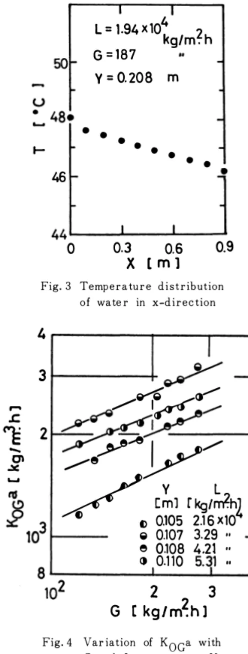
Typical examples of the temperature distribu
tions of water in the x and y-direction in the bubble-water contact section ( test section) are shown in Fig. 2 and 3 res pectively. The varia
tions of the water temperature in the y-direc
tion are small as shown in Fig. 2. This means that the present enthalpy transfer proces s 1s similar to the case of single pas ses, one fluid mixed and other one unmixed
ma cro s s flow heat exchanger. Accordingly, the correction factor F in Eq. (lO) are taken from the graph for that case. As seen in Fig. 3, the water tem
perature decreases almo st linearly with the dis tance from the inlet, supporting the as sumption
-48 -
measured values into the followig
E
>
(10)
0.2
0.15
0.1 �
X [m)
]
e 0.0E e 0 .3
i
0 0.6�
i � • 0.90.05
0 46
F ig . 2 Te mp e r atu re d i s tr ibution o f wat e r in y -d i r e c tion
Exp e r i me n tal Inve s tigation on Bubble Coo ling f o r Large Amount of He a t e d Wa s te Wate r H i s a s h i MIYA S HITA, S h ink i c h i YAMAGUCHI and Kazu h iko KITA
of uniform contact of water and gas bubbles.
The correlation of Koca were made by chang
ing water flow rate L and air bubble flow rate G at the constant depth of water flow. Figure 4 presents the experimental results which indicate that Koca increases with increasing flow rates of both water and gas. From this figure, K0ca is found to vary proportionally to c0 . 54
In order to examine the effect of the depth of flowing water, Koca was determined in the range Y between 0 . 084 and 0 . 156m, and the result is shown in Fig. 5 . The fact that Koca is inde
pendent on Y, as shown in Fig.6, indicates that the end effect for non-uniform contact of the air bubbles and the water in the region close to the
l = 1.94X10⁴ 2
kg/m.
h50 G
=187Y
= 0.208m
• • •
1- • • •
• •
46
•44�--_.----�--�
0 0.3 0.6
X [ m 1
0.9Fig. 3 Temp e r a tu r e d i s t r ibution o f wate r in x-d i r e c tion
air nozzles is negligibly small in this experi- 4
I
mental apparatus.
Ten perforated tubes are placed at intervals of 0 . 1m on the bottom of the stream channel, that is, x is 0 . 9m. In order to examine the effect of x on Koca, X was varied by removing the tubes from both ends in the test section. The experiments were carried out for four values of
x,
0 . 9, 0 . 7, 0 . 5, 0 . 3m retaining a constant flow rate L, and a constant water depth Y. The result is shown in Fig. 6. It is seen in Fig.6 that the values of Koca do not depend on the number of the perforated tubes; They are independ of the length X of the cotact section. This result
2
I I/
L
=2.18 X10⁴ �ofii
r-
[k � y[m)
t o0.085
£. �0.095
-. I e0.126
()() 0.152 o.105
-[ kg I m� h 2 I
Fig. 5 Effe c t of d e p th of wate r flow on Koca
3
3 � -
... ��<r'
,...
ce 2
.c. -� YAI r
/.X 0\
...
�y _...--e
() () 0.105 2.16X10v Cml r kgtrlth L 2
�
0.107 3.29 ..e 0.108 4.21 ..
() 0.110 5.
i
1 ..2 3
G r kg/m�h 1
Fig. 4 Var iation of Koca w ith G and L at c o n s tant Y
2 4
G [kg/m�hl 6
Fig. 6 E ffe c t of length o f c ontact s e c tion on Koca
Bulletin of Faculty o f Engine e r ing Toyama Un ive r s i ty 1982
IS
an indirect evidence of uniform distri- bution of air bubbles.
Since Koca is found to be a function of flow rates of water and bubbles as shown in Figs. 4 to 6, values of Koca/
0.54 are plotted against L in Fig. 7 . Though the data are somewhat scatterd, Koca is approximately proportional to L0.5; the following equation is obtained:
Koca
=o.67 (L)0·5 ( G )0·54 (11) Equation (11) is valid under the following experimental conditions,
1.3
X104 < L <9.5
X104 1
01
X102 < G < 6
00
X102
0.084 <
y< 0.156 0.3 < X < 0.9
40 < T <50
Discussion
m m 'C
/;11
f-1-
I
104 2
L
Afl>re
!lf('§J
1�/
,_�_....¥
4 6 8 105 kg/ m�h l
-
F ig. 7 Co r r elation o f
Koca/G0.54
w ith LThe overall enthalpy transfer resistance 1/Koc is expressed as the sum of res is tances
mwater and in air respectively:
1
Koc (12)
where m is the slope of the equilibrium curve of saturated enthalpy versus temperature, the heat capacity of air in the bubble, hL and he the water and air side heat transfer coefficients respectively. In deriving eq. (12), the Lewis relation is used.
Very few data have been published for the studied cooling device; this cross flow
condition might be similar to that of the flows on trays in bubble-cap or sieve-plate
3, (8)
columns; for these, some mass transfer have been presented in terms of plate efficiency.
Unfortunately, it is difficult to compare our heat transfer data with these mass transfer data because the empirical results for mass transfer do not account for several signifi
cant variables, including fluid velocities, tray dimensions, and some physical properties.
Gerster et a!. obtained the empirical equation for gas- and liquid-phase mass trans-
4)fer resistances for several tray designs. Assuming the analogy between heat and mass
·transfer, one can calculate the values of m/hLa and CH/hca from their empirical relations. The calculated result for L=4x10⁴ and G=200 kg/m2.h shows that the gas phase resistance predominates and the calculated value of the overall coefficient Koca is about 25% higher than that obtained in the present experiment. However, the dependen
cy of the calculated K0ca on L and G does not agree with the present result. There
fore, it is neccesary to execute more detailed exqeriments in order to obtain better
-50-
Exp e r i me n t al Inv e s tigation on Bubble Cooling fo r La rge Amount of He ated Wa s t e Wa t e r H i s a s h i MIYAS HIT A, S h in k i c h i YAM AGUCHI and Kazuh iko K IT A
10 E
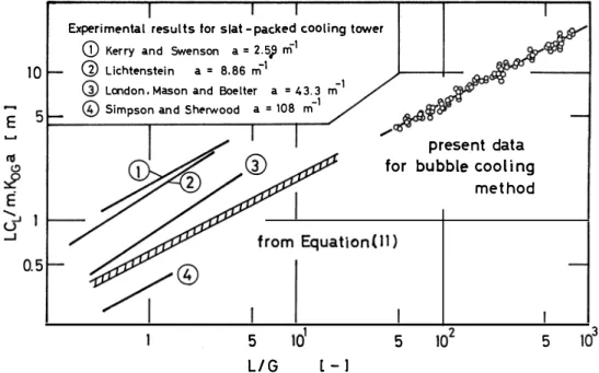
Experimental results .tor slat -packed cooling tower
(j)
Kerry and Swenson a=2.5j m1 G)
Lichtenstein a = 8.86 m-1r.:-. -1
I..:V LCX'Idon. Mason and Boelter a = 43.3 m
f7\
-1
\!!./ Simpson and Sherwood a = 108 m
5
LIG l-1
present data for bubble cooling
method
5
Fig. 8 C o mpa r i s o n with exp e r ime ntal valu e s o f he ight of t r a n s fe r u n i t fo r slat-packed c ooling towe r s
5
understanding the transfer mechanism between bubble and water flows in such a cooling system. Though the present experimental conditions differ from those in cooling towers, the results are compared in Fig. 8 with the experimental values for slat-packed
5, 6, 7,10)
cooling towers from various sources. All of the present data exist in the region of ve ry large values of L/G. If we assume that the present results can be extended to the region of small values of L/G, the value of Koca for the bubble cooling is somewhat larger than those of kerry et al., Lichtenstein and London et al., and smaller than that of Simpson et al. That is, the present cooling method can be used for the cooling of a large quantities of water with somewhat better performance than that obtained with cooling towers.
Conclusion
To cool a large amount of discharged waste water, bubble cooling method was studies.
The overall enthalpy transfer coefficient Koca obtained by the experiments is inde- pendent of depth of water and. length of the contact section. The dependence on L and G can be represented by the empirical equation:
Koca = 0.67 ( L)0.54( c ) 0.5
in the ranges 1.3x10⁴
<L
<9.5xl04 kg/m2.h, 110
<G
<600kg/m2.h, 0.084
<Y
<0.156 m, 0. 3
<X
<0. 9m, 45
<T
<50"C
It was observed that this cooling system could be effectively used for cooling of a
large amount of waste water with somewhat better performance than that involving a
cooling tower.
Bu l l e tin of Fac u l ty o f Engin e e r ing Toyama Un ive r s ity 1 982
Acknowledgment
The financial support of the Ministry of Education, Science and Calture through a Grant-in-Aid for Special project pesearch (No.210414) is greatfully acknowledged.
Literature Cited
1 ) Bowman R. A., A. C. Mueller and W. M. Nagle: Trans. AS ME, 62, 284 ( 1940) 2 ) Bregman .J. I. : Chern. Engr., 25, 83, Jun. (1971)
3 ) Dickamer H. G. and J . R. Bradford: Trans. AIChE, 39, 319 (1943)
4 ) Gerster J. A., A. B. Hill, N. N. Hochgraf and D. G. Robinson: "Efficiencies
mDistilla- tion Columns, final report" Research Committee, AIChE, New York (1958)
5 ) Kerry N. W. and L. K. Swenson: Chern. Eng. Progr., 52, 263 (1956) 6 ) Lichtenstein J. : Trans. ASME, 65, 779 (1943)
7 ) London A. M.,
W.E. Mason and L. M. K. Soelter: Trans. A S ME, 62, 41 (1940) 8 )
0'Connell H. E. : Trans. AIChE, 42, 741 (1946)
9 ) Porter R. W. and K. H. Chen: Trans. A S ME, 96, 286 (1974) 10) Simpson W. M. and T. K. Sherwood: Refrig. Eng., 52, 535 (1946)
Nomenclature
a effective interfacial area (m2 fm3J CL heat capacity of water (J/kg. KJ F correction factor (- J
G mass velocity of bubbles based on channel surface area (kg/m2.hJ enthalpy of air (J /kg-dry air]
iL saturated enthalpy of air at water (J/kg-dry air J temperature T (J/kg-dry air J
KoGa = overall coefficient of enthalpy transfer (kg/m3.h]
L mass velocity of heated waste water based on cross sectional area of the ch- annel (kg/m2.hJ
m slope of saturated enthalpy-temperature curve (J/kg. KJ P function of correction factor (-J
R function of correction factor (-J T temperature of the water ('CJ
temperature of the air ('CJ X length of the contact section (mJ
v longitudinal coordinate (mJ Y depth of the water flow (mJ y vertical coordinate (mJ
Z
width of channel (mJ z = transverse coordinate (mJ
Subscripts
1 inlet 2 : outlet
- 52 -