N-Phase Synchronization Observed in a Ring of Large-Scale Coupled Circuits
Takuya Nishimoto
∗, Yoko Uwate
∗, Yasuteru Hosokawa
†, Yoshifumi Nishio
∗and Dani´ele Fournier-Prunaret
‡∗Dept. of Electrical and Electronic Eng., Tokushima University, 2-1 Minami-Josanjima, Tokushima, 770-8506 Japan Email:{nishimoto, uwate, nishio}@ee.tokushima-u.ac.jp
†Dept. of Media and Information Systems, Shikoku University, Furukawa, Ohjin, Tokushima, 771-1192, Japan
Email: [email protected]
‡LAAS-CNRS, 7 avenue du colonel Roche, F-31077 Toulouse Cedex 4, France Email: [email protected]
Abstract—Chaos synchronization can be observed in various natural systems. In this study, we investigated synchronization phenomena on a ring of coupled chaotic circuits. We can observe N-phase chaos synchronization and simple synchronization phe- nomena depending on initial values in the system. This paper suggests ring topology and alternately shifted bias are essential factor of N-phase synchronization.
I. INTRODUCTION
Chaos synchronization observed on large-scale coupled chaotic systems have been attracted attentions in various science field because it can be regarded as models of real physical system. For instance, chaos phenomena have been reported in engineering, biology, economics, astronomy and so on. Therefore investigation of synchronization phenomena on high-order chaotic systems are very important to grasp essentials of the phenomena observed in natural system.
On the other hand, some chaotic circuit have coexist- ing attractors[1]. Asymmetric attractor observed in the sys- tem which is symmetric structure causes some interesting phenomena[2][3]. However there are not many studies of synchronization on asymmetric attractor. It is considered that observation of synchronization phenomena in the state of chaos on asymmetric attractor is difficult.
In this study, we also investigate synchronization phenom- ena in a ring of coupled chaotic system whose subcircuits gen- erate asymmetric attractor. 2-types synchronization phenomena depending on initial values can be stably observed in the system. Especially, N-phase chaos synchronization observed in the system(N = 6∼50) is extremely interesting phenomena since N-phase synchronization can be observed in small-scale coupled chaotic system normally. In this study, we confirmed N-phase synchronization phenomena on large-scale system.
By carrying out circuit computer simulations, we can confirm the phenomena above. This paper is organized as follows. In Section II, we propose the a ring of coupled chaotic system.
Section III, 2-type chaos synchronization are shown. Finally, Section IV concludes this paper.
II. SYSTEM MODEL
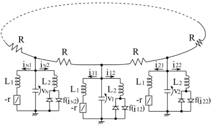
The system model is shown in Fig.1. Each subcircuit is coupled by resister. Subcircuit is chaotic circuit which consists
i22
i21
v2
f( )i22
L1 L2
iN2
iN1
vN
f( )iN2
L1 L2
-r
i12
i11
v1
f( )i12
L1 L2
-r -r
R R
R
R
Fig. 1. System model.
three memory elements, one linear negative resister, and bi- directionally-coupled diodes proposed by Nishio et al[5]. First, we approximatei−vcharacteristic of bi-directionally-coupled diodes as following function:
f(in2) = 1
2(|rdin2+V| − |rdin2−V|) (1) where parameterrddenotes slope of nonlinear resistance. Then the system equation is described by the following 3×N- dimensional ordinary differential equation:
L1din1
dt = vn+rin1, L2
din2
dt = vn−f(in2), Cdvn
dt = −in1−in2+ 1
R(vn−1−2vn+vn+1). (2) By changing the parameters and variables,
t=√
L1Cτ, in1=V
√C L1
xn, in2=V
√C L1
yn, vn=V zn,”·” = d
dτ, α=r
√C
L1, β= L1
L2 γ=rd
√C
L1 and δ= 1 R
√L1
C
(3)
- 1 -
IEEE Workshop on Nonlinear Circuit Networks December 13-14, 2013
the normalized system equation is described as follows:
˙
xn = αxn+zn,
˙
yn = β {
zn−fˆ(yn) }
,
˙
zn = −xn−yn
+δ(zn−1−2zn+zn+1), (n= 1,2,· · ·, N)
(4)
where
z0=zN, zN+1=z1 and
fˆ(yn) = 12(|γyn+ 1| − |γyn−1|).
Figure 2 shows an example of asymmetric chaos attractor depending on initial value obtained from one subcircuit. For the computer simulation, we fixed the parameters as β = 3.0 and γ= 470.0. Asymmetric attractors are distinguished with 2 colors in simulation result. In this study, we distinguish the attractors as following definition:
(1) A Poincar´e section is defined at zn = 1.0 and
˙ yn<0.
(2) When the solution hits the Poincar´e section, and yn>0.675, the color is set as red and such state is defined state{M}. In the case of yn ≤0.675, the color is set as blue and defined state{P}. This definition is important to grasp the domain of attractor in each subcircuit and as such, is being applied to following simulation results in this paper.
III. 2-TYPE CHAOS SYNCHRONIZATION
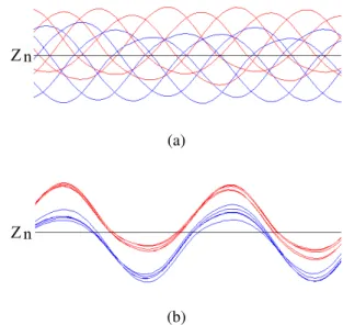
2-type synchronization phenomena depending on initial values can be observed in the system shown in Fig. 1. Figure 3 shows the examples of synchronization phenomena. N-phase chaos synchronization is shown in Fig. 3 (a), and synchro- nization in Fig. 3 (b). Red and blue colors show the state
(a)α= 0.35
(b) r= 4.99
Fig. 2. Asymmetric chaos attractor observed in a subcircuit. (a) Simulation result. Horizontal:y1. Vertical:z1.β= 3.0andγ= 470.0. (b) Circuit exper- iment. Horizontal:i12[0.1mA/div]. Vertical:v1[V/div].L1= 642.8[mH], L2= 211.1[mH]C= 7.06[nF].
Zn
(a)
Zn
(b)
Fig. 3. 2-type synchronization phenomena depending on initial values. (a) N-phase chaos synchronization. (b) Synchronization. Vertical:zn. Horizontal:
τ.N= 10,α= 0.425,β= 3.0,γ= 470.0andδ= 0.20.
M
P
M
P
P or M
Fig. 4. Overview of attractor domain.
{M} and {P} respectively. Both synchronization states are not synchronized rigorously since the system generates chaotic signal. However, those behavior shown in Fig. 3 (a) and (b) are almost synchronized. Therefore these phenomena are called N-phase synchronization and synchronization respectively in this paper. It should be noted that when the subcircuits (n is odd number) take state {P}, while the others (n is even number) take state{M}in Fig. 3. Namely, the subcircuits take opposite attractor state with respect to the neighbor subcircuits.
An overview of attractor domain is shown Fig. 4. This is the one of the characteristic of this chaotic circuit in case of coupled by resister. It is considered that shifted bias waveform be caused due to the characteristic in this system. Figure 5 is simulation results in state of N-phase chaos synchronization.
The phase difference betweenz1andznare gradually enlarged from z1 vs z2 to z1 vs z6. Moreover, z6, which are located diagonal position of z1, is almost synchronized with anti- phase. Figure 6 shows time waveforms and lissajous figure of z1 and z6 observed in simulation. While z1 takes state {P},z6 takes state {M} and almost synchronized with anti-
- 2 -
(a)z1 vs z2 (b)z1 vs z3 (c)z1 vs z4
(d) z1 vsz5 (e)z1 vsz6 (f)z1 vs z7
(g) z1 vsz8 (h)z1 vs z9 (i)z1 vsz10 Fig. 5. Lissajous figures in state of N-phase chaos synchronization (Computer simulations).z1vszn.α= 0.425,β= 3.0,γ= 470.0andδ= 0.2.
(a)
Z1
Z6
(b)
Z1
Z6
(1) (2)
Fig. 6. Almost anti-phase synchronization state forN = 10. (a) N-phase synchronization. (b) In-phase synchronization. (1) Time waveforms ofz1and z6. (2)z1vsz6. (parameter values are the same as those in Fig. 5).
phase as shown in Fig. 6 (a). Figure 6 (b) shows another type synchronization. Although z1 and z6 take opposite attractor state, these circuits are almost synchronized with in-phase.
These behavior shown in Fig. 6 (a) and Fig. 6 (b) can be observed by giving different initial values.
From these results, we can confirm that subcircuits located in diagonal position are synchronized with anti-phase or in- phase though both subcircuits take opposite attractor state.
Moreover, 2-type synchronization phenomena can be observed in large-scale case around N= 50.
IV. CONCLUSION
In this study, we have investigated synchronization phe- nomena on coupled nonlinear circuit as a ring. As a result, N- phase synchronization and simple synchronization phenomena are observed in a ring of large-scale coupled circuits. It is considered that essential factors of 2-type synchronization depending on initial values are ring topology and alternately shifted bias. This result is extremely interesting and would give the effective suggestion to make clear the nonlinear phenomena in large-scale high dimensional system. In our future work, we investigate the mechanism of N-phase synchronization phenomena on another circuit system.
REFERENCES
[1] L.O. Chua, M. Komuro and T. Matsumoto, “The doulbe scroll family”, IEEE Transactions on Circuit and Systems, vol. 33, no. 11, pp. 1073- 1118, Oct. 1986.
[2] H. Sekiya, S. Mori and I. Sasase, “Synchronization of Self-Switching phenomena on Full-Coupled Chaotic Oscillators”, IEICE Trans., vol.J83- A, no. 11 pp. 1264-1275, 2000.
[3] T. Nishimoto, Y. Hosokawa and Y. Nishio, “Anti-Phase Synchronization of Switching Phenomena in Globally Coupled System of Chaotic Cir- cuits”, IEICE Technical Report, no. NLP-48 & CAS2010-32, pp. 1-4, 2010.
[4] Y. Nishio, K. Suzuki, S. Mori and A. Ushida, “Synchronization in Mu- tually Coupled Chaotic Circuits”, Proceedings of European Conference on Circuit Theory and Design(ECCTD’93), vol. 1, pp. 637-642, Aug.
1993.
[5] Y. Nishio, N. Inaba, S. Mori and T. Saito, “Rigorous Analyses of Windows in a Symmetric Circuit”, IEEE Transactions on Circuit and Systems, vol. 37, no. 4, pp. 473-487, Apr. 1990.